To diagnose a VAZ 2114, 2113 or update the ECU firmware, car owners, diagnosticians or mechanics need to know the location of the OBD2 diagnostic connector, as well as its pinout and type. To flash the electronic unit or replace it, you also need to know the location of the ECU and the purpose of the pins.
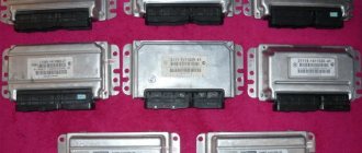
For a VAZ 2114 car, the type of block depends on the year of manufacture and the type of ECU:
Where is the diagnostic connector for the VAZ-2114
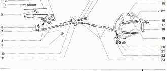
VAZ 2108-2115 with a “European panel”, the diagnostic connector is located in front of the gearbox, directly under the cigarette lighter. The block is closed with a decorative cover. On injection models since 2002, a 12-pin rectangular connector has been used.
The location of the connector is indicated on the diagram in position No. 8 . The following are visual photos of the diagnostic block.
Photo of the block location:
About the ECU and its location is written in the article “Diagnostics of VAZ 2114”. The following shows the pinout of the OBD2 connector and the assignment of contacts of the electronic control units that were installed on the Fourteenth VAZ models.
Connector type No. 1—16-pin OBD-II connector in the shape of a trapezoid:
Brands and years: some models after 2002 with control systems BOSCH MP7.0 Euro-3, BOSCH M7.9.7, January-7.2, January-7.3.
Connector type No. 2 - 12-pin rectangular connector: Make and year: all injection models, except for some models after 2002 that have an OBD-II connector
Video “Why the ECM does not communicate during testing”
From the video below, you can find out why there may be no communication between the ECM and the laptop during diagnostics (the author of the video is the Billye espada channel).
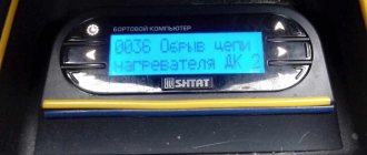
Please tell me. The on-board computer says “no connection with the maintenance controller.” What to do in this situation?
- Will BOSCH 0-280-150-996 injectors fit the January 7.2 ECU? – 2 answers
- Why does the on-board computer constantly reboot when starting the engine? – 2 answers
- Interruptions in the operation of the VAZ 2114 engine - 2 answers
- Should I flash the VAZ Samara controller? – 2 answers
- How to replace the Bosch ECU for January 2115? – 1 answer
Does the on-board computer have any connection with the controller?
If the engine starts and runs without problems, then you need to deal with the B/C, there is often a break in the K-line (the wire to the OBD-2 comes off), one might say - one of the main wires.
Terminal No. 7 of the diagnostic connector.
Probably the wire of the hog computer jumped out of it.
Even more useful tips in a convenient format
Interruptions in the operation of the VAZ 2114 engine
Why does the on-board computer constantly reboot when starting the engine?
OBD1 pinout - 12 PIN (GM12)
Description:
OBD1 (GM12) connector is rectangular in shape, consists of 12 contacts.
Brands and years:
All injection models, except for some models after 2002, which have an OBD-II connector.
Access and location:
Open access. Located next to the ignition switch, partially covered by the steering column cover.
Pinout:
| M | L | K | J | H | G |
| A | B | C | D | E | F |
| Key * | |||||
* Connector Keying - A design element of a removable connector that ensures the correct orientation of the plug and socket.
Example in the photo:
Conclusions and their purpose:
| Conclusion | Color | Purpose |
| A | Weight | |
| B | L-line diagnostics (not always routed) | |
| D | CO potentiometer (not always diluted) | |
| G | Fuel pump control | |
| H | Power supply +12V (not always wired) | |
| M | K-line diagnostics |
OBD2 pinout - 16 PIN
Description:
The OBD2 connector is trapezoidal and consists of 16 pins.
Brands and years:
Gasoline passenger cars and light commercial vehicles manufactured or imported into the United States since 1996 (US CARB and EPA legislation) and in Europe (EOBD) since 2000-2001 (European Union Directive 98/69EG) and Asia (mainly since 1998). ).
Access and location:
Pinout:
| 1 | 2 | 3 | 4 | 5 | 6 | 7 | 8 |
| 9 | 10 | 11 | 12 | 13 | 14 | 15 | 16 |
| Smaller side of trapezoid | |||||||
Example in the photo:
Conclusions and their purpose:
| № | Color | Purpose |
| 2 | J1850 Bus + | |
| 4 | Body grounding | |
| 5 | Signal Ground | |
| 6 | Line CAN-High, J-2284 | |
| 7 | K-line diagnostics (ISO 9141-2 and ISO/DIS 14230-4) | |
| 10 | J1850 Bus- | |
| 14 | Line CAN-Low, J-2284 | |
| 15 | L-line diagnostics (ISO 9141-2 and ISO/DIS 14230-4) | |
| 16 | Power supply +12V from battery |
Diagnostic connector pins for used protocols
Pins 4, 5, 7, 15, 16 - ISO 9141-2.
Pins 2, 4, 5, 10, 16 - J1850 PWM.
Pins 2, 4, 5, 16 (without 10) - J1850 VPW.
The ISO 9141-2 protocol is identified by the presence of pin 7 and the absence of pins 2 and/or 10 on the diagnostic connector.
Features of checking wires included in various devices
The specificity of this situation is that the wiring in the case under consideration consists of one linear conductor with a supply voltage of 12 Volts. In this case, the metal body of the car is used as the second (common or “ground”) conductor, where, as a rule, there is nothing to break.
To prepare the on-board network for inspection, you first need to disconnect the positive terminal from the battery, after which you can safely begin work. Testing of on-board wiring is organized according to the previously described linear circuit testing scheme.
When checking the “ground” of a car, the main attention is paid to the quality of contact of the supply terminals with the body
Electric heating element
Based on the indicator readings on the multimeter, it is possible to make a continuity test on an element such as a water heating element. During the test, the control probes of the device touch the two contact plates of the heater and evaluate its internal resistance using the indicator.
In addition to the heating element itself, when checking boilers and similar devices, it is very important to ring the supply cable for unwanted contact with the device body. For this purpose, one of the multimeter probes is connected in turn to the input contacts; while the second end is constantly held on the heater body
If the digital multimeter shows some resistance during measurement, this means that the protective sheath of the supply cable is damaged. To prevent electric shock to the user, it should be replaced with a new one.
Using a multimeter, you can test the power circuit of any lighting device by testing the wiring and auxiliary elements (switches, in particular) for a short circuit or open circuit. To do this, first of all, you should ring two linear chains ending directly at the contacts of the light bulb.
When testing linear chains, be sure to check the serviceability of the switch located in one of them, as well as the reliability of connecting the conductors to its contacts.
We also note that using this method it will be possible to ring the windings of a linear transformer or electric motor and verify their integrity or the presence of a break (short circuit).
Pinout and where is the diagnostic connector for VAZ-2112
Diagnostics of modern car models is carried out using a special diagnostic connector. It connects to a computer, which analyzes the current state of the vehicle, determines the malfunction and indicates it. If you have the appropriate equipment, you can look for breakdowns even at home. However, not all VAZ-2112 owners can find the diagnostic connector right away. Today we’ll talk about its location on the classic panel and on the Europanel. In which part of the car should I look for the required socket?
Why do you need an on-board computer?
In previous articles we have already talked about what an on-board computer is, what it is needed for and what types they come in. But let me repeat myself so that you clearly understand all the advantages of having an on-board computer, and there are probably no disadvantages, except perhaps spending money on the purchase and that’s all.
Let's take, for example, the on-board computer STATE 115×24. With this model in your possession, you can:
- set the radiator fan start temperature; this function is very useful, for example, in winter, when you can control the temperature of the coolant, thereby monitoring the temperature of the heater radiator.
- The function of drying and warming up the spark plugs before starting the engine is very useful.
- The function of resetting settings and ECU adjustments is needed to switch to gasoline with a higher or lower octane number (from 92 to 95 and vice versa), and this function is also needed to reset settings after a long trip with increased load on the engine.
- The ability to read errors allows you to monitor the condition of the car and change non-working sensors and elements in a timely manner.
Where to look for the connector
It is important to know that on different cars the required socket is located in different parts of the car. Moreover, on some AvtoVAZ models it may be in a completely different place compared to another car. Let's look at several VAZ cars as an example:
- on the VAZ-2112, as well as on the 2110, as well as 2111, the socket is located to the right of the driver’s seat, immediately under the column;
- on models 2108, 2109 and 21099, the socket you need is located under the glove compartment, on a special shelf;
- on cars with a europanel it can be found in the center of the console, near the cigarette lighter. A special decorative cover is used to disguise it;
- on Lada Kalina cars, the connector can be found near the gear shift lever. As is the case with cars with a Europanel, it is hidden under a special cover;
- on a Priora you need to look for it right behind the glove compartment, on the wall.
Thus, on the VAZ-2112 the diagnostic connector is located on the right side of the driver’s seat. It is located immediately under the steering column and, in principle, is not so difficult to find. Inspect the bottom of the panel.
Example of wire continuity
Continuity of wires in buzzer mode
Situation: the socket in one room does not work. The user's task will be to find the cause of the failure. To solve it you will need:
- See if the automation in the shield worked. If the elements are turned on, de-energize the specific line or apartment completely.
- Remove the socket from the socket box and perform a visual inspection for external defects and quality of contacts.
- On modern models, the terminal blocks ring.
- If the socket is not damaged, test the quality of the connection of the conductors in the junction box next to the socket.
- The main cable in the distribution box must be broken, connected to the conductors under the socket and routed to the next consumer.
- There are 3 twists in the distribution box - neutral, ground and phase. Use the tip of the probe to touch the exposed twist.
- The second tip rings the socket contacts in turn. You can fix one probe on the contact, and check the twist with the second.
There are no terminal blocks for standard sockets.
Wire testing process
The measurements have several nuances:
- If the twist is without defects, it makes sense to test the live wiring. It is necessary to supply current by turning on the switchboards.
- If you are in doubt about the color marking, the phase is determined by touching the indicator screwdriver - the diode should light up.
- Working and protective grounding are checked in ACV mode greater than 220 V. The red probe is in phase, the black one is used to find zero and ground. The working grounding N is reflected in the range of 220 A, the protective grounding PE is less than 220 V.
- It is taken into account that electricians do not always route wires into the junction box. The outlet can be powered from the adjacent one or the elements of the adjacent room can be placed at common points on the walls.
- Due to the length of the probes 30-50 m, it is allowed to connect the socket contacts with a jumper and a continuity tester in the junction box.
Pinout
Knowledge of pinouts may be required if a car enthusiast wants to make an adapter for computer diagnostics with his own hands, or if you need to connect without one. Experts recommend buying ready-made devices without the need to make a plug yourself. However, if you do not have such an opportunity, and diagnostics need to be carried out urgently, we will consider two main pinout options used on VAZ cars of various years of manufacture. Until 2002, AvtoVAZ products used the following pinout option:
- The 4th and 5th pins are GND outputs.
- Pin 16 – +12 V (power line).
- The 7th contact is the diagnostic line itself.
Since 2002, the pinout scheme has changed significantly. Now it looks like this:
- Pin H – +12 V (power line).
- Contact G – +12 V for the fuel pump.
- Pin A – GND output.
- Contact M – diagnostic line.
Checking the connector contacts
We have already carried out a preliminary check and made sure that power is supplied to the ignition module. Now it’s worth dealing with the contacts separately. With the ignition on, you need to connect a test lamp to contact A and contact B.
The control can be a regular low-power 12-volt lamp with soldered wires, or you can use a car test probe with a 12-volt voltage indicator.
Checking the ignition module
To check the functionality of the module, we attach the contacts from the test lamp or probe to terminals A and B, then crank the engine with the starter.
In this case, everything is in order with contacts A and B.
Pinout of diagnostic connectors for VAZ and GAZ cars
Currently, the vast majority of cars have an OBD2 diagnostic connector (trapezoidal 16-pin block, usually located in the steering wheel area). Through this connector you can connect diagnostic equipment to diagnose your car, as well as connect on-board computers and other devices that work through the diagnostic connector.
People often have questions about the pinout of diagnostic blocks for some cars. Our store has various adapters for different models. But if you forgot to order an adapter for your car, you can try to make it yourself, or connect the adapter directly. To do this, we have prepared for you a short review on the pinout of the OBD2 socket, the pinout of the sockets for VAZ and GAZ cars.
OBD2 connector pinout
This option has been common in foreign cars since 2002, and is also installed in all VAZ cars after 2004.
Pin designations: 7 - K-diagnostic line 4/5 - GND protruding contacts 16 - +12V adapter power supply
Pinout of the VAZ block before 2002:
Contact designations: M - k-diagnostic line H or G - adapter power supply +12V
When connecting an adapter without a block directly to the wires, it is better to take power from the cigarette lighter, since the contact shown in Figure H, depending on the model, may not be routed, and when using the G contact, the fuel pump gives very large impulses that can damage the adapter.
Pinout of GAZ/UAZ block:
Contact designations: 2 - Power supply of the adapter +12V 12 - ground 10 - L-diagnostic line (may not be wired, as a rule not used) 11 - K-diagnostic line
If you are interested in pinouts of connectors of other brands, you can refer to the specialized reference book.
Did you like the article? Save it for yourself!
Lada 2110 Green Arrow › Logbook › Do-it-yourself diagnostics using the K-line, part 1
Aleksandr Matskovich, 29 years old I drive Lada 2110 Green Arrow Kryvyi Rih, Ukraine
Good day to everyone who is reading this entry! And so I’ll start with the fact that I don’t have an on-board computer, I have a desire to install it, but more on that later. There was an interest in identifying my car with my own hands. In one of the previous articles, I wrote that after a rainstorm I filled up the air flow sensor, the check light came on and I went for diagnostics: they charged me 100 UAH. Within 30 seconds, having discovered that the sensor does not work, it needs to be replaced. I don’t need professional diagnostics; if necessary, I’ll go to a diagnostician, and for easy diagnostics, I decided to buy a K-line scanner
VAG-Com 409.1 K – Line scanner
oh, and even though my car is from 2004, it is 1.5l and 8kl with EURO-2, and is equipped with an ODB-1 connector. I googled it: it turns out that ODB-2 was already installed but on 16kL cars with EURO-3 from earlier years. I also had to buy an adapter with
Adapter OBD-II 16pin to GM12
I ordered everything from the online store, along with the cords I received a disk with programs for diagnostics and a bunch of different information on diagnostics. I configured all the com ports on the laptop and went into the garage with the laptop to try. I plugged it in, turned on the ignition, bam, and the fuel pump immediately began to hum without stopping. Naturally, nothing happened and I abandoned the matter (and this was last year at the end of autumn). Well, it’s already warm - there is a desire to resume this business. When I rang the adapter, I didn’t really understand anything, one rings 3 at a time, some don’t ring at all, I decided to redo it all. As you know, for diagnostics via the K-line you only need 3 wires (channels): 1) potassium itself 2) +12V 3) -12V aka ground, ground
The first message on the screen of diagnostic equipment or a computer that causes panic among beginners is usually something like “No connection”, “No controller response” or something similar, but no less intriguing. The motor tester, for example, begins to offer options - from unconnected power to a hardware malfunction of the adapter. It’s good if the car with the immobilizer was the first to arrive for diagnostics and you are sure that everything is in order with the adapter. The reason for the lack of communication on cars without immo is trivial and is possible only in the domestic auto industry - a break in the diagnostic line running from the diagnostic connector to the ECU. The immobilizer uses K-Line to communicate with the ECU and is included in the diagnostic line break. If the immobilizer is not installed, then the diagnostic line hangs in the air and there is no connection with the computer. Apparently there was supposed to be a plug in this place, but... To restore communication, you simply need to install a jumper between pins 9-1 and 18 of the immobilizer connector (or install an immobilizer) as shown in the figure. In practice, to preserve the functions of smooth dimming of light, and simply to scare away pioneers, these two wires are cut and spliced, leaving the immo in the connector.
GAS diagnostic connector.
1 +12V 2 +12V from battery 10 L-Line 11 K-Line 12 Ground
Diagnostic connector VAZ
A - GND B - L-Line (may not be) M - K-Line G - Fuel pump control.
H - 12V. Constant from the battery through a fuse. /may not be.
WHAT TO DO WHEN A BC STOPS WORKING
This sometimes happens when the on-board computer does not work. What do experts advise to do in this case? The first step is to determine the type of malfunction of the device. If it does not show “signs of life” at all, you need to check fuse F3, which is installed in the power supply circuit of the VAZ 2114 processor. If replacing it does not “revive” its operation, check the connection connectors.
There is no point in describing the essence of the process of repairing such a complex electronic product, since for this, in addition to having the necessary devices and tools, you also need to have an education in the field of electronics.
Where is the diagnostic connector located?
On different cars of the VAZ family, the socket is located in different parts of the car. Let's look at a few models as an example:
- on the VAZ-2112 , as on the 2110 , as well as the 2111 , the socket is located to the right of the driver’s seat, immediately under the column;
- on models 2108 , 2109 and 21099 , the socket you need is located under the glove compartment, on a special shelf;
- on cars with a europanel it can be found in the center of the console, near the cigarette lighter. A special decorative cover is used to disguise it;
- Lada Kalina cars the connector is near the gear shift lever, it is also hidden under a special cover;
- On a Lada Priora, look right behind the glove compartment, on the wall.
VAZ 2110
How to diagnose a car
- Connect contact “B”, which has the diagnostic block and “ground”;
- Turn the ignition key to the third position, do not start the car;
- First, the “CHECK ENGINE” lamp displays code 12 with 3 flashes. It shows that the diagnostic programs are working. On the VAZ 2110 this happens in this order: the lamp blinks briefly 1 time (which should be considered the designation of number 1). After a pause lasting at least 2 seconds, it flashes 2 times in a row (two). So we got the number two. And this is repeated 3 times so that the driver understands these signs;
- After the diagnostic program has declared its serviceability, it will begin to display error codes, if there are any, of course. In the same way - flashes and pauses.
Program interface
If we talk about ELM 327 interface OBD 2, then it is intuitive. After establishing the connection, you must wait until the flashing car icon stops blinking. If everything was correct, then the device will immediately start working.
Let's figure out how to use the auto scanner, or rather, which of the Torque program icons will interest us most:
- OBD Check Fault Code – allows you to read and decipher possible vehicle errors.
- Realtime Information – counters that display engine parameters in real time. The user can independently select and add the counters he needs. To do this, click “Add Screen”.
- Map View – displays the route of movement.
While the car is moving, the driver can monitor the indicators of pressure sensors, speed, fuel consumption and much more.
If you want to receive more detailed data about car systems, it is recommended to connect to the ELM scanner via a PC.
Deciphering error codes
The first character is a letter and indicates a fault block:
- B - body;
- C - suspension;
- P — engine (ECM, gearbox);
- U - data exchange bus.
The second character is a number, code type:
- 0 — SAE (standard);
- 1.2 - OEM (factory);
- 3 - reserved.
The third character is a number, system:
- 1, 2 - fuel system;
- 3 - ignition system;
- 4 — reduction of exhaust gas toxicity;
- 5 - idle;
- 6 - ECU or its circuits;
- 7, 8 — transmission (automatic transmission).
The fourth and fifth characters are numbers, the error code itself.
Features of using the USB K-Line adapter:
- operates in a wide range of device supply voltages from 8.0 to 18 V;
- recommended temperature for use of the device is from -40 to 40 ° C;
- providing communication with a direct one-wire interface directly to a standard connector;
- connecting diagnostic testers;
- simple communication with the vehicle's ECU;
- protection against short circuit to ground;
- low current consumption during operation.
Although the K-Line diagnostic protocol is still widely used today, it no longer plays a significant role in new developments of automotive systems for solving diagnostic tasks performed via K-Line. However, car manufacturers around the world have not ruled out the fact that many vehicle ECUs still use K-Line technology, ensuring the use of this technology for some time to come. ECUs with K-Line interface are still used in passenger cars.
vote
Article rating