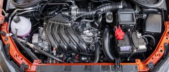
The VAZ-2115 has a gasoline engine, four-cylinder, in-line, four-stroke, with an overhead camshaft, eight-valve. The cylinders operate according to the following scheme: 1–3–4–2, counting from the crankshaft pulley. The system is powered through electrically controlled distributed fuel injection.
Fig.1 VAZ 2115 car engine
- coolant supply pipe;
- engine cylinder complex;
- thermostat;
- coolant temperature sensor;
- outlet pipe;
- engine cylinder head plug;
- engine cylinder head cover;
- fuel pressure level regulator;
- oil filler cap;
- throttle cable;
- throttle assembly;
- idle air control;
- throttle position sensor;
- receiver;
- rear cover of the gas distributor drive;
- front cover of the gas distributor drive;
- injector;
- fuel rail fitting plug;
- fuel ramp;
- intake manifold;
- right intake manifold support bracket;
- generator drive pulley;
- Oil filter;
- crankshaft position sensor;
- oil pan;
- intake manifold;
- connecting rod;
- crankshaft;
- intake manifold support bracket left;
- flywheel.
The engine, together with the clutch and gearbox, form a power unit in the engine compartment - a block on three rubber-metal supports.
The cylinder block is made of cast iron. The nominal diameter is 82 mm, it can be increased by 0.4 or 0.8 mm during repairs. The cylinder class marking is marked on the bottom plane in Latin letters according to the cylinder diameter in millimeters. The permissible level of cylinder wear is 0.15 mm per diameter.
The cylinder block contains five bearing supports, which are bolted to the block. The covers are not interchangeable, since the holes for the bearings are modified in the assembly with the covers. To distinguish them, they are marked on the outside with marks. Thrust half-rings in the middle support prevent axial displacement of the crankshaft.
There is a steel-aluminum half-ring installed in the middle, and a yellow metal-ceramic one at the back. In this case, their grooves face the crankshaft. If the crankshaft play exceeds 0.35 mm, the half rings should be replaced.
Thin-walled shells for connecting rod and main bearings are made of steel-aluminium. The main upper bearings of the first, second, fourth and fifth supports have a groove on the inner surface. The lower main bearing and the upper bearing of the third bearing are without grooves, just like the connecting rod bearings.
The crankshaft is made of high strength cast iron and has journals: main and connecting rod. The shaft has eight counterweights cast with the shaft. Oil is supplied from the main crankpins to the connecting rod journals through drilled channels. The channel entrances to the shaft cheeks are closed with plugs. The channels also serve for oil purification: the rotation of the crankshaft throws resins and solid particles towards the plugs under the influence of centrifugal forces. When dismantling the crankshaft, it is advisable, and before balancing it is simply necessary, to clean these channels from accumulated deposits. The plugs cannot be reused.
The camshaft drive pulley is keyed on the crankshaft at the front end. The generator drive pulley is also attached to it, which serves as a shaft vibration damper.
The flywheel is attached to the rear end of the shaft through a washer with six bolts. The flywheel is cast from cast iron and has a steel toothed ring, which serves as the engine starter.
The connecting rods are made of steel. Their cross-section is an I-beam. The connecting rods are processed together with the covers. In order not to be confused during assembly, the cylinder number is stamped on the covers. A steel-bronze bushing is pressed into the upper head of the connecting rod.
The piston pin is made of steel, tubular in cross-section. The finger rotates freely on the bosses (floating type) and is secured with locking spring rings to prevent it from falling out. They are located in grooves on the piston bosses.
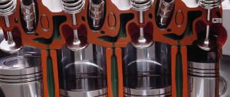
The piston is made of aluminum alloy. The piston skirt has a complex shape: conical in longitudinal section and oval in cross section. Three grooves are machined for the piston rings in the upper part of the piston. There are drillings in the oil ring groove that also serve to supply oil to the piston pin. The hole under the piston pin is offset by 1 mm from the diametrical plane; when installing the piston, you need to orient yourself along the arrow on its bottom: the direction towards the shaft pulley.
In order to reduce imbalance, engine pistons in the crank mechanism are selected based on mass: the spread should be no more than 5 g.
The piston rings are located in the grooves of the piston. The upper rings are compression. These rings prevent gas from escaping into the crankcase and provide heat transfer to the cylinder from the piston. The lower ring is an oil scraper ring. The oil collected from the cylinder walls is transferred to the holes in the piston bosses and lubricates the piston pin.
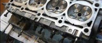
The cylinder head is made of aluminum alloy and is common to all cylinders. It is centered on two bushings. Fastening to the block is carried out with ten screws. A metal-reinforced non-shrink gasket is installed between the head and the block. Its reuse is not permitted.
There are five supports located at the top of the cylinder head. The camshaft supports are detachable, and their holes are machined in assembly with the front and rear bearing housings.
The camshaft is made of cast iron. The design of the shaft is five-bearing. The camshaft is driven into rotation from the crankshaft by a toothed belt. There are marks on the toothed pulleys for proper installation. If the mark of the crankshaft pulley corresponds to the mark of the oil pump housing, then the mark of the camshaft pulley corresponds to the bent antenna of the rear cover of the gas distributor drive.
The guide bushings and valve seats are pressed into the cylinder head. The holes in the bushings are finalized after pressing. Grooves for lubrication are cut on the inner surface of the bushings: along the entire length of the intake valves, and up to half the length of the exhaust valves. Oil reflective caps placed on the bushings are made of oil-resistant rubber.
The valves are made of steel. The exhaust valves have heads made of heat-resistant steel. They are arranged in a row, at an angle to the plane in which the cylinder axes lie. The exhaust valve plate is narrower than the intake valve. The washers that regulate the valve clearance are made of 20X steel. In order to increase their wear resistance, the surface is pre-nitrocemented.
The pushers are made in the form of cylindrical cups; they move in the holes of the cylinder head and rest on the ends of the valves. In order to increase wear resistance, the surface that comes into contact with the valve is carburized. The rotation of the pushers during engine operation is carried out by shifting the cam axis from the pusher axis by 1 mm.
The valve closes under the action of springs. They rest with their lower ends on the washer, and the upper plate is held in place by breadcrumbs. Their shape is a truncated cone, and the inner surface is resistant flanges that fit into the grooves on the valve stem.
Combined engine lubrication is used: the connecting rod and main bearings and the camshaft journal-support pairs are lubricated under pressure; splashing of oil onto the cylinder walls (and further to the pins and piston rings), in the pushrod-camshaft cam pair and to the valve stems. The remaining components are lubricated by gravity.
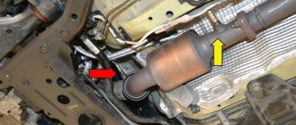
The oil pump in the VAZ-2115 car engine is gear-type, with a pressure reducing valve, internal gearing. The pump is mounted in a housing attached to the cylinder block. The drive gear (smaller) is mounted on two shaft flats at the front end.
The oil receiver is bolted to the pump housing and the bearing cover (second main). The oil filter is non-separable, full-flow, with anti-drainage and bypass valves.
Crankcase ventilation is a closed circuit, with forced removal of gas through an oil separator.
For an overview of the engine characteristics of the VAZ-2115 car, watch the video:
Varieties of VAZ 2115
| Automobile | Option code | Body type | Execution | engine's type | Toxicity standards | Dashboard | Controller | Note |
| VAZ-2115-01 | 10 —> 05.02 | sedan | norm | 21083-60 carburetor with contactless ignition system | R83 | 2114 | carburetor 21083-31 | basic equipment for the domestic market |
| 11 —> 03.02 | sedan | norm | 21083-53 carburetor with contactless ignition system | R83 | 21083 | carburetor 21083 | additional equipment for the domestic market with electric door locks and electric windows | |
| 13 —> 03.02 | sedan | norm | 21083-53 carburetor with contactless ignition system | R83 | 21083 | carburetor 21083 | additional equipment for the domestic market with electric windows | |
| 14 —> 03.02 | sedan | norm | 21083-60 carburetor with contactless ignition system | R83 | 2114 | carburetor 21083-31 | additional equipment for the domestic market | |
| 15 —> 03.02 | sedan | norm | 21083-53 carburetor with contactless ignition system | R83 | 21083 | carburetor 21083 | additional equipment for the domestic market without electric door locks and electric windows | |
| VAZ-2115-20 | 10 | sedan | standard | 2111-86 with distributed fuel injection | R83 | 2114 | 2111-1411020-70 2111-1411020-71 2111-1411020-72 | basic equipment for the domestic market |
| 11 | sedan | standard | 2111-86 with distributed fuel injection | R83 | 2114 | 2111-1411020-70 2111-1411020-71 2111-1411020-72 | optional equipment for the domestic market with heated seats | |
| 12 | sedan | standard | 2111-86 with distributed fuel injection | R83 | 2114 | 2111-1411020-70 2111-1411020-71 2111-1411020-72 | additional equipment for the domestic market without electric door locks and electric windows | |
| 13 | sedan | standard | 2111-86 with distributed fuel injection | R83 | 2114 | 2111-1411020-70 2111-1411020-71 2111-1411020-72 | additional equipment for the domestic market with heated seats without electric door locks and electric windows | |
| 110 | sedan | standard | 2111-86 with distributed fuel injection | Euro-2 | 2114 | 2111-1411020-70 2111-1411020-71 2111-1411020-72 | basic equipment for the foreign market | |
| 119 | sedan | standard | 2111-86 with distributed fuel injection | R83 | 2114 | 2111-1411020-70 2111-1411020-71 2111-1411020-72 | additional equipment for the foreign market without neutralizer and immobilizer | |
| 130 | sedan | standard | 2111-74 with distributed fuel injection | Euro-3 | 2114 | 2111-1411020-50 | additional equipment for the foreign market with phase sensor and rough road sensor | |
| VAZ-2115-21 | 10 | sedan | norm | 2111-86 with distributed fuel injection | R83 | 2114 | 2111-1411020-70 2111-1411020-71 2111-1411020-72 | basic equipment for the domestic market |
| 12 | sedan | norm | 2111-86 with distributed fuel injection | R83 | 2114 | 2111-1411020-70 2111-1411020-71 2111-1411020-72 | additional equipment for the domestic market | |
| 21 | sedan | norm | 2111-86 with distributed fuel injection | R83-02 | 2114 | 2111-1411020-60 2111-1411020-61 2111-1411020-62 | additional equipment for the domestic market with a neutralizer | |
| 110 05.02 | sedan | norm | 2111-86 with distributed fuel injection | Euro 2 | 2114 | 2111-1411020-40 | basic equipment for the foreign market | |
| VAZ-2115-22 | 10 | sedan | norm | 2111-86 with distributed fuel injection | R83-02 | 2114 | 2111-1411020-60 2111-1411020-61 2111-1411020-62 | basic equipment for the domestic market |
| 11 | sedan | luxury | 2111-86 with distributed fuel injection | R83-02 | 2114 | 2111-1411020-60 2111-1411020-61 2111-1411020-62 | additional equipment for the domestic market | |
| 110 | sedan | luxury | 2111-86 with distributed fuel injection | Euro 2 | 2114 | 2111-1411020-40 | basic equipment for the foreign market | |
| 119 | sedan | luxury | 2111-86 with distributed fuel injection | R-83 | 2114 | 2111-1411020-70 2111-1411020-71 2111-1411020-72 | additional equipment for the foreign market without neutralizer and immobilizer | |
| 130 | sedan | luxury | 2111-74 with distributed fuel injection | Euro 3 | 2114 | 2111-1411020-50 | additional equipment for the foreign market with phase sensor and rough road sensor |
Diagram of VAZ 2115 injector 8 valves
The front part of the electrical circuit VAZ 2115 injector 8 valves
| Position number on the diagram | Explanation of position |
| 1 | Headlights; |
| 2 | *Electric motor for headlight wipers |
| 3 | Fog lights |
| 4 | DTV VAZ 2115 |
| 5 | Signal |
| 6 | Engine compartment lamp switch |
| 7 | Motor cooling fan motor |
| 8 | Generator |
| 9 | Emergency oil level sensor |
| 10 | Antifreeze meter |
| 11 | Front brake pad wear gauge |
| 12 | **Window washer wire terminal block |
| 13 | Windshield washer nozzle pump |
| 14 | *Headlight washer pump |
| 15 | Rear window washer pump terminal block |
| 16 | Oil pressure alarm sensor |
| 17 | Engine compartment lamp |
| 18 | Terminal block for connecting to a bundle of wires of the VAZ 2115 engine control system of the VAZ 2111 model or to the sensor for connecting a fan with a VAZ 2115 engine of the VAZ 21083 model |
| 19 | Windshield wiper motor |
| 20 | Starter |
| 21 | Engine ignition system wiring harness terminal block |
| 22 | TOZH indicator sensor |
| 23 | Reversing light switch |
| 24 | Emergency brake fluid level meter |
| 25 | Battery |
| 26 | Emergency antifreeze level meter |
| 27 | Fog light switch |
| 28 | Fuse box VAZ 2115 |
| 29 | Brake light switch |
| 30 | Carrying cartridge |
| 31 | Headlight hydrocorrector scale light |
| 32 | Handbrake control switch |
| 33 | Terminal block for backlight bulb |
| 34 | Instrument lighting switch |
| 35 | Steering wheel switch |
| 36 | Emergency button |
| 37 | Front seat heater switch |
| 38 | Egnition lock |
| 39 | Rear fog light line fuse |
| 40 | Front seat heating line fuse |
| 41 | Door lock line fuse |
| 42 | Front ashtray light |
| 43 | Ignition switch |
| 44 | Cigarette lighter |
| 45 | Board light bulb |
| 46 | Front light switch |
| 47 | Heater fan electric motor |
| 48 | Additional heater motor resistance |
| 49 | Heater fan switch |
| 50 | Heater fan switch light |
| 51 | Heater control light |
| 52 | Electric windows of the front doors of VAZ 2115 |
| 53 | Right front door power window switch |
| 54 | Front door locking gear motor |
| 55 | Right front speaker wires |
| 56 | Rear door locking gear motor |
| 57 | Right rear speaker wires |
| 58 | ECU for blocking door locks of VAZ 2115 |
| 59 | Radio connection cables |
| 60 | *Headlight wiper switch |
| 61 | Rear window defroster switch |
| 62 | Rear fog light switch |
| 63 | Terminal block for connecting the right front seat heater |
| 64 | Rear fog light switch |
| 65 | Right front seat heater switch |
| 66 | *Fog switch |
| 67 | Dimensions switch |
| 68 | Left front seat heater switch |
| 69 | Terminal block for connecting the left front seat heater |
| 70 | Left front speaker connection wires |
Diagram of VAZ 2115 injector 8 valves rear part
| Position number on the diagram | Explanation of position |
| 71 | Left front door power window switch |
| 72 | Right front door power window switch |
| 73 | left rear speaker wires |
| 74 | side turn signals |
| 75 | switch on the front door pillars |
| 76 | switch on the rear door pillars |
| 77 | central interior light |
| 78 | front interior light |
| 79 | terminal block for connecting a gasoline pump |
| 80 | trunk light switch |
| 81 | instrument cluster VAZ 2115 |
| 82 | trunk light |
| 83 | signaling unit for on-board control system VAZ 2115 |
| 84 | minibus |
| 85 | terminal block for connecting the motor control system |
| 86 | rear exterior lights |
| 87 | rear interior lights |
| 88 | terminal block for connecting the rear window defroster |
| 89 | room lighting light |
| 90 | additional brake signal in the spoiler |
| Position number on the diagram | Explanation of position |
| A | headlights and headlight wipers |
| B | cigarette lighter |
| IN | mounting block, dashboard, ignition switch, windshield wipers, etc. VAZ 2115 |
| G | rear fog light switch |
| D | hazard warning button |
| E | gear motor for power windows and door locks |
| AND | central interior light |
In the twist of the instrument panel wires, the other ends of the white wires are soldered together and connected to the light switch of the instrument cluster (excluding the white wire from plug “4”, block “X2” of fuse box 28 to block 83 of the on-board control system indication). The other ends of the black wires are soldered at a point connected to ground. The other ends of the yellow wires with a blue stripe are soldered to a point and connected to plug 4 of block “X1” of the fuse box. The other ends of the white wires with a red stripe are connected to a point and connected to plug 10 of block “X4” of the fuse box. The other ends of the orange wires are soldered together and connected to plug 3 of the “X4” block of the fuse box.
- * - produced on parts of manufactured cars;
- ** - on vehicles of different configurations, one common pump and solenoid valves for headlight and windshield washing can be installed. Then the blocks 12 are connected to the washer pump, and the wires connected to the pumps 13 and 14 are connected to the corresponding solenoid valves.
Healthy ! VAZ 2114 diagrams.
Summary electrical diagram of VAZ 2115 injector 8 valves
Connection diagram for VAZ 2115 luxury version
The front part of the wiring diagram for the VAZ 2115 luxury version
| Position number on the diagram | Explanation of position |
| 1 | Flashlight |
| 2 | *fap wiper gear motor |
| 3 | fog lights; |
| 4 | DTV VAZ 2115 |
| 5 | signaling |
| 6 | engine light switch |
| 7 | engine cooling fan motor |
| 8 | generator |
| 9 | emergency oil level meter |
| 10 | antifreeze level meter |
| 11 | front brake pad wear gauge |
| 12 | **window washer pump terminals |
| 13 | windshield washer pump |
| 14 | *headlight washer pump VAZ-2115 |
| 15 | terminals for connecting the rear window washer pump |
| 16 | low oil pressure sensor |
| 17 | engine compartment light |
| 18 | terminal block for connecting to a bundle of wires of the engine control system |
| 19 | windshield wiper motor |
| 20 | starter VAZ 2115 |
| 21 | terminal block, connections to a bundle of wires of the ignition system on carburetor engines |
| 22 | antifreeze heat indicator meter |
| 23 | rear traffic light switch |
| 24 | brake fluid level indicator sensor |
| 25 | source of electricity |
| 26 | antifreeze level indicator meter |
| 27 | Relay for connecting front fog lights |
| 28 | fuse box VAZ 2115 |
| 29 | brake light switch |
| 30 | portable socket |
| 31 | hydrocorrector lighting bulb |
| 32 | handbrake connection signal light switch |
| 33 | terminal block for turning on the backlight bulb |
| 34 | instrument light switch |
| 35 | steering column switch |
| 36 | hazard warning light switch |
| 37 | Relay for the front seat heating element |
| 38 | ignition lock VAZ 2115 |
| 39 | rear fog lamp line fuse |
| 40 | front seat heating elements line fuse |
| 41 | door lock line fuse |
| 42 | front ashtray light bulb |
| 43 | ignition switch VAZ-2115 |
| 44 | cigarette lighter |
| 45 | glove compartment light bulb |
| 46 | glove compartment light switch; |
| 47 | heater fan motor |
| 48 | additional resistance of the stove motor |
| 49 | heater fan switch |
| 50 | heater switch light |
| 51 | heater control lamp |
| 52 | front door electric window motor |
| 53 | ESP switch of the right front door (located in the right door) |
| 54 | motor gearboxes for locking front door locks |
| 55 | wires for connecting to the right front speaker |
| 56 | motor gearboxes for rear door locks |
| 57 | wires for connecting to the right rear speaker |
| 58 | ECU for blocking door locks of VAZ 2115 |
| 59 | wires for connecting to the radio |
| 60 | headlight wiper switch |
| 61 | rear window heating element switch |
| 62 | connector for connecting rear fog lamps |
| 63 | terminal block for connection to the heating element of the right front seat |
| 64 | rear fog light switch |
| 65 | right front seat heating element switch |
| 66 | *fog light switch |
| 67 | headlight switch |
| 68 | left front seat heating element switch |
| 69 | terminal block for connection to the left front seat heating element |
| 70 | wires for connecting to the left front speaker |
Rear part of the wiring diagram for the VAZ 2115 luxury version
| Position number on the diagram | Explanation of position |
| 71 | left front door power window switch (located in the left door) |
| 72 | Right front door power window switch (located in the left door) |
| 73 | wires for connecting to the left rear speaker |
| 74 | side turn signals |
| 75 | light switches on the front door pillars |
| 76 | light switches on the rear door pillars |
| 77 | lamp |
| 78 | individual interior light lamp VAZ 2115 |
| 79 | terminal block for connecting to a bundle of electric fuel pump wires |
| 80 | trunk light switch |
| 81 | instrument panel VAZ 2115 |
| 82 | trunk light bulb |
| 83 | display unit for on-board control structure of VAZ 2115 |
| 84 | route ecu |
| 85 | terminal block for connecting a bunch of wires for motor control mode |
| 86 | rear exterior lights |
| 87 | rear interior lights |
| 88 | terminal blocks for connection to the rear window heating element |
| 89 | room lighting fixtures |
| 90 | additional brake light located on the spoiler |
| Method of numbering terminal blocks in blocks | |
| A | block headlights and headlight wipers; |
| B | cigarette lighter |
| IN | fuse box, instrument panel, ignition switch, windshield wiper and other electrical equipment components (terminal blocks with a different number of terminals have the same numbering method); |
| G | Rear fog light connector |
| D | emergency light switch |
| E | gear motor for power windows and gear motor for door locks |
| AND | interior light lamp |
* Mounted on some manufactured cars.
* On cars of different versions, 1 common washer pump and electromagnetic chokes for washing headlights and windshield can be installed. Then terminal blocks 12 are connected to the washer pump, and the wires connected to pumps 13, 14 are connected to the corresponding electromagnetic chokes.
In the bundle of instrument panel wires, the other ends of the white wires are soldered into one point, which is connected to the instrument lighting switch (except for the white wire, from terminal block “4” of block “X2” of fuse box 28 to block 83 of the on-board control system display). The other ends of the black wires are also soldered to the points connected to the body. The other ends of the yellow wires with a blue stripe are connected to the point attached to plug “4” of block “X1” of the fuse box. The other ends of the white wires with a red stripe are connected at the point connected to the “10” plug of the “X4” block of the fuse box. The other ends of the orange wires are connected at the point connected to plug “3” of block “X4” of the fuse box.
Integrated connection diagram for VAZ 2115 luxury version
Engine diagram VAZ 2115 injector
Here is a diagram of a VAZ 2115 engine with an injector of the VAZ 2111 model with a volume of 1.5 liters. This is an electrical diagram of a VAZ 2115 8 valve engine.
| Position number on the diagram | Explanation of position |
| 1 | spark plug 4 pots |
| 2 | spark plug 3 cylinders |
| 3 | candle for igniting the second pot |
| 4 | spark plug cylinder 1 |
| 5 | ignition module VAZ 2115 |
| 6 | diagnostic connector block |
| 7 | 1 pot sprayer |
| 8 | second pot sprayer |
| 9 | injector 3 cylinders |
| 10 | 4 pot nozzle |
| 11 | ECU VAZ 2115 |
| 12 | fuel pump connection relay |
| 13 | to the electric engine radiator fan |
| 14 | connector for connecting the engine radiator electric fan |
| 15 | main switch of the engine control system |
| 16 | DMRV VAZ 2115 |
| 17 | dpdz |
| 18 | dtozh |
| 19 | idle air control |
| 20 | canister purge throttle |
| 21 | dpkv |
| 22 | dd |
| 23 | oxygen sensor |
| 24 | to the ignition switch |
| 25 | ECU immobilizer VAZ 2115 |
| 26 | immobilizer sensor with indicator |
| 27 | car speed meter; |
| 28 | additional terminal connector |
| 29 | to the battery positive |
| 30 | terminal block for connecting to the car's electrical network |
| 31 | fuel pump |
| 32 | to control the fuel reserve (on the instrument panel) |
| 33 | to the gasoline level indicator |
| F1 | fuse for ECU and engine control system lines |
| F2 | ECU fuse |
| F3 | fuel pump line fuse |
On cars of the last years of production, changes were added to the engine control system: a DPRV, an ignition coil and a diagnostic connector block with digital pin numbering were installed (similar to the engine control system 11183). The rating of fuses FI and F2 has been changed to 7.5 A.
Motor maintenance
When the design and main technical characteristics inherent in the VAZ 2114 engine have been reviewed, it is necessary to consider maintenance and provide answers to questions that motorists are increasingly asking.
Maintenance
If you believe the plant, the manufacturer, the VAZ 2114 engine must be serviced every 12-15 thousand kilometers. It depends on what marking the motor is installed on the vehicle. Maintenance scheme for all engines installed on the “fourteenth” model:
- At the first maintenance, the oil, oil filter and air filter element are replaced, as well as the functionality of all systems is checked.
- The second maintenance is done after 12,000 km. In this case, it is necessary to change the oil and oil filter element.
- Third maintenance – 25,000 km, replacing not only the oil, but also the air filter, and ongoing repair of faults.
- After 45,000 km, it is necessary to replace the timing belt and roller so that the VAZ 2114 engine does not have to be overhauled.
Engine control circuit 11183 l.6 liter VAZ 2115
Here is an electrical circuit for controlling a 1.6-liter model 11183 injection engine installed on VAZ 2115 cars.
| Position number on the diagram | Explanation of position |
| 1 | Spark plug 4 pots |
| 2 | spark plug cylinder 3 |
| 3 | spark plug 2 pots |
| 4 | 1 pot spark plug |
| 5 | Ignition solenoid |
| 6 | diagnostic connector |
| 7 | 1 cylinder sprayer |
| 8 | nozzle 2 pots |
| 9 | sprayer 3 cylinders; |
| 10 | fourth cylinder injector |
| 11 | VAZ 2115 controller |
| 12 | Gasoline pump connection connector |
| 13 | to the engine electric fan |
| 14 | motor fan connection connector; |
| 15 | main motor control switch |
| 16 | dmrv |
| 17 | dpdz |
| 18 | dtozh |
| 19 | empty control |
| 20 | canister purge throttle |
| 21 | dpkv |
| 22 | knock sensor |
| 23 | oxygen concentration meter |
| 24 | to the ignition switch |
| 25 | ECU immobilizer VAZ 2115 |
| 26 | immobilizer sensor with warning light |
| 27 | car speed meter |
| 28 | additional terminal block |
| 29 | to the battery positive; |
| 30 | dprv |
| 31 | terminal block for connecting to the car's electrical network |
| 32 | gasoline pump |
| F1 | fuse for ECU and engine control system lines |
| F2 | ECU fuse |
| F3 | fuel pump circuit fuse |
Local electrical circuits of VAZ 2115
Cooling diagram for VAZ 2115
High-quality color diagram of the cooling system of the engine 2111 of the VAZ 2115. It shows the cooling diagram of the VAZ 2115 injector 8 valves. Dual-circuit cooling system with thermostat. The cooling system is liquid, closed type, with forced circulation.
| Position number on the diagram | Explanation of position |
| 1 | Expansion tank |
| 2 | cork |
| 3 | vapor pipe |
| 4 | tube connecting the thermostat and expansion tank |
| 5 | dtozh VAZ 2115 |
| 6 | air damper assembly |
| 7 | radiator inlet pipe |
| 8 | coolant outlet pipe |
| 9 | left radiator tank |
| 10 | right radiator tank |
| 11 | drain plug; |
| 12 | heat exchanger core |
| 13 | fan diffuser; |
| 14 | fan blades |
| 15 | electric motor |
| 16 | pump toothed pulley |
| 17 | pump impeller |
| 18 | timing belt |
| 19 | stove outlet pipe; |
| 20 | pump supply hose |
| 21 | valve |
| 22 | stove heat exchanger |
| 23 | antifreeze drain pipe from the throttle pipe |
| 24 | tube supplying antifreeze to the throttle pipe |
| 25 | antifreeze temperature indicator sensor |
| 26 | outlet hose |
| 27 | heater supply hose |
| 28 | thermostat VAZ 2115 |
| 29 | antifreeze level meter |
Block head and timing device
All front-wheel drive cars of the VAZ family, be it 2109, 2110 or 2114, have one cylinder head, common to all cylinders. They are mounted to the block using ten screws. During installation, a metal gasket is placed under it. This gasket is for single use and cannot be reused. There are five camshaft bearings at the top of the cylinder head.
The camshaft of the engine of the VAZ-2109 car has the index 21083. Some engines are equipped with 2110 or 2111 shafts; their design is slightly different from 21083, which allows for an increase in engine power. The shaft is cast from cast iron, there are five supports and eight cams on it that open the valves.
Seats are pressed into the cylinder head, as well as valve guides. On the inside of the bushings there are grooves for supplying lubricant; the bushings are closed on top with oil deflector caps.
The valves are made of steel, and the intake head is made of heat-resistant steel. They are mounted obliquely in one row. The inlet valve has a larger diameter than the outlet valve. The gaps between the valves and camshaft cams are adjusted using shims that have increased wear resistance.
Pushers are metal cups moving in the cylinder head holes. To improve wear resistance, the surface in contact with the ends of the valve stems is cemented.
Schemes VAZ-2115-01
Electrical diagram for connecting the VAZ-2115-01 generator model 37.3701
| Position number on the diagram | Explanation of position |
| 1 | battery |
| 2 | generator VAZ-2115-01 model 37.3701 |
| 3 | relay and fuse box |
| 4 | battery charge control located on the instrument panel |
| 5 | ignition switch |
Generator voltage regulator test circuit
| Position number on the voltage regulator diagram | Explanation of position |
| 1 | battery |
| 2 | regulator ground output |
| 3 | generator voltage regulator 37.3701 VAZ-2115 |
| 4 | terminal "Ш" |
| 5 | terminal "B" |
| 6 | control 1 - 3 W 12 volts |
When 12V voltage is applied to terminals “B” and ground, the light bulb should light up. When a voltage of 15-16V is applied to terminals “B” and ground, the light bulb should not light up. If the light bulb lights up in two cases, then there is a breakdown in the regulator. If it does not light up, there are two options: there is a break in the regulator or there is no contact between the brushes and the terminals of the regulator.
Starter connection diagram 29.3708 VAZ-2115-01
| Position number on the starter diagram 29.3708 | Explanation of position |
| 1 | starter 29.3708 VAZ-2115-01 |
| 2 | battery |
| 3 | generator |
| 4 | fuse box |
| 5 | ignition switch |
| P1 | pull-in coil of traction relay |
| P2 | traction relay holding coil |
Scheme of the contactless ignition system VAZ-2115-01
| Position number on the diagram | Explanation of position |
| 1 | spark plugs |
| 2 | distributor sensor |
| 3 | ignition coil |
| 4 | switch VAZ 2115 |
| 5 | carburetor solenoid valve control unit |
| 6 | carburetor solenoid valve |
| 7 | carburetor limit switch |
| 8 | Ignition lock VAZ 2115 |
| 9 | fuse box |
| 10 | speed meter VAZ 2115 |
| 11 | motor blower fan motor |
| 12 | sensor for turning on the engine blower fan |
| A | terminal blocks for connecting to the front bundle of wires |
| B | terminal numbering diagram in the ignition sensor-distributor and speed meter blocks |
| IN | to voltage sources |
| G | to the instrument panel (impulse for tachometer) |
| E | to the instrument cluster (impulse for speedometer) |
Complete set of the contactless ignition system VAZ-2115-01:
- sensor-distributor - 40.3706, 40.3706-01
- switch - 3620.3734, 76.3734, RT1903, PZE4022
- ignition coil - 27.3705, 27.3705-01, 027.3705, ATE-1721, 8352.12, 3122.3705
- spark plugs - A17DVRM, A17DVRM1
- ignition switch - 2110-3704005, KZ-881
Diagram for checking the removed sensor-distributor
| Position number on the diagram | Explanation of position |
| 1 | distributor sensor VAZ 2115-01 |
| 2 | resistance 2 kOhm |
| 3 | voltmeter with a scale of at least 15V and an internal resistance of at least 100 kOhm |
| 4 | terminal connector of the sensor-distributor |
Switch test circuit
| Position number on the diagram | Explanation of position |
| 1 | arrester |
| 2 | ignition coil |
| 3 | switch VAZ 2115 |
| 4 | resistor 0.01 Ohm ÷ 1% not less than 20 W |
| A | to the square pulse generator |
| IN | to the oscilloscope |
Scheme for checking the distributor sensor on a VAZ 2115-01 car
| Position number on the diagram | Explanation of position |
| 1 | distributor sensor |
| 2 | adapter connector with a voltmeter with a scale of at least 15V and an internal resistance of at least 100 kOhm |
| 3 | distributor sensor VAZ 2115-01 |
Rear light diagrams for VAZ 2115-01
| Position number on the diagram | Explanation of position |
| 1 | turn signal lamps |
| 2 | size bulbs |
| 3 | brake lights |
| 4 | fog light bulbs |
| 5 | reverse light bulbs |
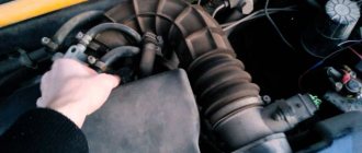
Should high-voltage wires be replaced and when?
No matter how well the armored wires are made, they also have a limited service life. According to current regulations, they must be replaced after every 30,000 km traveled. In practice, many motorists ignore this rule, continuing to travel with wires that have already outlived their useful life.
Such inattention can cause a whole host of problems, including:
- poor ignition;
- overclocking problems;
- engine tripping;
- inability to start the car.
All these troubles are caused by one single factor - an increase in the electrical resistance of the core of high-voltage wires, as a result of which it becomes “more difficult” for the impulse from the coil to reach its destination.
You can check whether you can still drive with the old wires or not - at home.
To do this you need:
- Turn off the ignition.
- Remove one of the armored wires.
- Measure its resistance using a megohmmeter or multimeter in the appropriate mode.
- If the resistance turns out to be equal to or close to the figure indicated on the wire insulation, then it is in good condition, but if it turns out to be greater, then the wire should be replaced.
- Repeat this operation on the remaining three wires.
It should be remembered that if only one of the wires is faulty, then all four should still be replaced.
Also, do not forget about the cleanliness of the contacts of high-voltage wires - they can also cause ignition problems. If oxides are noticeable on the metal tip, they should be cleaned with fine sandpaper or a cloth moistened with kerosene. By following these simple rules for caring for armored wires and replacing them, you can almost completely avoid troubles associated with the ignition system.
Additional diagrams of the VAZ 2115 car
Fuse diagram for VAZ 2115 model 2114-3722.010
Here is an electrical diagram of the internal connections of the mounting block of fuses and relays of the VAZ 2114-3722.010 brand. It shows relays connecting the main consumers of electricity. These relays are presented with their own internal electrical circuits, providing the opportunity for a better understanding of the operation of this device. This diagram shows plug blocks on both sides with their numbers and the numbers of the terminal connectors. Internal number - indicates the number of the terminal connector. The external designation in the form “Ш1”, “Ш2” and so on is the designation of plug connectors.
What is this?
Engine overhaul refers to the work of a master aimed at returning the engine to a state as close as possible to its original state.
In this case, most of the nodes are changed or restored. This type of repair is resorted to when there is a lot of wear on the parts of the unit. The list of work may include grinding the crankshaft journal and camshaft, installing new pistons and springs, and honing the cylinders. If too many engine components are faulty, then it is more advisable to completely replace it.
The following signs indicate that it is time to overhaul the engine on the VAZ-2114:
- The appearance of red, black or dark gray carbon deposits on the spark plugs.
- Increased oil consumption.
- The occurrence of knocking in the engine.
- Increased fuel consumption.
- The appearance of smoky exhaust.
- Bad traction.
- Engine overheating.
- At idle, the engine runs unevenly.
- Reduced power.
Major repairs proceed approximately according to this scheme:
- Preparing the engine for dismantling (disconnecting wires, hoses, gearbox).
- Removing the engine.
- Removal and inspection of the cylinder head.
- Disassembling the unit for diagnostics and cleaning.
- Block boring. Grinding the crankshaft. Application of hone to the cylinder walls.
- Weight distribution of connecting rods, pistons.
- Block assembly.
- Restoring the head (replacing caps and guides, straightening seats).
- Assembling the engine and installing it in the engine compartment.
- Connection.
- Functionality check.