| Installation location | Base size | Power, W |
| Block - headlight | ||
| Further | H1 | 55 |
| Near | H7 | 55 |
| Turn signal bulbs for Lada Vesta | PY21W | 21 |
| DRL lamps (running lights), turn signals | W21/5W | 21 / 5 |
| External rear light | ||
| Bulbs in dimensions, brake light | W21/5W | 21 / 5 |
| Turn signals | WY16W | 16 |
| Rear light internal | ||
| Reverse | W16W | 16 |
| parking lights | W5W | 5 |
| Lamps in PTF Lada Vesta | H16 | 19 |
| Turn signal indicator | W5W | 5 |
| License plate light | W5W | 5 |
| Glove compartment lighting | W5W | 5 |
| Luggage compartment lighting | W5W | 5 |
| Front door sill illumination | W5W | 5 |
Installation of flexible LED DRLs in the headlights of LADA cars
Have you heard about flexible LED daytime running lights (DRLs or DRLs), which are designed for self-installation in car headlights?
Such tuning of head optics does not require large expenses and can significantly transform the car. Let's look at this process in detail. Required
: flexible DRLs (can be found among popular Aliexpress products, price about 400 rubles), the set includes four U-shaped fasteners per strip.
The following shows the process of installing flexible DRLs in Lada XRAY headlights. On other LADA models (Vesta, Largus, Granta, Priora, Kalina, etc.) the process is performed similarly. There are examples in the comments below.
Installation
2. Remove the glass from the headlight (using the example of XRAY, Priora or Granta/Kalina 2).
3. Removed the headlight mask (attached with latches).
4. Make holes (with a thin drill or a heated paper clip) for self-tapping screws in the places where the U-shaped fasteners will be installed.
If there are not enough fasteners, you can make two holes in the headlight mask and secure the flexible DRLs with fishing line. Or use super glue.
We make a hole in the back of the headlight for the wires.
Light inside turn signals
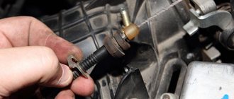
The turn signal light of the Lada Vesta is built into the socket, so before you begin replacing it, you need to turn it to the left and then carefully pull it out. To do this, use a flag attached directly to the cartridge. To unscrew the light bulb itself, you need to press it a little and at the same time turn it counterclockwise. It will come out of the socket, and you can install new lighting. After replacing in the reverse order, the cartridge must be secured with a sealing gasket. After replacing any light bulb in the headlight unit, it is recommended to check compliance with the technical instructions. If necessary, lighting should be adjusted.
Connection
It is recommended to use a DRL control controller (you can find it in the same catalog for 170 rubles). This block will extend the life of LEDs. The connection is made according to the following diagram:
A simpler option using KREN 8B:
Let us remind you that we previously considered other methods of installing LED DRLs in the headlights of LADA cars (report No. 1, report No. 2). An easier way to tune headlights is to install LEDs instead of lamps. What do you think about this?
Share on social networks:
Found an error? Select it and press Ctrl+Enter..
Source
How to increase the service life of electrical equipment
To extend the life of standard wiring, it is recommended to perform certain actions. Periodically check the tightness of the plugs - during active driving, the plastic fasteners may wobble, which can cause a short circuit. Before active use, treat all detachable connections with special oil. This will prevent their oxidation and deterioration of impulse transmission.
Every year check the condition of the wire braiding - during operation there are strong temperature changes on the main line - this dries out the insulation and stimulates short circuits.
Installing LEDs instead of lamps in LADA headlights (DRLs)
On modern Lada cars (Vesta, Granta or Kalina 2), a double-filament lamp (W21/5W) is used as dimensions and daytime running lights (DRL). A small tuning of the optics is to get rid of the yellowness of the standard incandescent lamps. To do this, LEDs are installed instead of them, having previously been modified in a certain way.
Before replacing, you should find out what the polarity or pinout is in the DRL socket. On modern Lada models the polarity is non-standard:
- there should be a “ground” on one side of the lamp (can be one common contact or two);
- on the other - “plus” for dimensions and “plus” for DRLs.
When buying LEDs, make sure that the polarity on the base matches the polarity in the socket (look for LEDs W21/5W, P27/7W (3157, 7443) with the abbreviation SRCK or SK type). Many car enthusiasts, not finding these, bend the antennae in the required order (connecting the “ground” on one side, and bringing the two “pluses” to the other). Before installing LEDs in headlights, check their operation using a battery.
Attention! Such tuning can damage a fuse, an additional body electronics unit or wiring. In this case, the vehicle warranty is not valid.
The process of replacing lamps with LEDs is also shown in the video:
Instead of LED, we recommend installing W21/5W white halogen lamps.
Let us remind you that the process of replacing DRL lamps and dimensions is available in detail separately for Lada Vesta and Lada Granta and Kalina 2. Look for other improvements in the “Tuning” menu.
Share on social networks:
Found an error? Select it and press Ctrl+Enter..
Source
What to buy?
One of the Drayvovites, who is known in the community under the nickname 22KAZAK, carefully studied this issue before replacing the lamps in all the above components on his Lada Vesta Altai sedan. As a result, he came to the conclusion that it is possible to replace factory lamps with an analogue one, but only if you purchase tested, certified products and proper installation, so this point must be monitored especially carefully.
So, to replace you will need:
- Low beam – LED lamps OPTIMA CL-6 LED HEADLIGHT. Installing such lamps will also require the purchase of universal rubber covers for the headlamp.
- Dimensions and DRLs are MTF W21/5W LEDs. They fully comply with the requirements and match the polarity.
- License plate light – PHILIPS.
During the installation process, questions usually do not arise and you can do everything yourself. The main thing is to correctly calculate the polarity when installing lamps in side lights/DRLs. If you are not confident in your abilities and knowledge, it is strongly recommended to consult an auto electrician or entrust the work to him.
Installation of LED moldings (DRL+turn signals) in the front bumper of LADA cars
X-shaped moldings in the front bumper of LADA cars are part of the company’s corporate DNA. Do you want to highlight your uniqueness? Instead, install LED elements with daytime running lights (DRL) and dynamic turn signals.
Purpose
. LED daytime running lights with dynamic turn signal repeaters will emphasize the uniqueness of your car, making it more attractive and noticeable on the road.
Installation
. A set of LED elements (popularly “bumper sticks”) is installed to replace the standard chrome moldings. To remove them, you need to dismantle the front bumper, then unscrew the screws securing the molding (Togh T20), and then release the locking latches (flat-head screwdriver). See how to disassemble the bumper. Install the LED moldings in the reverse order.
- Black
to ground - Yellow
for turn signals - Red
on DRL
Via PC
- Adapter ELM327, you can buy on AliExpress (see product catalog).
- Ddt4all software (download).
How to activate the function
:
- Run ddt4all. Select a port. Select an adapter. Check the box and click Connect.
- In the window that opens, click the button marked with a circle (with a magnifying glass).
- Select search by CAN.
- In the left window, find and select the [EMM] block.
- Below we open “EMM_Lighting -> EMM_Lighting - configuration”
- In the right window we find the parameter “Nbx_rear_tail_with_DRL_CF”
- Enable Expert mode (in the menu at the top, second icon from the left).
- Change the values from 0 to 1.
- Save with the “Send” button or the button located to the right of the set value.
The process is also shown in the video:
Changing the parameters of the center
You can change the following parameters:
- The “BCM” block (on the left), the “Doorlock” function (below the block) and in the same place “Doorlock - Configuration”.
- Enabling “AntiHiJack” in the line “ANTI_HIJACK_CF (-)”, specify the required value, click “TRUE”, “Send”. Initially, AntiHiJack is deactivated on the machine. If you activate it, then with one click on the key fob the car will be disarmed, and with a second click it will be unlocked. When opening a door from the inside, only one door will open, the others will be closed, provided the central locking is activated. You can deactivate the functions by selecting the “FALSE” command and then “Send”.
- Speed threshold for activating a signal about an unlocked door - go to “DOOR_WARNING_SPEED_THRESH_TP (km/h)”, specify the required speed on the right and click “Send”.
- Changing the speed threshold for automatic central locking - go to “LWS_SPEED_THRESH__CF (km/h)”, specify the required speed, click “Send”.
- Auto-arming timeout (triggered when the system is turned off by the key fob or if the door is not closed) for this period of time in “AUTO_RELOCK_TIMEOUT_CF (min)” specify the required number of minutes, then click “Send”.
Via phone
- Bluetooth adapter ELM327.
- Pyren script (download).
- DDT database (download).
- SL4A (Python) on Android.
- Launch _pyren_launcher.ry
- Select the connection type, then Start
- Enter the cmd command to access the extended menu
Next, find the corresponding item in the menu (the exact name is still unknown).
Let's remember that we previously told you how you can do the same:
Share on social networks:
Found an error? Select it and press Ctrl+Enter..
Source
Installation of LEDs in Vesta daytime running lights.
Today I want to talk about installing LED lamps instead of standard incandescent lamps for daytime running lights. LED DRLs significantly improve the appearance of the car, are more visible on the highway and have a longer service life compared to incandescent lamps. As a result, almost all new cars already have standard LED lighting. Vesta was less fortunate in this sense.
But who’s stopping you from changing it if you really want beauty and durability? LEDs are more than available, even in auto stores, even in China. Installation is not difficult, because it is not the ill-fated xenon, and is accessible to anyone who has at least once changed the light bulbs in their car. All this is true, if you do not delve into the details. But, since the car is new, you still have to delve into it, because if something goes wrong, then you yourself will be responsible for your actions. So let's put our itchy hands in the back pockets of our trousers for now.
First of all, you need to consider the following nuances:
- To ensure that LEDs do not look dim and perform their function properly, you need a light beam of 500-600 lumens, and for this you need to install fairly powerful models of 4-6 Watts. From a four-watt LED you will get about 2 W of heat, which needs 40-50 sq.cm to dissipate. areas made of good heat-conducting material. You will not find either one or the other in the DRL compartment of the standard Vesta headlight. Therefore, if you do not want the headlight to melt during operation, you need to think through heat sinks.
- The resistance of the diodes is higher, so it makes sense to replace fuses F16 and F17, but there is still a high probability of burning the electronics unit and ending up with a tidy sum, because the case, of course, will not be covered under warranty. Before purchasing LED lamps, I highly recommend reading customer reviews, especially if the lamps are purchased in China.
- It is necessary to pay attention that some LED lamps have a polarity and they need to be installed in accordance with it, otherwise the same body electronics unit or, at best, the fuse will have to be replaced..
- And finally, the headlight unit with heat sinks will not be sealed, moisture getting into the headlight is more than possible with all the consequences. Sealing needs to be considered.
How to remove protection?
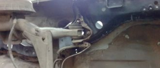
To independently remove the protection (reboot) in the EMM block, AVTOVAZ has issued a special instruction. In short, it says that to remove the blocking, it is enough to apply +12 volts to the 3rd contact (free) of the white block of the block for 2-3 seconds with the ignition on, and then reset the errors of the comfort block controller. After this, performance should be restored.
Detailed instructions for removing protection:
- Remove the glove compartment lid to gain access to the comfort unit.
- Connect a connector with a wire at least 50 cm long to the free pin 3 of the white block.
- Apply +12V to the other end, for example from the green wire of the glove compartment lighting block.
- Turn on the ignition for 3 seconds.
- Turn off the ignition and remove the installed circuit, returning everything to its original state.
- Reset the EMM unit errors using a Grade-X scanner (or any other available method).
- Check the functionality of the circuits.
There is a more humane way - you can remove the protection using a special Grade-X scanner, which is now available at official Lada dealers. It is enough to find the corresponding parameters in the list that are responsible for unlocking the right and left sides of the car, respectively. After activation and complete reset of the unit, lighting functionality is usually restored.
Grade-X Scanner
If these instructions do not bring the desired result, this indicates that one or more driver channels are damaged. In this case, there are two options for eliminating the malfunction - repairing the unit or replacing it with a new one. If you are comfortable with a soldering iron, then you can easily figure out the circuit diagram of the unit and, using inexpensive attachments (installing additional relays), cheaply repair the electronics. If it is possible to purchase new driver chips, then repairing the unit will come down to replacing them.
For those interested, we provide sample diagrams for repairs using the installation of an additional relay.
As a conclusion, it is worth noting that interfering with normally functioning car components is always fraught with unexpected problems, and before replacing a simple working light bulb, think 10 times - whether all this will result in expensive repairs and a lot of wasted time.
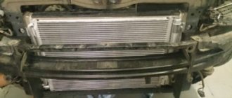
Installation of fog lights and daytime running lights on Lada Vesta
Fog on the road is a frequent occurrence, so it is difficult to imagine a modern car without fog lights (FFL), which increase driving safety in poor visibility.
Lada Vesta is a modern sedan, and the need to equip it with this optics is also obvious, but fog lights are installed by the manufacturer only on top versions of the model, while in the basic configuration, the front bumper only has removable plugs with design places for independent equipment of the PTF car.
In addition, the standard daytime running lights (DRL) of the Lada Vesta, the use of which is mandatory in Russia, are not of the best design, and you can tune them by replacing the standard yellow lamps with white LED ones. The result of such low-cost optimization will please any car owner.
Let's look at the nuances of installing fog lights and tuning DRLs in more detail.
A little background
One sunny day you got bored and decided to do some easy tuning of your Lada Vesta, which, as you know, starts with the light bulbs.
It's no secret that standard DRL lamps look somewhat depressing, with a yellowish tint. It’s especially sad that they decided to make LED running lights on the X-ray’s sibling.
So, you bought Chinese white LED bulbs with huge declared lumens to embellish the appearance of your pet. You start dismantling the old ones, install new lamps and, in anticipation of white rays of light, start the car and get... no light.
After slight bewilderment, you try to return everything to its original state - install the incandescent lamps back in place and again check the operation of the running lights. But a miracle does not happen, the light is still missing and you begin to sort through ideas, look for the reason for what happened. Usually the first thought that comes to a car owner’s mind is “The fuse has blown!” You open the fuse table, find the required F39 and are perplexed - it is intact.
Choice of performance
First of all, you need to decide how the fog lights will be installed on the Lada Vesta - by an official dealer or independently.
Installation of PTF by a dealer - a condition for maintaining the right to warranty service - is carried out in the scope of work provided for when producing top versions of Lada Vesta, and, accordingly, including the entire list of components approved by the manufacturer. Even without taking into account the cost of performing the work, the amount turns out to be impressive.
The high cost in this case is due to the complexity of installing the Lada Vesta PTF, since the electronic support circuit of this car differs significantly from the electronics of previous models of the Lada line (Granta, Priora, Kalina) - the fog lights on Vesta are controlled from the steering column lever-switch by turning the sleeve-tip, which functions regardless of the position of the lever.
The reason for the high cost of installing a PTF by a dealer is the additional electronics unit, installed only on luxury versions of the Lada Vesta. This block is an intermediate link on the signal path from the switch to the headlights, which displays information about their inclusion on the dashboard. And the installation of this device also entails expensive changes in electrical wiring.
If the car’s warranty period has expired, then equipping the sedan with fog lights is possible using a much simpler scheme, which includes, in addition to fasteners, the ability to easily turn on/off the PTF with a button on the front panel.
What lamps are recommended?
The most important question is which lamps are inexpensive and last a long time? In this case, it is recommended to pay attention to the following products:
- OSRAM;
- KOITO;
- PHILIPS;
These are good producers. These lamps have the best illumination, durability and a low price tag. There are also more advanced versions of these light sources, for example, Osram night breaker, which produce more lumens when operating than the original light bulb.
Installation should not be difficult, since it has the same base as the factory one, so there is no need to look for the article number. All you have to do is take off the old one and bring it to the store.
It is not recommended to install lamps from unknown manufacturers and those of inappropriate power. Firstly, there may be little light, and secondly, there is a high probability of damaging the wiring, especially when using 100W lamps. It is also prohibited to install xenon and LED light sources.
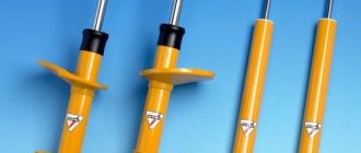
Selection of fog lights
The standard PTFs of the luxury Lada Vesta configuration are equipped with H16 lamps with a power of 19 watts, which cannot be called the optimal option. The fog lights listed in the table below have higher performance and, especially Valeo, have proven themselves when installed instead of standard ones.
In addition to headlights, you must purchase the following materials:
- 4-pin relay – 1;
- headlight on/off button - 1;
- protective corrugated cover (tubing) for wire - 5 m;
- wire - 5 m;
- 16 A fuse - 1.
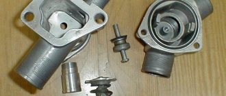
Preparing seats for the installation of PTF
By placing the bumper on the soft canvas with its front side, you gain access to the fastenings of the niche plugs in which the fog lights are installed.
The front bumper of the Lada Vesta Optima configuration is equipped with plugs that are not designed to attach PTF to them, and does not have any additional fasteners on the rear side.
In this case, it is necessary to purchase brackets for installing fog lights (2 pieces included - right and left).
If fasteners are present, they must be removed to get to the plugs.
After dismantling the PTF mounting brackets, remove the plugs held in the grooves by latches and self-tapping screws.
In the removed plastic plugs, using a drill with a core drill, holes are cut out with a diameter corresponding to the existing contour or selected headlights, after which the cut edge is processed with fine sandpaper and the parts are installed in their standard places.
Pinout of Lada Vesta: decoding of contact groups and equipment terminals
A complete set of car wiring is difficult to understand due to the abundance of connections and individual elements. For easier decoding, the wiring of the on-board equipment is presented below in individual parts.
Pinout of the front electrical harness
The front part of the wiring is 80% concentrated in the engine compartment and is responsible for the normal operation of the engine and the mechanisms that serve it. The following is the wiring sequence:
- 1/7 – contact group of the right and left headlights;
- 2/5 – “dads” of head optics foglights;
- 3 – alarm horn;
- 4 – standard electric fan serving the main engine radiator;
- 6 – audible warning signal;
- 8 – standard air conditioner pressure sensor;
- 9 – connection of the control unit for the central radiator head fan;
- 10 – junction of ECU transmission wiring;
- 11 – standard sensor that measures the air temperature outside the car;
- 12/13 – ABS system sensors that read the rotation speed of the front left and right wheels, respectively;
- 14 – ECU;
- 15 – engine compartment lid lock position controller;
- 16 – power supply to the electric drive of the windshield wiper;
- 17 – windshield washer motor;
- 18 – electrical part of the adsorber purge valve;
- 19 – main ABS module;
- 20 – output to block No. 3 of the standard terminal of the instrument panel;
- 21 – standard brake line expansion tank meter sensor;
- 22 – blocks for the mounting block of fuses and protective relays;
- 23 – output to block No. 2 of the instrument panel;
- 24 – standard power output of the heating element for the aft windshield;
- 25 – output to the first connector of the instrument cluster;
- 26 – terminal output for connecting the ECM unit.
Pinout of Lada Vesta, section responsible for starting the power plant
A small part of the wiring is responsible for the main elements of equipment designed to start the power plant:
- 1 – generator block;
- 2 – standard fuse module;
- 3 – connection of the power supply element for on-board circuits;
- 4 – electrical part of the starter;
- 5 – sending a signal to the wiring of the front harness.
Vesta devices pinout combinations
All groups of contacts coming from on-board systems and sensors are concentrated in this part. The area is responsible for indicating the vehicle's status in real time.
- 1-3/9 – output to the disconnect terminal of the front equipment harness;
- 4 – on the aft wire bundle;
- 5/19 – device of the steering column switch – left side;
- 6 – electrical socket, protective element;
- 7 – standard steering wheel rotation degree sensor;
- 8/14 – protective insert for the door window lift device;
- 10 – standard key for headlight adjustment;
- 11 – insert for protecting the main fuel pump;
- 12 – similar insert responsible for the heater fans;
- 13 – relay for the device of external lighting units of the car;
- 15 – standard PPS sensor;
- 16 – button for switching operating modes of the cargo compartment lock;
- 17 – diagnostic block, designed to connect the external scanner;
- 18 – arrangement of a combination of fusible protective inserts inside the passenger compartment;
- 20 – driver airbag output;
- 21 – standard control key module located on the steering wheel;
- 22 – contact group of the airbag ring;
- 23 – ignition lock cylinder;
- 24 – antenna of the standard immobilizer system;
- 25 – pins for connecting accelerator pedal contacts;
- 26 – stop signal button is turned off;
- 27 – electric power steering device;
- 28 – contact group of the heating system fan;
- 29 – dashboard;
- 30 – cigarette lighter;
- 31 – on-board audio player;
- 32 – emergency warning button;
- 33 – dashboard push-button switches;
- 34 – module for monitoring and starting the interior heating device;
- 35 – standard front passenger airbag;
- 36 – glove box illumination lamp;
- 37 – control device for the GLONASS satellite navigation system;
- 38 – secondary heater operation control module;
- 39 – airbag activation device switch;
- 40 – button for turning on the glove compartment lamp;
- 41 – central module for monitoring the electrical equipment of the cabin;
- 42 – antenna for standard satellite navigation of the GLONASS system;
- 43 – audio system receiver;
- 44 – signal and power supply output to the aft part of the right auxiliary instrument cluster;
- 45 – a similar waterproof output to the second connector of the above element.
Pinout of the rear additional wire bundle
- 1 – parking sensor control system;
- 2 – contact group for connecting the rear bumper lines;
- 3-4 – output to the central bundle of wires;
- 5 – electric drive for the cargo compartment lid lock;
- 6-7 – license plate lighting lamps;
- 8 – lamp designed to illuminate the interior space of the luggage compartment;
- 9 – auxiliary stop signal;
- 10 – directly the servo drive of the trunk lid lock;
- 11/12 – left side of the stern lights;
- 13 – heating of the wind window of the rear part of the vehicle;
- 14/15 – right side of the illumination of the rear optics module.
Pinout of the rear on-board wiring block
Here is the equipment located in the rear of the vehicle:
- 1 – terminal connector designed for connection with the left front door;
- 2/7 – ABS system sensor, responsible for the rear right/left wheel;
- 3/6 – door position switches;
- 4/5 – fuel pump control unit;
- 8/9 – connector to block No. 2/1 of the rear auxiliary harness;
- 10/11 – outputs for connecting to the dashboard;
- 12 – control unit for car body panel equipment;
- 13 – cabin module for measuring internal temperature;
- 14 – plug block on the driver’s door;
- 15 – precipitation warning module;
- 16 – device for lighting the interior of the car.
Rear bumper wiring diagram
A separate part of the power cables designed to supply power to equipment located in the aft bumper:
- 1/2/4/5 – parking sensors;
- 3 – stern fog lights;
- 6 – connection device to the rear auxiliary wiring bundle.
ECM wiring connection
- 1 – reverse signal lamp switch;
- 2 – standard DPKV;
- 3 – electric clutch of the air conditioning compressor;
- 4 – electronic engine control unit;
- 5 – DCC;
- 6 – electric throttle drive;
- 7 – DTOZH;
- 8 – diagnostic oxygen concentration sensor;
- 9 – sensor measuring absolute pressure in the intake manifold;
- 10 – output of a control device indicating a critical drop in pressure inside the crankcase compartment of the engine;
- 11 – electromagnetic insert for controlling the intake position;
- 12 – plug output to the front wiring harness;
- 13 – electric generator;
- 14 – detonation channel length sensor;
- 15/18 – blocks for connecting the ECM unit to the injectors, sequentially for each drive;
- 16 – phase distribution sensor;
- 17 – to the ignition coils;
- 19-22 – ignition elements;
- 23-26 – injector drivers;
- 27 – standard capacitor.
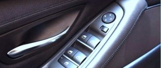
Driver's door pinout
- 1 – electrical part of the door lock servomotor;
- 2 – threshold illuminator lamp;
- 3 – electric window motor-reducer;
- 4 – device for connecting fuse links;
- 5 – drive for controlling the position of the rear view mirror;
- 6/7 – areas for connecting high-frequency/broadband speakers;
- 8 – output to the rear wiring harness.
Important! The pinout is also relevant for the passenger door.
Connecting the manual transmission electronics unit
There are only five nodes, each of which is responsible for its own part of the mechanism:
- clutch module actuator;
- gear selection device;
- sensor measuring the speed of the drive shaft;
- gear shift mechanism;
- exit to the EBKP connection.
Vesta radio pinout
The standard connection block for the radio has 12 pins corresponding to individual elements. Moreover, each wire is painted in its own color for identification.
| Color | Meaning |
| Red | Supply voltage to the radio |
| Blue | Antenna power |
| Yellow | Connecting power when ACC is turned on |
| Black | Weight control |
| Violet/violet with black stripe | Rear right speaker +/- |
| Grey/gray-black | Front right speaker +/- |
| White/White/Black | Left front emitter +/- |
| Green/black-green | Rear left speaker +/- |
The pinout of the standard Lada Vesta radio is relevant for devices of most modern analogues. Consequently, there are no problems when replacing it, which guarantees a large selection of third-party models for modifying the machine.
CAN bus pinout
There are several outputs here and each of them is responsible for its own section of the diagnostic device:
- 2 – positive terminal;
- 4 – grounding of body panels;
- 5 – signal ground wire;
- 6 – J2284;
- 7 – K-line diagnostics;
- 10 – tire 1850;
- 14 – CAN-LOW 2284;
- 15 – diagnostic line L;
- 16 – voltage supply from the car battery.
Connecting fog lights
The PTF power button is conveniently located on the central part of the console or to the left of the steering column in an existing recess. The hole for the button, depending on its configuration, is drilled or cut out, followed by careful processing of the edges without damaging the finish.
The wiring from both headlights should be brought into the cabin in the area of the pedal assembly; for this, it is convenient to route the wire of the right headlight along the transverse box between the side members.
To connect the headlights, it is advisable to use the classic circuit used in previous models of the Lada line (Priora, Kalina, Granta), simplified - take the power from the clamp bolt of the positive terminal of the battery.
This method will minimize interference with the vehicle’s electrical circuits and the cost of purchasing components.
How to avoid connection problems
When repairing or replacing electrical units, some users make mistakes by connecting the wrong terminals, which causes short circuits and burnout of parts. To avoid possible problems, experts recommend studying the location of pins and contact groups in advance, and also marking the contacts yourself before disconnecting them.
The above Lada Vesta pinout is taken from the manufacturer's service documentation supplied with the new car. At the same time, general provisions are indicated - depending on the configuration and year of manufacture, the connection of outputs and the location of units may differ slightly.
If you are unsure of your own abilities, it is recommended not to interfere with the car yourself, but to contact a qualified technician.
Hi all! Let me tell you, I allow car dealerships to use this article as instructions, just provide a link to this article.
Also, everything you do, you do at your own peril and risk. I do not recommend doing this yourself if you are not at all versed in electrical engineering.
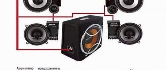
So, let's begin. We will need: DRLs themselves + turn signals
Connecting elements (chips)
Wires with a small cross-section. The length is at your discretion, for convenience I recommend approximately 50cm, 6 pcs. Before installation, I recommend disconnecting the battery.
Step 1: Remove the bumper. Instructions here: avtoskill.ru/remont-obslu…tsiya-s-foto-i-video.html Unscrew the chrome X's from the inside and carefully remove them. You can get it out without removing the bottom part of the chrome. You just need to tilt the top element to the side
In their place we install LED DRLs with turn signals. We pass the wires into the hole between the radiator grille and the bumper
We tighten it with standard self-tapping screws.
Step 2: Unscrew the DRL bulb. To do this, you need to turn it and take it out.
Step 3: Strip the wires to connect additional. equipment. IMPORTANT You can connect in 2 ways: 1) Connect to the green wire of the DRL - The LED strips will always light up when the dimensions are on. With high beam, with low beam - always. At night, the traffic police may have questions. However, your “bells and whistles” are always visible 2) Connect the DRL to the blue wire - The LED strips will light up only when the headlights and low beam modes are turned off. That is, only when the light knob is in the off position. The DRL will only operate during the day.
Having selected the wire, we cut the standard black protective insulation and strip the insulation of the wire (green or blue). I chose the option with the green wire.
We clean the place on the black wire. We unscrew the turn signal and clean the place on the yellow wire.
We strip the ends of the purchased wires, twist them onto the exposed areas of the cleaned wires, and carefully insulate them with electrical tape.
Step 4: Strip the opposite ends of the purchased wires. We put chips on the opposite end of the purchased wires and clamp them. We move the bumper closer and connect the LEDs to the chips in accordance with the diagram: DRL - black wire to the black wire of the LEDs. DRL green/blue wire - red LED wire Turn signals yellow wire - yellow LED wire.
At this point you can connect the battery and test.
I recommend insulating the chips too
Step 5: Put the bumper in place. Carefully, making sure that no wires are pinched and are located in front of the radiator, on the sides. Twist it and you're done!
Quite simple, right? :) But I’m sure it will come in handy for someone - the DRLs stopped lighting up, and the lights at the center console went out - the fuse for the DRLs is F18, in the block under the steering wheel. Change it to a new one and try again :)
Following up with a couple of photos:
If you have any questions, I will answer them all in the comments.
Tuning daytime running lights
On the Lada Vesta, the manufacturer uses double-filament lamps in the side lights and daytime running lights. If instead of them you install LEDs modified in a certain way, then the yellow color of these lights, which is ineffective during the day, will change to a brighter white with blue.
Before performing this operation, you need to familiarize yourself with the pinout of the Lada Vesta daytime running lights sockets, since on this sedan it is non-classical:
- on one side of the cartridge there should be a “-” in the form of two contacts or one common one;
- on the opposite side - “+” for side lights and “+” for daytime running lights.
When purchasing LEDs, you must ensure that the polarity of the lamp base and the Vesta socket match. If such LEDs could not be found, a way out, which is not always harmless, may be to bend the contact pins of the elements according to the indicated pattern.
This procedure may result not only in the failure of the fuse, but also in damage to the vehicle’s electronic components, which can lead to a complete loss of the right to warranty service.
The desire to make your car better is familiar and understandable to any motorist. However, when deciding to carry out tuning on your own or even with the help of professionals, but before the expiration of the warranty period, you should carefully weigh the feasibility of performing this work and the consequences that are often inevitable with unqualified intervention.
Source
Side turn signal lamp
W5W side turn signal lamp design:
Designation of the side turn signal lamp according to ECE - W5W
Technical characteristics of the side turn signal lamp W5W Vesta frets:
- Power - 5 W;
- Incandescent lamp;
- The lamp base is glass;
- Filament - 1 pc;
- The color of the flask is colorless;
Dimensions of the side turn signal lamp W5W Vesta frets:
- The diameter of the flask is 10.3 mm;
- Lamp height - 26.8 mm;
- Base width - 9.5 mm;