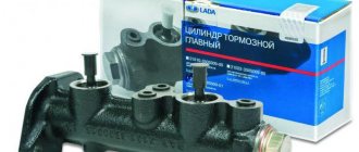
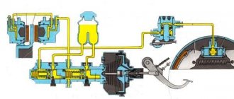
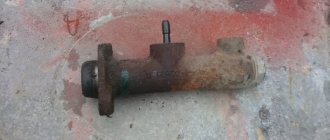
Replacing the main brake cylinder of a VAZ 2121
1. Disconnect the flexible hoses from the master cylinder and close the hose openings and fittings on the cylinder to prevent fluid from leaking from the reservoir and preventing dust, dirt or foreign matter from entering the cylinder. 2. Disconnect the steel pipes from the master cylinder that drain fluid to the wheel cylinders of the front and rear brakes, having first unscrewed the pipe nuts. 3. Remove the cylinder by unscrewing the nuts securing it to the vacuum booster. 4. Install the master cylinder in the reverse order of removal. After installing the cylinder, bleed the hydraulic drive system to remove air from it.
Disassembly and assembly
1. Remove fittings 2 with connecting sleeves 3, unscrew locking bolts 5 and remove all parts in the order shown in Fig. Master cylinder parts. 2. Assemble the cylinder in the reverse order of disassembly. In this case, lubricate the parts with brake fluid. When assembling, use tool 67.7853.9543.
Before assembly, wash all parts with isopropyl alcohol; Dry them with a blast of compressed air or wipe them with a clean cloth, avoiding contact with mineral oil, kerosene or diesel fuel, which can damage the seals.
Warning The time for washing the sealing rings in isopropyl alcohol is no more than 20 s, followed by blowing with compressed air.
The cylinder bore and the working surface of the pistons must be completely clean, free of rust, marks and other defects. An increased gap between the cylinder and pistons is unacceptable.
Each time you disassemble the cylinder, replace the seals with new ones, even if they appear to be in good condition.
Check the elasticity of the piston spring, the length of which should be 41.7 mm under a load of 42.18 ± 3.92 N (4.3 ± 0.4 kgf), 21 mm under a load of 90.64 ± 8.83 N (9.24 ±0.9 kgf), in a free state - 59.7 mm.
Master cylinder leak test diagram
| 1 – valve for pumping the stand; 2 – pressure gauge; 3 – absorbing cylinder; 4 – main cylinder; 5 – flywheel; 6 – pusher displacement indicator; 7 – tap; 8 – vessel |
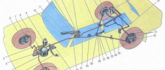
Repair work and restoration of effective performance of rear brakes
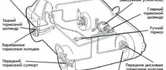
The Niva's braking system is quite tense. The weight of the car compared to the VAZ-2106 increased by a quarter of a ton, or almost 28%. The rear brake mechanisms have not undergone any changes. But the larger diameter of the brake disc on the front axle provides the Niva with acceptable braking performance (Table 1).
As you can see, the Niva is only slightly inferior to the “classic” and front-wheel drive vehicles; the braking distance has increased by only 5%. Please note that Samara failed to reduce the braking distance, despite its significantly lower gross weight. Experts agree that Samara's braking system, to put it mildly, is not very successful. Niva is a different matter. For a jeep with a gross weight of about 1,700 kg, a five percent loss in braking performance compared to a passenger sedan is a remarkable result.
* Braking distance with full load from a speed of 80 km/h.
However, these brakes require increased attention and care. .Factory front pads do not last more than 15 thousand km. Replacing with products from specialized companies allows you to extend the service life up to 25..28 thousand km. This is with a conditionally balanced driving style. Three-cylinder brake calipers can be capricious if you do not keep the boots clean. It is especially important to clean the brakes from dirt if you frequently go off-road.
Today we'll tackle the rear brakes. It would seem that due to the low load on them and the simple design, these brake mechanisms do not deserve the cost of preventive inspections. However, supporters of this position inevitably pay for their frivolity with a general decrease in the effectiveness of the braking system, loss of the feeling of control of the car, and sometimes cash for repairing rammed cars. The most likely problems are summarized in table. 2. Other faults, such as loose tension springs or excessive wear on the drums, are quite rare and cannot be called typical.
Let's look at troubleshooting using a specific example.
Car: Niva BA3-21213, cherry color.
Age: Operated year-round and daily since March 1997, mileage 205,045 km
Symptoms: Reduced brake efficiency, slight sagging of the brake pedal, noise from the right rear wheel.
Workplace: According to established tradition, we carry out work where the car that is used daily is stored - in the fresh air. On the day determined for repairs, the air was not only fresh, but also frosty - approximately minus 12°C.
We pay special attention to the procedure for lifting and securing the machine. This is especially important for today's renovations. During the work, significant efforts will have to be made along the longitudinal axis of the car. And given the time of year and the corresponding surface under the car - uneven compacted snow and lumpy ice - we do not recommend relying on a standard rack and pinion jack. Small hydraulic jacks for 2-5 tons will not add confidence either - they have a small area of support on the ground and a very miniature thrust bearing with an area about the size of a 5-ruble coin at most. To lift the car, we strongly recommend using a rolling jack with a lifting capacity of 2, or better, 3 tons, and powerful, always steel, support stands with profiled (not flat) thrust bearings. Our colleagues from the editors of the magazine “Toys for Big People” were sympathetic to the idea of do-it-yourself repairs outside the garage and offered a 3-ton rolling jack with a variable swing plane of the drive handle and folding (!) supports for 6 tons (see photo 1).
Table 2. Main malfunctions of Niva rear brakes
| |||||||||||
Malfunction
|
Time spent on repairs -1.5 hours
Tools and equipment : Cross wheel wrench, slotted screwdriver (2 pcs), pliers, hammer (600-800 g), a piece of wire or thick wire 50 cm long, a wooden block, keys “8”, “10”, "at 13".
Sequence of work:
1. Loosen the wheel nuts (photo 1).
2. We raise the car by placing a jack under the rear axle gear housing (photo 2).
3. We install a support under one of the sides of the beam.
4. We remove the jack and bring it under the opposite side. We select a lifting height that is convenient for work.
5. We remove the wheel. It is convenient to use as a stool.
6. Using a 12mm wrench, unscrew the two brake drum mounting bolts. Some Niva owners even install these bolts. We consider this decision justified, since the screwed-on wheel ensures case fixation of the drum.
7. Tapping the drum around the circumference from the inside with a hammer through a wooden block, carefully knock it down.
8. We make a diagnosis.
The picture that opens (photo 3) allows you to immediately determine the cause of the malfunction and cull the faulty parts:
a) First of all, this is a cylinder that works in one direction. The second side piston is rusty. This is fault number 3 in our table. The cylinder needs to be replaced.
b) The cause of the noise is the lost “soldier” of the fastening of one of the blocks. Malfunction No. 4. We are preparing new fasteners.
c) The front brake pad is severely worn. The reason is a faulty cylinder. Malfunction No. 1. Changing the block
From our practice: if the pads wear unevenly, there is no need to follow the operating instructions and change the entire set. It is enough to replace the worn pad. This will not cause any uneven braking. The same applies to the front brakes.
8. Remove the upper spring using one of the 6-7 methods indicated in the photo. If this is your first time performing this operation, we advise you not to neglect safety glasses.
9. Remove the spacer bar. Using pliers, turn the “somatic” rod (photo 10), remove its cup and remove the “soldier”. Remove the worn brake pad.
10. Using a “10” wrench (or a special wrench that ensures reliable fixation of the unscrewed hexagon), unscrew the brake pipe fitting on the cylinder (photo 5). It is useful to first clean the fitting and the heads of the cylinder mounting bolts from dirt, use an aerosol like WD-40 and a good tool.
Attention! If you work inaccurately, there is a high probability of damaging the edges of the fitting without unscrewing it from the cylinder. In this case, you are faced with replacing the brake pipe.
11. Using a 10mm wrench, unscrew the cylinder mounting bolts.
12. Using a powerful screwdriver, disconnect the faulty cylinder from the brake shield (photo 9).
13. We are preparing a new cylinder (photo 8). We lubricate the threads in the holes for the bolts, remove the protective plug, and then install it on the brake shield (photo 11). We tighten the fastening bolts (wrench “10”), fasten the brake pipe (wrench “10”, photo 12).
14. We install a new block, starting it from the bottom (photo 13) and the lower spring.
15. Holding the block, we install a new “soldier”. We insert the rod from the back of the brake shield, through the block (photo 14), attach the cup and spring using pliers (photo 15).
16. Install the spacer bar and the upper tension spring. This operation often causes difficulties. The spring breaks, falls, etc. We recommend a method that guarantees success. True, it will be possible to implement it without difficulty, first of all, by those who fulfilled the norms at school (TO 1 for a silver badge.
A strong aluminum or copper wire with a diameter of 2-3 mm is threaded into the hook of the spring, which must be inserted into the hole of the free block. Grasping the wire with your right hand, vigorously stretch the spring, and with the thumb of your left hand, guide the hook into the hole in the block (photo 16). If you cannot stretch the spring to the desired length on your own, ask a friend to help. Holding the wire with both hands, he will stretch the spring, and you will insert its end into the hole.
17. Install the brake drum. Before installation, do not forget to lubricate its surfaces in contact with the hub with grease. This simple procedure will prevent it from “souring” and will make it easier to remove the drum during the next repair.
18. We bleed the brake system according to the repair instructions. As a rule, you can limit yourself to only the installed cylinder.
18. We install the wheel, remove the Niva from the supports and jack.
Video
Source
GTZ NIVA
Removing and installing the Niva brake master cylinder (instructions)
Remove the spare wheel support bracket for the VAZ 2131.
Using pliers, loosen the clamps securing the flexible hoses to the fittings of the master brake cylinder.
Carefully holding the fittings, remove the hoses. Drain the brake fluid from the reservoir into a substitute container. To replace the brake master cylinder fitting...
and remove it from the brake master cylinder socket.
Use a screwdriver to pry up the rubber connecting sleeve...
and take it out. To remove a vehicle's brake master cylinder...
Using a special “10” wrench covering the five sides of the nut, unscrew the fittings of the four Niva 2121 brake pipes.
We remove the pipes from the brake cylinder Niva 2131.
Using a 17mm spanner, unscrew the two nuts securing the master brake cylinder to the vacuum booster...
and remove the main brake cylinder of the VAZ 2121. Install the main brake cylinder of the VAZ 2121 in the reverse order. We bleed the hydraulic drive system.
Repair of GTZ NIVA
Problem: the Main Brake Cylinder on the NIVA leaked directly into the Vacuum Booster.
I took out the main brake assembly with vacuum from a Peugeot 405 from old bins, and also bought two cylinder connectors for the front calipers and two front brake hoses from Shevik.
cylinder connector VAZ-2123
front brake hose VAZ-2123
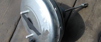
GTZ and VUT from Peugeot 405 (front view)
GTZ and VUT from Peugeot 405 (rear view)
I started disassembling the old system. As it turned out, the old owner was wise here too. I threw out absolutely everything old, leaving only the pedal and the front cylinders, and began to assemble everything in a new way: 1. Put the cylinder connectors on the front calipers;
installed cylinder connector on brake cylinder
installed cylinder connector on brake cylinder
2. At first I took the hoses to the turners - they cut threads on the outside at the ends where the tube is screwed in, turned out two thin nuts and two thin washers - to attach one end of the hose to the body;
here we modify the brake hoses
3. Installed the hoses, connecting them at one end with the cylinder connectors, and securing the other end with the modified end to the body in the normal place; 4.Laid new copper pipes from the tee to the hoses. Then it came to the Chief with the vacuum cleaner. Having estimated approximately where it would stand, I began to split hairs: 1. Making an adapter bracket, because the vacuum itself is much larger than Nivovsky, we had to carry it some distance
plate for vacuum booster
We weld the plates together with an angle of 25x25mm and a length of 120mm at 4 corners; 2. Manufacturing of an intermediate drive rod from the pedal to the vacuum itself with the possibility of adjusting its length;
transitional drive rod from pedal to amplifier with adjustable length
3. Because The main brake reservoir in Peugeot is not installed as it should be, we had to make adapters to connect the hoses from the fluid reservoir and lengthen the hoses themselves. Once all of this was done, the adapter bracket was painted and dried, and assembly began. Everything fell into place, as I had planned. All that remained was to run the pipelines from the main cylinder to the tees. It was then that I decided to check the vacuum cylinder that had been lying in the garage for about ten years - I plugged the outlet holes of the cylinder and tried to bleed it. To my surprise, everything turned out to be more than 100% working. Next, I ran the pipelines to the tees, only on the tee that placed one plug on the rear brakes. After all, now the brakes are like those of a normal car - rear/front.
plug on tee for rear brakes
We started bleeding the system - not an easy task, because there were still two bleeding fittings left on the front cylinders. But we still succeeded. I took it for a test drive and was more than pleased. The brakes are 100% clearer. Even when skidding, the car goes smoothly - without skidding, all wheels brake as they should, and not each on its own. The result exceeded my expectations. And under the hood it all looks like this.
everything is in place and looks like this
Video on GTZ repair - replacing cuffs
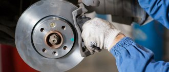
Replacing brake discs and pads NIVA
Contents of the article: Replacing Niva brake discs and pads (step-by-step instructions) Video on replacing brakes
What do the numbers in the Niva index mean?
To understand the features of the wiring and electrical equipment of a Niva 2131 car or another model with an injector or carburetor, let’s look at the index designations:
- VAZ 21213 - this is how a Niva with a carburetor is designated. In this case, the engine volume is 1.7 liters.
- VAZ 21214 is the same carburetor with the same engine size. Only in this case the car is characterized by a distributed fuel injection system.
- VAZ 21213 is also a carburetor, only Niva with such digital designations can have a 1.8-liter engine.
- VAZ 21073. This Niva can be equipped with either a Solex carburetor or an injector. The ignition system in these cars is contactless.
- As for the Niva 21215 models, this index designates export versions of vehicles equipped with a diesel engine from the manufacturer Citroen.
Officially, Niva vehicles equipped with diesel engines have never been sold in the Russian Federation and the countries of the former USSR. The cost of such a vehicle, of course, was higher. Those fans of domestic SUVs who were willing to pay such a price could only purchase a car abroad.
Below is a diagram of the VAZ 2121. If you are interested in the electrical diagram of another model, for example, 2131, then it will have certain differences from this modification. For example, in the case of a carburetor, the electrical circuit for charging the battery and ignition system is not protected, unlike injectors.
Generator wiring diagram 2121
Connection diagram for starter car Niva 21214 injector
Starters 21070-3708010-01, 21214-3708010-01, 5722.3708 and their analogues from different manufacturers can be installed on a Niva 21214 car with a 21214 1.7 liter injection engine.
Here is a diagram of their connection (they are all connected in the same way) with a description of the operating procedure (turning on and off).
Connection diagram for a starter on a Niva 21214 injector car
Description of the starter connection diagram
— The voltage in the electrical circuit for turning on the starter is supplied to the positive terminal of the battery through terminal “30” of the generator.
— The starter is turned on by turning the key in the ignition switch to position II (starter). In this case, voltage is supplied to terminal “D” of the starter retractor (traction) relay. The relay armature is pulled into the interior of the pull-in relay (the pull-in winding of the relay is activated), and the bendix associated with it moves forward. Its gear meshes with the teeth of the flywheel. The contacts inside the relay close and electric current from the battery is supplied to the starter motor, turning it along with the gear and flywheel. The engine starts.
After the key in the ignition switch returns to position I, the holding winding of the relay is de-energized, and the armature inside it returns to its original position under the action of the spring. The contacts inside the relay are disconnected, the starter is de-energized and stops.
— Power is supplied to the coils of the retractor relay through the starter interlock relay mounted on the mounting stud of the master cylinder reservoir. Controls the operation of the ECU (control unit) relay. It turns on the locking relay when the key is turned in the ignition switch and allows you to start the car engine and turns it off when it detects that the engine is idling, protects the starter from turning on while the engine is running.