Hello, we would like to introduce the idea of making a powerful compressor for the garage. This compressor was built 7 years ago, it is quite powerful, moderately quiet, and does not require maintenance.
The choice of a car engine was mainly due to the fact that its operation is more stable than that of an electric motor, easier, and reliable starting even at high pressure. The availability and price of spare parts was also important.
The engine was purchased at a dismantling station, new liners and rings were installed. The pistons were machined so that the bottoms were completely flat. The oil supply channel for head lubrication has been improved. The heads are used from the tractor compressor - 3 pieces, they are cut to match each other and the plane of the block.
For the heads there was a suction manifold made from a pipe and an air filter with a housing was installed at the end, which largely muffles the operating noise. A 1″ check valve is installed in the cylinder at the entrance; between the compressor and the tubes there is a fan from the refrigeration machine; it turns on together with the compressor motor.
The compressor drives a 2.2 kW 1450 rpm motor via 2 V-belts, controlled by a single-phase wire through a pressure switch.
Pressure tests were done up to 14 bar (they didn’t risk it anymore), the system did not overheat. Currently working in a car workshop, the pressure switches from 6 bar to 10 bar. During the entire period of operation there were no problems with it, only once were the belts tightened and the filter replaced. In general, we hope someone likes this idea.
I have already written about the compressor that I use for car repairs, but this compressor is, after all, suitable for painting, but cannot cope with my growing requirements. In particular, I needed a compressor to work with an orbital sander. I found a way out, or rather not so much a way out as probably a field for experimentation :)
Do-it-yourself compressor from an internal combustion engine
I already wrote about the compressor that I use to paint cars, but as it turned out, this compressor is not suitable for working with a pneumatic orbital machine. The Chinese compressor cannot cope with the air flow of the orbital machine; a receiver fully inflated to 8 atmospheres is enough for 1 - 1.5 minutes of operation of the machine, or even less. Not in order.
I read on Stardrive about an internal combustion engine compressor, the guys there used a VAZ engine, the performance was around 1000 l/min. It’s good, but I don’t have anywhere to put it yet, and it’s not that easy to make. Another option came to my mind, to use an engine that was previously used to drive various agricultural equipment (machines, etc.) - its marking is ZID 4.5. Another important aspect in favor of this internal combustion engine is lubrication - oil is poured into the sump and circulates in the engine, and the cooling is also quite good - when running for about 1 hour, the compressor is slightly warm.
If I’m not mistaken, then its working volume is 500 cm3, which is quite a lot, only slightly less than in the SO-7 compressor. This engine is a four-stroke, so there are valves. Those who know how a 4-stroke engine works will understand that when using the engine as a compressor, the useful power stroke (air injection) is one for two crankshaft revolutions. This is when using the conventional gas distribution system of the ZID engine, I used this one. This leads to a decrease in performance, but for my purposes the compressor was quite suitable.
How to make a compressor from an internal combustion engine?
- To begin with, we need to drive this motor, for this I used a 4 kW electric motor, although it was possible to take 3 kW, naturally 380 V. I think it is possible to drive such a compressor from 220 V, but you need to play with the pulleys and you will not get such performance as on 380. The pulley on the compressor was original, the one on the engine was a little larger, the speed on the compressor shaft was about 1300 rpm.
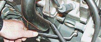
- Each compressor is equipped with a check valve; this valve makes it possible to push out a volume of air during the working stroke of the piston and not return back into the cylinder. When making homemade compressors, this is one of the biggest problems, finding and adapting. I found a solution, perhaps not ideal, but quite simple and does not require turning work, and without interfering with the design of the engine, it can be easily returned to normal operating mode.
Do-it-yourself drive supercharger for a VAZ
One of the possibilities to extend the life of an old car, for example any VAZ 2107, 2106, 2114, 2112, is its tuning. Of course, in this case we are not talking about installing new wheels and covers, but primarily about increasing engine power. And one of the simplest and most affordable options for ensuring this is to install a mechanical supercharger on the motor yourself.
Mechanical supercharger for VAZ - pros and cons
The larger the engine and the more cylinders it has, the higher its power. This is the very first conclusion when observing motors and machines. But this is not always the case. The more fuel burned in the engine cylinders, the more power it can produce.
But the cylinder volume is finite, and I want to have increased power. This is where a mechanical air blower comes to the rescue. The principle of its operation is extremely simple and works on any car, including the VAZ 2107, 2106, 2114, 2112 family - it supplies additional air to the engine, resulting in:
- the purging of the cylinders increases, and they are better freed from the remains of burnt fuel; more fuel enters the engine cylinders, which ensures more power; the compression ratio increases, which also gives an increase in power.
electric turbo supercharging
This approach is almost similar to the turbo mode used on diesel engines. Only there, for these purposes, a turbocharger is used, driven by exhaust gases, and in this case, a mechanical air blower, which is connected to the engine crankshaft by a belt. This approach is much simpler, the air supply depends on the engine speed, the higher it is, the more air is supplied; and also does not require ensuring the operating modes of the turbine and can be done with your own hands on any VAZ car.
It is worth considering that if a mechanical supercharger is installed on a VAZ injection car, then a firmware change will be required. However, a similar modification can be made for a carburetor car, only in this case, most likely, you will have to change the jets in the carburetor and adjust the ignition timing.
Do not forget that you are boosting a VAZ engine, be it any of its models 2107, 2106, 2114, 2112, the work must be carried out comprehensively, and only then is it possible to obtain the expected result. However, this is not such a big price to pay for the increase in power.
How to install an air blower yourself
There are several approaches that allow you to install a mechanical air blower on VAZ family cars with your own hands. This means making a device yourself that provides turbo mode or boosting the engine, or using a ready-made KIT kit.
Homemade supercharger for VAZ
With this approach, the mechanical air blower will be decisive. The entire future design depends on it. The main thing is to find an air supercharger from an imported car that meets the requirements, or you will have to use a homemade one.
This is also possible, and in this case suitable parts and components from completely unexpected devices, for example, a vacuum cleaner, are used. When making such a homemade air blower, you need to take literally everything into account - dimensions, weight, placement in the engine compartment, how and where the drive pulley will be located and belt, the performance of this device, operating modes (short-term or long-term), lubrication capabilities and much, much more. Once the compressor becomes clear, it is necessary to calculate the implementation of the turbo mode for the engine.
Here it is necessary to take into account how the fuel and cooling system of the car will be changed, what changes need to be made to its control and how to do this, what pressure will be acceptable for safe operation of the engine when implementing a turbo mode using such a device.
Even the far from complete list of questions shown shows that making a homemade air supercharger for a VAZ of any family, be it 2107, 2106, 2114, 2112, is quite difficult, but possible. An example would be a photo showing that such work has been successfully completed. True, this is not a VAZ, but the fact itself is important - it is possible to make a homemade air compressor in which its drive unit is connected to the engine crankshaft.
Do-it-yourself drive supercharger - from a KIT kit
Yes, there are such kits on sale that allow you to implement the turbo mode in VAZ 2107, 2106, 2114, 2112 cars with your own hands. As a rule, it includes everything needed to assemble and install such a device on a car - the compressor itself, belts, drive unit , brackets and air ducts. What such a kit is like can be seen in the photo below.
The main advantage of this approach to implementing the turbo mode on your car is the simplicity and complete adaptation of technical solutions to a specific option - 2107, 2106, 2114, 2112. As a rule, the manufacturers of kit kits are Chinese manufacturers, which ensures their fairly reasonable price.
As an advantage of implementing the turbo mode in this way, it is worth noting that it is tailored specifically to VAZ cars of one model or another (2107, 2106, 2114, 2112). The advantages of this approach also include the fact that under certain conditions, when the level of additional pressure created is not more than half a bar, no intervention is required in the vehicle’s fuel system. It is not practical to describe the procedure for implementing the turbo mode from such a set; each of them has its own instructions for assembly.
The disadvantages include the country of origin, but it depends on your luck. The video will additionally help you understand what the car looks like after modification and how to carry it out. One of the ways available to car enthusiasts to boost the engine of an old car and give it a new life is to install an air supercharger. You can do this work yourself if you use commercially available KIT kits for VAZ cars.
How do you rate the article?
Air compressor made from refrigerator and fire extinguisher parts
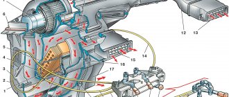
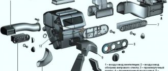
This unit operates almost silently. Let's look at the diagram of the future design and make a list of the necessary components and parts.
1 — tube for filling oil; 2 - starting relay; 3 - compressor; 4 - copper tubes; 5 — hoses; 6 — diesel filter; 7 — gasoline filter; 8 — air inlet; 9 — pressure switch; 10 — crosspiece; 11 - safety valve; 12 - tee; 13 — receiver from a fire extinguisher; 14 — pressure reducer with pressure gauge; 15 — moisture-oil trap; 16 — pneumatic socket
Necessary parts, materials and tools
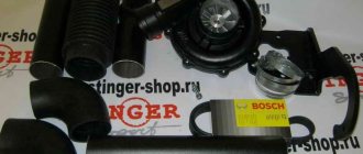
The main elements taken are: a motor-compressor from a refrigerator (preferably made in the USSR) and a fire extinguisher cylinder, which will be used as a receiver. If they are not available, then you can look for a compressor from a non-working refrigerator at repair shops or at metal collection points. A fire extinguisher can be purchased on the secondary market or you can involve friends in the search, who at work may have written off fire extinguisher, fire extinguisher, fire extinguisher for 10 liters. The fire extinguisher cylinder must be emptied safely.
In addition you will need:
- pressure gauge (as for a pump, water heater);
- diesel filter;
- filter for a gasoline engine;
- pressure switch;
- electric toggle switch;
- pressure regulator (reducer) with pressure gauge;
- reinforced hose;
- water pipes, tees, adapters, fittings + clamps, hardware;
- materials for creating a frame - metal or wood + furniture wheels;
- safety valve (to relieve excess pressure);
- self-closing air inlet (for connection, for example, to an airbrush).
In addition, you will need tools: a hacksaw, a wrench, a syringe, as well as FUM-leta, anti-rust, synthetic motor oil, paint or enamel for metal.
Assembly steps
Before starting assembly, you need to prepare the motor-compressor and fire extinguisher cylinder.
Preparing the motor-compressor
Three tubes come out of the motor-compressor, two of which are open (air inlet and outlet), and the third, with a sealed end, is for changing the oil. To find the air inlet and outlet, you need to briefly apply current to the compressor and put the appropriate marks on the tubes.
Next, you need to carefully file or cut off the sealed end, making sure that no copper filings get inside the tube. Then drain the oil inside and use a syringe to fill in motor, synthetic or semi-synthetic. You can seal the tube by selecting a screw of a suitable diameter, which must be wrapped with FUM tape and screwed into the hole. Sealant can be applied over the joint. If necessary, paint the surface with enamel.
Preparing the receiver
You need to remove the shut-off valve (SPV) from the empty fire extinguisher cylinder. Clean the outside of the container from rust and dirt, and pour “anti-rust” inside and hold it for as long as indicated on the product label. Let it dry and screw on the lid with the hole from the ZPK. We screw the adapter into the hole (if necessary) and attach the cross.
We attach a pressure switch to the upper branch pipe, on one side we screw in a tee and connect a pressure gauge, on the other we mount a safety valve or a valve for bleeding air manually (optional). Where required, we use adapters. If necessary, we paint the balloon.
Auto compressor modernization
You can make a mini compressor for connecting a spray gun or airbrush from a car pump, improving it a little. Modernizing the compressor will increase its power (performance) and will consist of adapting it to a voltage of 220 V (instead of 12 V), connecting the device to the receiver and installing automation.
Adaptation of the device to 220 V voltage
To connect the car pump to a 220 V network, you will need to find some kind of power supply unit (PSU), the output of which will be 12 V and the current strength suitable for the device.
You can find out the current consumed by the device by looking at its nameplate. In this case, the power supply from the PC (see figure above) will be quite sufficient in terms of current and voltage.
So, if you plug the electrical cord into your PC's power supply and turn it on, nothing will happen. This is explained by the fact that the power supply will not turn on until it receives a signal from the PC. To simulate turning on a PC, you need to insert a jumper on the connector coming out of the power supply. You will need to find among the many conductors one wire that is green and the other wire that is black, as shown in the following photo.
These wires can be cut and twisted, but it is better to short them with a jumper.
Next, you need to find 2 more wires at the output of the power supply: one yellow, this will be “+”, and one black with the polarity “-”. You can take any wires of these colors from any bundle of conductors.
Since the car pump has a plug for connecting to the car’s cigarette lighter, you can cut it off and connect the device with the corresponding color wires from the power supply.
But it will be better if you buy a car cigarette lighter and connect it to the power supply, and connect the device itself using a standard plug.
There are 3 wires coming out of the cigarette lighter: red – “+”, black – “-” and yellow – “+”, intended for connecting the LED. Connect the conductors to the cigarette lighter, observing the polarity (see photo below).
If you insert the plug from the device into the cigarette lighter, you will get a 220 V electric air compressor, capable of not only inflating tires, but also working with an airbrush.
Connecting additional elements
To connect the device to the receiver, you need to assemble the structure shown in the diagram below.
This harness includes the following elements.
- Crosspiece having all outputs with BP1/2. The marking means: “BP” - internal thread, “1/2” - thread diameter in inches.
- The tee has all outlets with HP1/2 (“HP” - external thread).
- Valves in the amount of 2 pcs. (BP1/2 – BP1/2). Designed to block air movement in both directions. Double marking means that there is an internal thread on both sides of the valve.
- Check valve. Designed to allow air to flow in one direction only. You can install a simple spring valve BP1/2 - BP1/2. If you plan to work with a pressure of 6-7 bar, then it is necessary to select a check valve that does not have plastic parts.
- A straight nipple is an adapter with 2 external threads (HP1/2).
- Transition nipple HP1/2 – HP1/4. Allows you to change from one external thread diameter to another.
- Extension (60 mm) HP1/2 – HP1/2. This is the same nipple, only straight. That is, the thread at both ends has the same diameter.
- Transitional coupling. It is an adapter from an internal thread of one diameter to an internal thread of another. In this case, from BP1/2 to BP1/8.
- A tee having all outlets already with HP1/8 thread.
- Direct coupling VR1/8 – VR1/8. Has 2 identical internal threads.
- Adapter for HP1/8 hose.
- Pressure regulator (pressostat) with moisture-oil separator. The pressure switch allows you to maintain the air pressure in the receiver not lower than the minimum and not higher than the maximum permissible level. A moisture separator may not be installed if the unit will be used as a tire inflator. When using the unit for painting, installing a moisture-oil separator is a must.
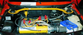
Air compressor made from auto parts
The air compressor has a fundamentally different design, which is assembled on the basis of a ZIL compressor and a separate engine. This is more powerful equipment that can also be used to connect pneumatic tools. Very noisy unit.
Layout drawing of the compressor unit: 1 - compressor from ZIL-130; 2 — frame from a corner; 3 - safety valve; 4 - standard pressure gauge; 5 — transfer case; 6 - three-phase electric motor (1 kW, 1380 rpm); 7 — start box (from the washing machine); 8 - capacitor bank (working capacity - 25–30 μF, starting capacity - 70–100 μF); 9 — receiver (from an oxygen cylinder or KrAZ muffler); 10 — V-belt transmission (reduction 1:3); 11 — “Stop” button; 12 — “Engine start” button; 13 - button for short-term activation of the starting capacitor battery; 14 — fitting of the flow (outlet) valve; 15 — aluminum tubes Ø 6 mm; 16 — exhaust valves; 17 — intake valves; 18 — wheels (4 pcs.); 19 — transverse stiffener; 20 — tie rod (M10 — 4 pcs.); 21 - drain hole with plug
Connecting a three-phase motor to a single-phase network: a - “triangle”; b - “star”
You can see an example of self-assembly of an air compress from new parts and components in the video.
Recent comments
- admin to the post differences between 8v and 16v controllers using the example of January 7.2 8v and Bosch 7.9.7 16v
- admin to post Useful information
- admin to post Atomic soft
- admin to the post Answered questions (comments) over the past months
- admin to the entry Pinout of the connection block SUD M7.9.7./January7.2 to the interior wiring of the Europanel (VAZ 2114)
- admin to the entry Chiptuning - About the table of monitoring stations and control centers (for dummies)
- admin to the post Answer to a question about Atomic Tune 2.8.8
- daser on Angel Eyes
- Kirill on the entry Pinout of the connection block SUD M7.9.7./January7.2 to the interior wiring of the Europanel (VAZ 2114)
- Anonymous to the post Answered questions (comments) in recent months
Compressor machine
Choosing the best compressor for painting
Compressor machines are widely used in leading sectors of the national economy - ferrous metallurgy, chemical, gas, oil and petrochemical industries. By their purpose, compressors are technological machines. They move and compress various gaseous media and participate in a variety of technological processes. The main requirement made by consumers of compressor machines is their high reliability and trouble-free operation over a long period of operation.
Compressor machines, in which instead of a piston the pressure on the metal is produced by compressed air, are divided into machines with a hot compression chamber and with a cold compression chamber.
Compressor machines (with a hot pressure chamber) are semi-automatic and automatic. They are equipped with fuses that prevent air from entering the chamber when the molds are not completely closed or when the mouthpiece does not fit tightly to the sprue bushing. There are different machines with a closed and open bathroom.
A compressor machine for casting easily oxidized alloys (magnesium, etc.) has a stationary gooseneck immersed in a bath. It works on the principle of compressor machines, with the only difference being that the gooseneck is filled through a special hole located in the lower part. The metal bath is located under a neutral gas environment; The same gas produces pressure on the metal.
Compressor machines are named according to their purpose and discharge pressure range.
| Diagrams of injection molding machines. |
Compressor machines always have a hot compression chamber and they can be divided into compressor machines and machines with adjustable or low pressure.
Compressor machines (compressors) are designed to move and compress gases. Based on their operating principle, they are divided into volumetric and dynamic compression machines. Volumetric compression machines are in turn divided into horizontal piston (one-way, opposed, angular), vertical piston, rotary with rolled profiles (screw and rute type), plate rotary and liquid-ring rotary. Dynamic compressors (turbocompressors) are divided into centrifugal, axial and diatomal.
Based on the principle of energy conversion, compressor machines can be divided into gas-dynamic and volumetric.
Compressor machines must ensure a constant weight quantity of supplied air in relation to the established operating mode of the consumer. With changing initial conditions at the suction, compressor machines can provide this if throttling is introduced at the suction.
Compressor machines are also divided according to their performance. Productivity refers to the amount of gas supplied by the compressor to the consumer per unit of time. If productivity is expressed in units of volume per time, then the volume is determined based on the gas parameters in front of the compressor suction pipe. The productivity expressed in this way is called reduced, and the amount of gas supplied during one stroke of the piston is called feed. According to the given performance, piston compressors are divided into the following groups.
Compressor machines designed for long-term continuous operation have a less stressful mode, so for them they take Pt closer to three and select lower crankshaft speeds.
| Polytropic compression processes in the L, 5-diagram. |
The compressor machine is an open thermodynamic system. The theory of compressor machines, which has practically acceptable accuracy, is based on the thermodynamics of an ideal gas.
Compressor machines that provide an increase in pressure by a small amount (up to OD MPa) are called blowers or gas blowers.
General information
The process of air compression in the engine occurs in the inlet device and in the compressor. At subsonic flight speeds, air compression in the engine is carried out mainly by the compressor. With the transition to supersonic flight speeds, it becomes possible to significantly increase the air pressure in the inlet device due to the high-speed pressure.
Subsonic input devices are used for flights at subsonic and low supersonic speeds (M = 1.3...1.5), at which energy losses in a direct shock wave are still insignificant.
One of the main parameters characterizing the efficiency of inlet devices is the total pressure conservation coefficient:
σ*in=RR**inH ,
where P*in is the total pressure behind the inlet device; Р*Н - total pressure of the free flow.
He evaluates the gas-dynamic perfection of the inlet device. The inlet device of the side engines of the Yak-42 aircraft is a straight cylindrical channel. The mid-engine inlet device is a cylindrical curved channel with a front fairing and a rear flange for attachment to the engine. The inlet device is an integral element of the engine nacelle, so we will not dwell on its design in detail.
The compressor is used to compress air and supply it to the combustion chamber. Currently, they are most widely used in aviation gas turbine engines. This is explained by the fact that axial compressors, compared to centrifugal ones, have a smaller diameter at the same second air flow, higher efficiency and can provide a higher degree of pressure increase.
The processes occurring in the compressor can be described based on general energy relationships.
Energy supplied to 1 kg of air in a compressor during adiabatic compression:
| TO | K−1 | |||
| L* | = | :RT * (π* | TO | −1), |
| K−1 | ||||
| adk. | input K |
where K is the adiabatic index, R is the gas constant. Taking for air K=1.4; R=287 J/(kg K), we will have:
* *0.286 L*adc. =1005Tin(πк −1).