Print this article Font size 16
It is noteworthy that the fuel pressure regulator on the VAZ 2110 is very light in weight and is very cheap compared to many auto parts. But at the same time, this device plays an irreplaceable, extremely important role in the functioning of the entire fuel system.
What can we say, fuel consumption, as well as engine power, largely depend on this sensor. Therefore, VAZ 2110 owners should definitely know how this unit works, what are its main signs of failure, and also how to replace the sensor.
Cigarette lighter connection diagram for VAZ 2110
The device on the VAZ consists of two parts: a connector for connection and a metal part.
Inside the last one in the cigarette lighter there is a thin spiral. After pressing the button, the circuit closes and begins to pass current, and then the spiral heats up. When the maximum temperature is reached, a relay is activated, which gives the command to snap the cigarette lighter into its original position. When operating the device, you must follow the following rules:
- do not connect several powerful devices at the same time (via a splitter), otherwise the fuse may burn out;
- do not install a protective element designed for a higher current strength than that recommended by the manufacturer;
- Do not allow the socket to become loose or make poor contact with the cartridge - this may lead to a short circuit.
There are three wires to the cigarette lighter of VAZ 2110, 2112.
- Main plus (red). Comes to the battery through a fuse. The element responsible for heating the internal coil.
- Constant plus (yellow). Connected to a light filter. Responsible for the correct operation of the backlight.
- Constant minus (black). A mass with one end coming to the body of the device, and the other to the body of the car.
There are also several cables coming out. Among them:
- wire to the instrument panel light control;
- wire to the glove box lamp.
Tips for motorists
Chassis front and rear suspension VAZ 2110 2111 2112 Removing the lever and extension of the front suspension VAZ 2110 2111 2112
Interruptions in the operation of the engine of the VAZ-2118 Lada Kalina passenger car become very noticeable in idle mode (the engine jerks), as well as when trying to quickly gain speed (the engine does not pull). There are many reasons why an engine may start to work like this. They can be connected both to ignition and power systems, and to gas distribution and crank mechanisms.
It is unlikely that it will be possible to determine immediately what caused the interruptions in engine operation. Therefore, according to the established driving tradition, the search for such a malfunction begins with checking the spark plugs and high-voltage wires. Initially, they check the reliability of the fit of the tips of the high-voltage wires on the spark plugs, and the breakdown of the high-voltage wire to ground is very clearly visible in the dark, naturally with the engine running.
If everything is in order with the high-voltage wires, then you will have to unscrew the spark plugs one by one and check them for the presence of a spark between the central and side electrodes. You need to start this work with a well-warmed-up engine, this will make it easier for you to remove the spark plugs from the cylinder head. Be sure to use a feeler gauge to check and, if necessary, adjust the gap between the electrodes, since an increased gap can lead to misfiring when the engine is running.
Also pay attention to the color of the central electrode insulator, because if there is black carbon on it, the spark plug will not work normally
The engine will operate intermittently in the event of a malfunction in the power system associated with the failure of one of the injectors to inject fuel into the combustion chamber or the pressure in the rail drops below the required level. Considering that the injectors on the Lada Kalina are electromagnetic, and if with the engine running you begin to de-energize their solenoid valve one by one, then by the changed nature of the engine operation you can find a faulty injector. A decrease in pressure in the fuel rail is possible either due to a malfunction of the pressure regulator, or is associated with a malfunction of the fuel pump. But in order to determine this you will need a pressure gauge.
Malfunctions of the gas distribution and crank mechanisms can lead to a drop in compression in one of the engine cylinders. This may be due to leaky valves, as well as breakage or coking of the compression rings.
Due to the fact that the operation of the injection engine is controlled by a controller, and it is located under the interior heater radiator, if it is not sealed, antifreeze begins to drip onto the controller body and if moisture gets inside, malfunctions may occur in its operation, leading to unstable operation engine.
The car became unstable. Although when you start it, it runs normally at high speeds, as soon as it warms up it starts to twitch, not that it shakes, but it’s really noticeable, the steering wheel is already shaking from vibrations. In addition, the engine lost some traction, not much, but noticeably. The check does not light up.
I did the following: - Replaced the spark plugs and Armored wires, also threw in another coil. - Replaced the mass air flow sensor (the old one was dead) - replaced the IAC and TPS and cleaned the throttle (during disassembly I saw a small axial play of the flap, tightened it, I don’t know if it could be from it such an effect?) -Replaced the fuel pump, mesh and filter, as well as the RTD. -I went for diagnostics, there were no errors, the indicators were normal, the mixture in the lambda was a little lean. As a result, I cleaned the lambda. I also tried to drive without a lambda, the check did not light up and there was no difference. — Compression is 13 everywhere (maybe valves? Although the previous owner says that he recently adjusted them) — We also checked the receiver for air leaks — Replaced the DPKV — I looked at the marks on the timing belt It seems to be in place, but there is no mark on the flywheel, I installed it using the old-fashioned method, by unscrewing the spark plug and finding TDC. DPKV hits the 20th tooth. But when the camshaft gear is shifted by 1-2 teeth in both directions, there is practically no difference in the operation of the engine.
The crankshaft pulley also moves a little (+-1 mm), although it has always been like this and it did not affect the operation.
Fault diagnosis
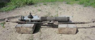
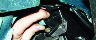
First you should measure the pressure in the fuel system. The regulator on this engine is located on the fuel rail. On the left as the car moves. On the right side of the ramp there is a fitting for connecting a pressure gauge.
To connect the pressure gauge, unscrew the plastic cap and nipple. The nipple can be unscrewed with a metal cap from a regular camera. The external thread size for connecting a pressure gauge is 10 mm. You can contrive to put a VAZ fuel hose on it. You must first make an internal chamfer in it, otherwise it will be difficult to put it on the fitting.
To relieve pressure in the system, remove the fuel pump fuse and start the car. When the engine starts to shake, turn off the ignition.
How to check on a diesel engine
Checking the fuel pressure regulator on modern Common Rail diesel systems is limited only to measuring the internal electrical resistance of the sensor control inductive coil. In most cases, the corresponding value is around 8 ohms (the exact value must be clarified in additional sources - manuals). If the resistance value is obviously too low or too high, it means the regulator has failed. More detailed diagnostics are only possible in a car service center at specialized stands, where not only sensors are checked, but also the entire common rail fuel system control system.
Fuel pressure gauge
Now connect the pressure gauge and tighten it with clamps. Turn on the ignition and start the car. Normal pressure in the fuel system is 2.8-3 atm.
The fuel pressure regulator is configured to dump excess fuel back into the tank when the pressure reaches above 0.3 MPa (3 atmospheres). The data is indicated on the pressure regulator itself.
My pressure gauge has a knocked-off reference point by 3 divisions (0.03 MPa), so taking this correction into account, the following figures were obtained. 0.23 MPa at idle (0.26 MPa on the pressure gauge). This is not enough for normal fuel atomization and the creation of an air-fuel mixture, so the engine was a little “wobbly”.
Checking the fuel pressure regulator
To further check the regulator, remove the vacuum hose from the RTD. It is connected to the intake manifold and controls the operation of the valve. If the pressure returns to normal (as in my case). It became 0.3 MPa. This means that the fuel pump is working and the reason for the low fuel pressure in the rail is in the regulator (also known as a check valve).
Replacing the fuse
Removing and installing the fuel filter VAZ 2110-2111-2112
One of the most common causes of breakdown is failure of the protective element. A clue that the fuse for the cigarette lighter has blown will be a non-working VAZ 2110 stove or a faulty glove compartment illumination lamp. To carry out repairs, it is necessary to replace the blown fuse in the mounting block.
To get to the box, press the button in the front panel to the left of the steering wheel. The fuse to be checked is number F18, rated for a current of 25 amperes. It is convenient to use tweezers for replacement.
A fuse of the recommended rating should be installed. Otherwise, there is a high risk of insulation melting, short circuit, and fire. After repair, you cannot connect powerful devices to the cigarette lighter socket. The maximum power is 300 watts. Calculated using the formula P=I*A, where I is the network voltage (12 volts), and A is the amperage (25 amperes).
How to replace the throttle cable on a VAZ 2110-VAZ 2112
Air filter mount for VAZ 2110 2111 2112 2109 2108
Note! Replace the cable on a cold engine, and in general you should only climb into the engine when it is cold, so as not to get burned on it during any work, replacing or adjusting parts!
Another thing they wanted to warn you about, this article shows an example of replacing the cable on two engines, namely on an injection 8 valve engine and on an injection 16 valve engine, but not a word is said about a carburetor engine in this article, so if you have a car with carburetor engine and you need to replace this throttle cable, then in this case read the article entitled: “Replacing the throttle cable on carburetor cars of the ninth family”!
Removal: 1) First, we recommend removing the air pipe, because it will interfere with the removal and installation of a new cable, it can be removed very easily, to do this, loosen the screws on both sides that are tightened by the clamps and then remove the hose (The location of the screws is indicated by arrows) , but also disconnect the crankcase ventilation hose; it is attached to this pipe in the middle part using the same clamp, which you will have to loosen with a screwdriver.
2) Then, using the same screwdriver, pry up the locking spring that holds the sector and thereby remove it (see photo 1), then turn the sector counterclockwise by hand and remove the throttle cable from the slot into which it goes (see photo 2 ), thanks to this operation you will already disconnect the cable from the throttle assembly, then all you have left is the little things and by the way, on different engines (on 8 valve and 16) this operation is the initial one (which is described in this paragraph 2) and it is done absolutely identically.
3) Now (This only applies to 16 valve machines), using thin pliers or something similar, remove the locking plate thanks to which the cable adjustment is carried out (see photo 1) and as soon as it is removed, remove the middle part of the cable together with the rubber holder from bracket on the intake manifold as shown in the second photo.
4) But on 8 valves, the cable in the middle part is attached slightly differently and to disconnect it, you will first need to move the rubber boot (Indicated by number 3 in the first photo) to the side and loosen the nut under number 2, remove the middle part of the cable from the bracket and then ( This already applies to both engines) you can either pull the cable itself together with the sheath through a plastic clamp, thereby removing it, or you can cut this same clamp with pliers (But in this case a new clamp will be needed, see photo 2) and without any hemorrhoids you can move on, and then you will need to climb into the car interior and disconnect the tip of the cable from the gas pedal, this is done very easily and with the help of a screwdriver (see photo 3) and finally you will need to go from the engine compartment of the car, pull the cable out of the cabin and thus remove it completely from the car (see photo 4).
Installation: The new cable is put into place in the reverse order of removal, you need to insert it through the engine compartment and push the end into the passenger compartment where it aligns with the gas pedal, when the entire installation operation is done, adjust the throttle cable on the car, how to do it read the article: “Adjusting the cable on a car”
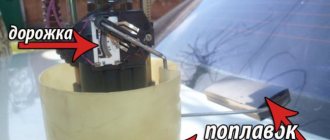
How regulators work
The fuel rail is necessary to mix gasoline vapors and clean air. It maintains pressure at 2.9-3.3 kgf/sq. cm due to the pressure regulator. For injection, injectors with a solenoid valve are used. A regulator is connected to them, which is a valve made of a membrane. The device inlet is from the ramp side, the outlet is on the fuel drain line. A tube from the intake manifold is connected to the VAZ-2110 fuel pressure regulator.
The pressure is adjusted using a spring; its rigidity is selected so that it compresses only with a certain force. If the pressure of the fuel mixture in the rail exceeds 3.3 kgf/sq. cm, then the spring compresses, the valve opens and the excess is released into the return line. When the pressure reaches 2.9 kgf/sq. see the valve closes.
Location of fuses on the diagram for VAZ 2110, 2112
The mounting block is installed in the front panel, to the left of the steering wheel. It’s easy to get there – just press the corresponding button (see photo). On the back cover there is a diagram of the location of the fuses. Each of them protects a separate device or section of the circuit.
| Number, F | Current indicator, ampere | Purpose |
| 1 | 5 | Illumination of license plate, tidy, trunk and dimensions lamps |
| 2 | 7,5 | Low beam left headlight |
| 3 | 10 | High beam left |
| 4 | 10 | Right fog light |
| 5 | 30 | Electric window drive |
| 6 | 15 | portable lamp |
| 7 | 20 | Cooling fan motors, horn |
| 8 | 20 | Rear window heating elements |
| 9 | 20 | Recirculation valve, windshield and headlight washer |
| 10 | 20 | Backup fuse |
| 11 | 5 | Right clearance |
| 12 | 10 | Low beam right headlight |
| 13 | 10 | High beam right headlight |
| 14 | 10 | Left fog light |
| 15 | 20 | Electrically heated front passenger and driver seats |
| 16 | 10 | Right-left turn signals, emergency lights |
| 17 | 7,5 | Interior lamp, brake lights, button illumination and trip computer |
| 18 | 25 | Fuse for illumination of the glove box, radio, interior heater and cigarette lighter of VAZ 2112 |
| 19 | 10 | Locking door locks, panel warning lamps indicating faulty brake lights or parking lights |
| 20 | 7,5 | Taillight fog lights |
There is an additional block with the main relays. Its location is in line with the injector, behind the right decorative panel, near the passenger’s feet. To get to it, you need to unscrew the three fastening screws. There are six fuses located here (see photo), each of which performs its own function.
- Operation of the ignition system software controller.
- Regulator for air flow meter, speedometer drive.
- Fuel injectors.
- Radiator cooling fan.
- Gasoline pump.
- Ignition system.
Repair of VAZ 2110 16 valves
Installing piston rings
and pistons into cylinders yourself!
VAZ
! Decreased vehicle performance.
Installing piston rings
1. Carefully clean the piston of carbon and deposits. We inspect the piston, connecting rod and pin. Cracks are unacceptable. 4. We select new rings in accordance with the piston class (see paragraph 5 Piston and connecting rod. change).
NOTE There are no markings on the piston rings of the nominal size; repair piston rings are increased in diameter by 0.4 or 0.8 mm, and are marked “40” and “80”, respectively.
See:
3. Before installing new piston rings, use a set of feeler gauges to measure the gap between the piston ring and the wall of the piston groove where the ring will be installed. If the gap exceeds the permissible limit, then the piston must be replaced. Oil control piston ring. and install the upper compression ring with the inscription “VAZ” or “TOR” up. We orient the lower compression ring in such a way that the groove is oriented downwards. 4. We put the piston rings on the piston in this way: by spreading the piston ring lock
(less than what is required to put the piston ring on the piston), first place the lock on the piston, and then the back part of the piston ring.
We install new piston rings on the piston, starting with the development of the oil ring expander. After installing the oil scraper ring, the expander lock must be rotated 180° relative to the piston ring lock. After installing the piston rings on the piston, we rotate them with locks so that the lock of the upper compression ring is placed at an angle of 45° to the piston pin axis, the lock of the lower compression ring is rotated 180°, and the lock of the oil ring is 90° relative to the lock of the upper compression ring. 5. Lubricate the piston, rings and cylinder mirror with the freshest engine oil. 6. We put the mandrel on the piston and compress the rings with it, from time to time slightly tapping the mandrel with the handle of a hammer to self-install the piston rings. 7. We wipe dry the beds of the connecting rod bearings in the connecting rod and the cover and install the bearings in the lower head of the connecting rod.
NOTE The selection of connecting rod bearings for the crankshaft journals is shown below (see Table 8.1.34). If the crankshaft has not been bored, then it is better to replace the connecting rod bearings with new ones of the nominal size.
8. Lubricate the inner surface of the connecting rod bearings and the connecting rod journal of the crankshaft with clean engine oil. By turning the crankshaft, we move the neck to the last lower position. 9. Install the piston on the block and orient it so that the arrow on the bottom of the piston is oriented towards the crankshaft pulley (see Piston and connecting rod. change). 10. Pressing the mandrel against the block and tapping the piston bottom with the handle of a hammer, we recess it into the cylinder, immediately monitoring the movement of the connecting rod to the crankshaft
. 11. Install the cover on the connecting rod and tighten the nuts to a torque of 43.3-53.5 Nm (4.4-5.5 kgf-m).
WARNING The connecting rod caps are not interchangeable. The number of the cylinder in which the connecting rod is installed is indicated on the connecting rod and its cover. On the assembled connecting rod, the numbers must be placed on the positive side.
12. We replace the piston rings of the other 3 pistons using the same method. 13. After installing all the pistons, we assemble the engine in the reverse order of its disassembly. See also Piston and connecting rod. change
What is a fuel pressure regulator? Operating principle, RTD device and its malfunctions
Today we will talk about the fuel pressure regulator, which is an integral part of the fuel system. To begin with, I suggest you figure out why you need an RTD? The regulator is necessary to control the pressure of the fuel that is injected into the combustion chamber, for the correct operation of the fuel injectors and to create pressure in the fuel rail. The RTD is located in the fuel rail, however, if the fuel rail is not equipped with a recirculation system, the regulator can be installed in the fuel tank. The RTD maintains the pressure difference, controls the pressure in the intake manifold, as well as in the injector. Excess fuel flows back into the tank via the return line.
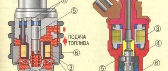
Operating principle of the fuel pressure regulator
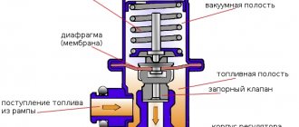
The RTD is a diaphragm safety valve, which is pressed on one side by the fuel pressure, and on the other by the regulator spring, as well as the air flow in the intake manifold. Sometimes, after you turn off the engine, the valve does not work, resulting in excess fuel not returning to the tank. At the same time, the pressure in the fuel system increases, sometimes up to 3 or even 5 kg/sq.m. cm (norm – 2 kg/sq. cm). As a result, due to the increase in pressure in the fuel system, fuel consumption increases, and the injectors simply overflow excess fuel, which squeezes out excessive pressure.
Ideally, the fuel pressure regulator should monitor and maintain system pressure after the engine is stopped. However, constant loads lead to wear on the valve, and in order to restart the engine, you have to turn the starter for a long time until the required pressure is generated.
Another situation also happens when the valve does not work and does not create the required pressure, as a result the circulation of fuel is disrupted, which is not supplied under pressure, but flows by gravity, as a result, at high speeds there will be an acute fuel shortage, power will decrease and dynamics will deteriorate.
RTD malfunctions and signs of failure
- The valve does not hold pressure. The reason may be that the spring is weakened or worn out, due to which there is simply no pressure. In this case, due to a pressure deficiency, there will be a shortage of fuel, power will decrease, and dynamics will deteriorate.
- Obstructed movement of fuel in the system. This malfunction will cause starting problems.
- Blockage (wedging) of the RTD. The result will be an uneven and untimely change in pressure. While driving, this means problems with acceleration, fraught with loss of dynamics, and jerking while driving. Also, valve wedging can manifest itself in the form of unstable operation at idle, the car may stall when the tank is full.
- The engine loses power and throttle response decreases.
- Increased fuel consumption. This usually occurs due to excessive pressure in the fuel system.
How to check the fuel pressure regulator?
- The principle is almost the same as when checking the pressure in the fuel rail. It is necessary to unscrew the fitting plug that controls the fuel pressure.
- Inspect the sealing ring; if it is damaged, the ring must be replaced.
- Next, you should unscrew the spool from the fitting.
- Using a pressure gauge, measure the pressure in the RTD while the engine is running.
- Compare the obtained figures with those indicated by the manufacturer.
If the assumption that the RTD is faulty is confirmed, replace it; the part is inexpensive, and the replacement itself will not take much time and effort.
Text belongs to: VAZ DIY repair
Possible signs of failure
If the fuel pressure regulator for some reason does not perform certain functions, this can be determined by the following signs:
- Unstable engine operation, it may stall when idling, although the fuel level seems to be sufficient and all systems are in working order.
- Increased or decreased crankshaft speed;
- The engine “loses throttle response.”
- The occurrence of dips and jerks in a running engine while driving.
- Increased gasoline consumption compared to what it was before;
- Increased CO and CH content in the exhaust.
- Starting the engine is carried out with great difficulty, but this property is not always clearly manifested.
The process of cleaning injectors on a VAZ-2110
Before cleaning, it is necessary to realize that the motorist knows the design and operating principle of the unit, as well as the degree of responsibility for all operations performed and their consequences. If you are not so sure, it is recommended to contact a car service.
Bosch injectors for VAZ-2110.
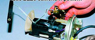
To begin with, it is necessary to dismantle the elements from the fuel line and completely remove them from the car. This was done for the convenience of transactions. So, let's start disassembling the unit and dismantling it:
- The engine has cooled down and operations can begin. De-energize the fuel pump. This can be done by turning off the fuse or removing the wire blocks from the power connector.
- We reduce the pressure in the fuel line.
Disconnect power from the fuel pump and relieve pressure. - We completely remove the terminal from the battery, since we will have to remove the ramp assembly.
Remove the battery terminal to remove the fuel rail. - Disconnect all wires connected to the fuel rail.
- Remove the fuel supply pipe.
Once everything is disconnected, you can remove the fuel rail from the engine. - Using a hexagon, unscrew the fastening bolts of the ramp and remove it along with the injectors.
Having disconnected the fuel hose, we dismantle the fuel rail. - Disconnect the mounting brackets and remove the injectors.
We remove the fastening brackets and dismantle the injectors from the ramp.
The injector seats must be covered to prevent foreign objects from getting into the manifold and cylinders, which could damage engine components.
After the injectors are removed from the car, you can proceed directly to the cleaning process:
>
- We remove the rubber seal from the nozzle itself.
- Using a special nozzle cleaner, we wash the funnel-shaped surfaces and nozzles.
- Next, we clean the fuel supply channel.
- When manual cleaning is done, it is worth moving on to a more effective method.
Do-it-yourself procedure for connecting and cleaning injectors. - To do this, connect power to the injector. It is not recommended to use a standard car battery, since you can burn the injector winding and you will have to buy a new one. Ideal for mobile phone power supplies (charging).
- Using a standard syringe (used as an adapter) we connect a can of liquid for cleaning carburetors.
- After this, turn on the power for a few seconds. Do this several times until the stream from the nozzle becomes uniform. This operation must be carried out with each nozzle.
Cleaning methods
In practice, there are several types of injector cleaning. The most famous and used three methods:
Nozzle dirty.
- The first method involves the use of automotive chemicals. A very effective, but significantly expensive method. To everything else, we can add that automotive chemicals are not safe to use for the human body, and therefore you should be extremely careful. When using chemicals, the nozzles do not need to be removed!
- Car service. Of course, this is the safest and most reliable way to clean injectors using a special stand. The obvious disadvantages include the cost of performing such work, since the price is often too high.
- Do-it-yourself injector cleaning. The most profitable and economical method of repair and restoration work on the fuel system. In this case, the car owner needs knowledge of the structure and operation of the elements, so as not to screw up anything, and also not to increase the cost of repairs.
Symptoms of a problem
If you clean and maintain the injector assembly in a timely manner, they can last quite a long time. But when to clean the elements is difficult to determine, so there are a number of signs of malfunction.
- Starting the engine with difficulties or not the first time.
- Loss of power and traction.
- Troubling is a clear sign of uneven fuel supply.
- Increased consumption.
- Jerking of the vehicle in the winter season.
If the above symptoms occur, it is necessary to urgently clean the injectors. After the procedure, the performance of the car engine should return to normal. If this does not happen, then you should look for reasons in another place, such as the fuel pump, fuel filter or cylinders.
Cleaning and preventing plaque in the system
The injector device is very sensitive to large inclusions in gasoline. If you are using a cheap brand of fuel, be prepared to change your injectors soon. So the first thing you should do for your VAZ fuel pump is change the brand of fuel. The power supply system of the VAZ 2107 should become cleaner; the possibility of plaque formation in the system is still not excluded. Since the flammable liquid in the channels occasionally stagnates and sometimes even freezes, an early breakdown can be prevented only in one way - regular cleaning.
Approximately every 35-40 thousand km it is necessary to carry out preventive cleaning work on the fuel system. You need to wash the channels with your own hands. The performance of the engine will depend on the quality of cleaning. If this procedure is carried out irregularly, then soon you can say goodbye to one injector and look for a new one, and then you will have to change the remaining elements of the VAZ fuel pump.
In 4-cylinder types of injection engines, different intensities of injector clogging are observed. The temperature in the area of cylinders 2 and 3 is always elevated, so sediment accumulation occurs there faster.
A special admixture of polyetheramine is considered a prophylactic agent in such cases. It prevents the accumulation of burning for a long time.
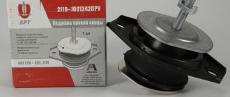
Replacing fuel pressure regulator VAZ-2112 16 valves with photo
The fuel pressure regulator, or simply abbreviated as (FLS - approx.) on the VAZ-2112, is designed to ensure that operating pressure is constantly maintained in the vehicle’s fuel system. And if this element malfunctions, it may require replacement. We described in detail how to do this correctly below in our article.
The video describes in detail the process of replacing the fuel pressure regulator on the VAZ-2112 (and other cars of the LADA family):
Replacement process for a 16-valve VAZ-2112
If the regulator is still faulty, we replace it in the following order:
We disconnect the negative terminal from the battery for fire safety. Next, we reduce the pressure in the fuel system by unscrewing the nut that secures the fuel line and the RTD to each other. To avoid fuel spills, place a rag. Using a “10” wrench, unscrew the bolt holding the guide and move it to the side
We remove the bolts that hold the RTD on the ramp. You will have to dismantle the bolts using hexagons. We remove the fitting from the fuel rail and remove the RTD. When dismantling, be careful. We install the new regulator in the same reverse order as removal. When connecting, pay due attention to the condition of the o-rings.
Attention! Before installing a new regulator, lubricate the O-rings with gasoline, so they will retain their elasticity longer and will be less susceptible to cracking
Signs of a faulty RTD?
You can understand that the regulator is not performing its functions by the behavior of the car, and they are expressed as follows:
All these reasons have one thing in common: during operation, the fuel pump releases much more gasoline into the system than required, as a result of which it does not burn out completely, which causes gasoline consumption to increase.
Checking the fuel pressure regulator
If you have checked and are already sure that your FLS (fuel level sensor - approx.) is working, but you simply have fuel consumption and other problems indicating it, then you must first check the regulator as follows:
We unscrew the fitting plug, which is designed to control fuel pressure.
Please note that if it has lost its elasticity, has cracks or other damage, it needs to be replaced. Location of the fitting plug on the editorial machine (though ours is an 8-valve). Pay attention to the condition of the O-ring inside. We unscrew the spool valve from the fitting, as is done on any tire. This element is also worth checking for serviceability. Connect a regular tire pressure gauge to it, and measure the readings with the engine running.
If they fluctuate within the limits (by 0.2 - 0.5 kgf/cm2), then the regulator is working; if there is nothing like that, then it needs replacement. When connecting the pressure gauge, make sure that all connections are tight.
In stores, the price of a new RTD is in the range of 300-600 rubles, such a range in price results from the presence of a large number of analogues from different manufacturers.
What is a fuel pressure regulator (FPR)?
The fuel pressure regulator is a part mounted on the fuel rail, slightly larger than a matchbox, which operates on the principle of a diaphragm valve.
On one side, fuel is supplied, and on the other (where a special spring is located - approx.) air is supplied from the intake manifold.
Preparatory work
- We take a pre-prepared pressure gauge, and to prevent fuel spills and air leakage, we wrap flax or fum tape around the tip.
- We are preparing a hose with a maximum internal diameter of 9 millimeters, and clamps will be needed to secure them.
- We place the prepared rags on the engine in such a way that the hose and pressure gauge fixed on it cannot roll off the surface. This is done to prevent excess fuel from spilling over the surface of the engine.
- We wrap flax or tape around the pressure gauge, then fix the hose on it and tighten everything with a clamp.
- On the ramp, unscrew the spool valve from the nipple (in this case, fuel splashes are possible due to the presence of residual pressure - approx.).
A regular wheel cap came in handy.
We put a hose with a pressure gauge on the ramp connections and secure everything with a clamp.
Pressure gauge with pipe assembly.
We place the pressure gauge on a previously prepared rag, and the preparatory work can be considered completed.
Measurement procedure
Before you start working, you can try to relieve the pressure in the fuel system. To do this, remove the fuel pump fuse (which is located on the right side of the panel, under the front passenger’s left foot - approx.). Where 3 relays and 3 fuses are located. In the photo below it is located under the number “5”. After removing the fuse, turn on the ignition and check by ear that the fuel pump is not pumping. We start the car and wait for the engine to stall.
- After everything is ready, we check the already attached end of the pressure gauge with the hose for a secure connection.
- Next, start the engine and look at the readings that appear.
Thus, we diagnose the results that appear and compare them with the results of the norm.
After all the work has been done, unscrew the hose with the pressure gauge, screw in the spool and return everything to its original state.
Note!
The peculiarity of measuring pressure using a pressure gauge is such that its initial value on the scale has a certain inaccuracy. That is, when the air analogue has a measurement period of 15-20 atmospheres, and for fuel control the required maximum value is 5-7 atmospheres, then all measurements taken will have an error equal to the initial values on the device. Therefore, pressure testing should be carried out on a pressure gauge with maximum values of up to 8 atmospheres.