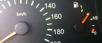
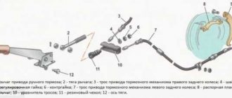
Car : VAZ-2112. Asks : Petrov Viktor. The essence of the question : It incorrectly shows the fuel level in the gas tank or does not show anything at all, it sits at zero.
Hello! I have a problem that the arrow does not correctly show the level of fuel that is in the gas tank. It happens that the arrow either increases or decreases the actual availability of gasoline, and recently it even started pointing to an empty tank, although I know for sure that there is still more than half there. What to do?
Adjusting the readings
If the arrow periodically increases and decreases the values, then adjustment will help in this case.
Adjusting the fuel sensor (FLS) - removing the fuel pump
- Raise the rear sofa.
- We remove the fuel pump and clean everything from dirt. (More information about removing the fuel pump here).
Preparing to remove the fuel pump
If in any position the arrow indicates incorrect values, then it is necessary to bend the adjusting tongues on this side so that the float rod can move to the right or left freely, depending on its location.
Adjusting the control arrow on the instrument panel
If the problem is the arrow on the instrument panel, then you need to remove the instrument panel and adjust it manually.
Broken ground contacts
This problem manifests itself on the panel by displaying incorrect information; the tachometer needle may drop below the current level. The needles of other instruments may also freeze, either permanently or for a short period of time. The panel backlight may also disappear, but the arrows will show the correct data.
Bolt for fixing ground wires from all devices
Through trial and error, it was found that these glitches can occur due to the fact that the ground contact is broken. Under the dashboard, near the driver’s right foot (near the gas pedal), there is a special mount to which ground wires from all instruments are fixed.
To solve such a malfunction in the operation of the VDO dashboard, you simply need to improve the contact. Unscrew the bolt at “8”, disconnect and clean all contacts suitable for it. To be safe, it is advisable to treat them with “electronic contact cleaner”. After this, all that remains is to connect the wires and screw the bolt back.
Bottom line of the route display
If you have stopped switching the parameters that are displayed in the bottom line of the route display (under the total or daily mileage), then the problem lies in the steering column switch.
It is responsible for switching between the following options:
- current time;
- outside air temperature;
The buttons on the switch work every once in a while
- travel time (valid from the last reset);
- average fuel consumption;
- instantaneous fuel consumption (changes as the vehicle moves);
- average speed since reset;
- residual power reserve with the remaining fuel in the tank;
- amount of gasoline consumed since reset.
Is it possible to install an air conditioner on a VAZ 2110?
Yes, the design of the VAZ 2110 car initially included the possibility of installing an air conditioner. Moreover, when the “tens” were still being produced (and they stopped producing them in 2009), the car could be purchased complete with factory air conditioning. But not everyone could afford such a purchase, since the price of the car increased by almost a third. That is why many VAZ 2110 owners had to install air conditioners later. To install this device in a car, it does not have to be modified. There is no need to make additional ventilation holes in the dashboard. There is no need to lay separate lines for pipes and electrical wiring in the engine compartment. There is already a place for all this. This means that installing an air conditioner in a VAZ 2110 is completely legal, and no questions will arise for the car owner during inspection.
About the features of installing air conditioning on cars with different engines
The VAZ 2110 was equipped with various engines - 8 and 16 valves. They differed not only in power, but also in size. These points should be taken into account when choosing an air conditioner. Here's what to remember:
- The condenser for the air conditioner for a 16-valve engine is larger. It is 4 cm wider, 2 cm taller and 920 grams heavier;
- all mounting holes in the condenser for a 16-valve car are shifted 1.5 cm downward;
- The pipes for the cooling circuit of a 16-valve car, as well as the electrical wiring harness, are approximately 8 cm longer.
Otherwise, air conditioners for cars with different engines are identical, and they have no fundamental design differences.
About choosing an air conditioner for a VAZ 2110
If the driver decides to install the air conditioner on the “ten”, the choice of models will be small:
"Frost." The most popular manufacturer among domestic car enthusiasts. It produces air conditioners for many VAZ models, including the VAZ 2110. Catalog number - 217ОF-8100046–83. The advantage is the affordable price, which starts from 12 thousand rubles. The disadvantage is the lack of a damper on the heater. The device is also noted to be highly inert (i.e., the air conditioner takes 2–3 minutes to change temperature).
But these shortcomings can hardly be called significant, and Frost today is the optimal choice for the VAZ 2110;
Diagnostics using additional tools
To diagnose cars, including the VAZ 2110, various equipment is used, which is connected to a special connector. Thanks to this equipment, which is not particularly complicated or expensive, you can get a complete picture of the condition of the car.
The service station uses a personal computer to which data from phase sensors is transmitted via a special cable.
Bluetooth devices have appeared on the market that allow diagnostics using a smartphone, tablet or laptop.
They work according to the scheme. The device is connected to the connector, the ignition is turned on and the diagnostic process begins. The data comes from phase sensors to the ECU. From it to a mobile device on which specialized software must first be installed.
This makes it possible not only to obtain more data, but also to present it in a more visual form. This method allows a driver, even with little experience in operating a car (in our case, a VAZ 2110), to obtain all the data about his car.
But most drivers prefer to carry out diagnostics at a service station. So that you are aware of the data that the on-board computer produces through RAM from the phase sensors, we will present the transcripts of common errors.
Crankshaft regulator
New crankshaft controller for the “ten” Depending on the type of car, on a 16- and 8-valve engine, the location of all controllers may be different.
However, all of these devices combine into one functioning system, and the crankshaft adjuster is no exception. Thanks to this controller, the electronic engine management system of the “tens” can independently determine at what point to supply gasoline and a spark through the spark plugs in order to ignite the combustible mixture. In fact, the design of the device is a magnet, as well as a coil of thin wire. The crankshaft sensor has certain advantages:
- As practice shows, at “tens” this regulator can work for quite a long time. Its service life does not decrease even as a result of using the vehicle’s power unit under increased loads.
- The crankshaft adjuster works in conjunction with the crankshaft pulley.
- If the device fails, the engine may not be able to start. Or, if the regulator breaks down, the speed parameters will be reduced to 3.5 thousand per minute.
This controller is installed on the oil pump, actually at the very top of the shaft teeth. Or rather, one millimeter from the cloves. You can learn more about how to replace this controller yourself from the video below (the author of the video is the channel In Sandro’s Garage).
Replacing the fuel level sensor (detailed test)
As we already know, the sensor is mounted in the fuel module, which, in addition to the sensor, includes a fuel pump and filters. To dismantle we do the following:
- Remove the negative terminal of the battery.
- Remove the rear seat cushion.
- We bend the floor covering and clean the fuel module hatch from dirt and dust.
- We remove the hatch.
- Disconnect the contact blocks from the power module.
- We disconnect the fuel line - two fittings using a 17 key, and move the tubes to the side.
- Using a 7 socket and a ratchet wrench, unscrew the pressure washer.
- All that remains is to carefully remove the entire fuel module assembly from the tank.
- Using a Phillips screwdriver, unscrew the screws securing the sensor from the module body.
- Bend the clamps with a screwdriver and remove the guides.
- Unscrew the nuts (key size 5) securing the cover and separate the sensor from the pump.
Now you can test the sensor in more detail. The working device must have a resistance of 270 to 320 Ohms at the lowest point (the float hangs). At the highest point, the sensor resistance should be in the range of 7–19 ohms. We take this data using a multimeter in resistance measurement mode.
When the level of gasoline in the tank is equal to half its volume, the resistance should be about 118 Ohms.
Assembling the fuel module with a new sensor is carried out in the reverse order. During assembly, it is advisable to lubricate the sealing ring of the pressure washer with petrol-resistant sealant.
Mass air flow sensor
The power unit of the "tens" is controlled using the ECM - an electronic system. This system must always know how much air needs to be supplied for a certain volume of gasoline. These two parameters are closely related to each other, since with their help a combustible mixture with the required density is formed in the engine power unit. After the system determines the required volume of air, it begins to select the appropriate amount of gasoline. As for the regulator, it is responsible for the suction volumes.
Air controller for "ten"
This controller has certain disadvantages, in particular:
- its performance may be impaired if the controller is exposed to moisture;
- if the car is moving at lower speeds, the controller can produce higher readings;
- as practice shows, at idle the air regulator does not work entirely correctly;
- when starting the power unit, certain difficulties may arise;
- the power unit may stop abruptly for no reason after an increased power mode;
- Gasoline consumption during vehicle operation may increase.
We've dealt with the shortcomings, now let's talk about how the device functions:
- The controller design consists of several sensitive elements installed directly in the line itself through which the air flow passes. One of these components is designed to fix the temperature of the air flow, and the other two are always heated to the required parameters.
- To correctly determine the air flow rate, the principle of measuring electrical power is used to maintain the desired temperature level.
- The air regulator controller has a special mesh installed in the line, designed to filter the air flow.
- Thanks to this, the sensor can transmit the necessary data to other regulators designed to activate certain modes. Subsequently, these regulators either change or support the loads.
Checking the steering column switch
Checking the contacts in the steering column switch housing
In those cases, switching between the BC readings on the panel should be done with a switch on the steering wheel, but this cannot be done - you should make sure that it is working. This steering column switch is used on the panels: “VDO” 1118-3801010, “Schetmash” 2170-3801010-01 and “Avtopribor” 1118-3801010-02. To check whether the steering column switch is working properly, it must be removed and disassembled.
Disassembling the switch consists only of removing the cover, which is held in place by a small metal latch in the form of a bracket. There are 4 contacts under the cover, which are connected to the Reset button and to the switches. There are yellow and black wires coming from the “Reset” button. There are green and red wires coming from the top switch button. All these contacts must be checked with a multimeter for resistance.
If it is, then everything is fine with the switch and you need to disassemble the dashboard to inspect the contacts and tracks. On VDO panels with one window produced in 2006-2007, there is a factory defect - poor contact of one of the resistors, which, during driving, cracks and interrupts the connection between the steering column switch and the panel board.
Fuel level sensor (FLS) for VAZ 2108, 2109, 21099 cars
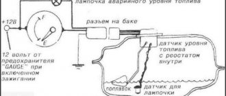
In the power supply system of the carburetor engine of VAZ 2108, 2109, 21099 cars, a fuel level sensor (FLS) is installed, designed to monitor the amount of gasoline in the fuel tank. It is located on the fuel intake in the vehicle's fuel tank. On the instrument panel there is a fuel level indicator and a fuel reserve lamp (indicator), connected by an electrical circuit to the fuel level sensor and transmitting information from it directly to the driver.
Fuel sensor device for VAZ 2108, 2109, 21099 cars
The fuel level sensor (FLS) has a round flange that is attached directly to the fuel tank. There is a sensor connection block with two terminals on the flange. A fuel intake pipe and a return pipe are welded to it. The sensor itself has a plastic housing mounted on a support plate. Inside the housing there is a rheostat with a winding of nichrome wire and a fixed contact for turning on the fuel reserve lamp. The contact is connected to the sensor block (terminal “W”). The rheostat has a slider mounted on a rotating axis and connected to a movable lever, at the end of which a sealed plastic float is installed. The lower end of the rheostat is connected to the sensor block.
The principle of operation of the fuel level sensor for VAZ 2108, 2109, 21099 cars
The float moves down or up when the fuel level in the gas tank drops or increases. At the same time, the slider connected to it moves along the rheostat winding, changing the resistance at the output of the rheostat from low to high and back. A drop and increase in resistance is reflected in the movement of the needle on the fuel level indicator in the instrument panel. The level in the tank is low, the float is lowered - resistance is 285-335 Ohms (the fuel level indicator arrow is at zero), the indicator arrow shows the tank half - resistance is 100-135 Ohms, the tank is full (the arrow is all the way to the right, the float is raised) - 7-25 Ohms .
In the lower position of the float, when the fuel level is at its lowest (4-7 l), the contacts on the slider and the contact of the fuel reserve lamp close. The lamp on the instrument panel lights up.
Operation of the fuel level sensor (FLS) with a full tank: the float has floated up, the slider contact at the bottom of the rheostat (minimum resistance), the moving and fixed contacts of the fuel reserve indicator lamp are open (the lamp does not light up)
Operation of the fuel level sensor when the fuel level in the fuel tank of a car drops: the float fell, the slider contact moved up the rheostat winding (maximum resistance), the moving and fixed contacts of the fuel reserve lamp closed (the lamp lit up)
More information about how the fuel level indicator and sensor works: “VAZ 21083 fuel level indicator, diagram.”
Applicability of the fuel level sensor on VAZ 2108, 2109, 21099 cars
On VAZ 2108, 2109, 21099 cars and their modifications, fuel level sensor 24.3827 and its variants are used. Its characteristics are as follows: voltage -12 V, rheostat impedance - 350 Ohm, float lever length - 115 mm, lever angle when the tank is empty - 27.5 degrees.
Fuel level sensor malfunctions
If the fuel level sensor fails, the fuel level indicator in the instrument panel either does not work at all or displays incorrect information. For more information about the malfunction of the fuel level sensor, see “The fuel level indicator in the instrument panel of VAZ 2108, 2109, 21099 does not work.”
Notes and additions
— A rheostat is an electrical device that allows you to regulate the current and voltage in an electrical circuit by changing the resistance of the electric current passing through its winding. The slider, being a movable contact, moving along the turns of the rheostat winding (conductor), changes the number of turns included in the circuit, thereby changing the length of the conductor and, accordingly, its resistance.
Twokarburators VK - More information on the topic in our VKontakte group, on Facebook Twokarburators FS and on Odnoklassniki - Twokarburators OK
Common problems
The fuel volume control system in the gas tank is susceptible to the following malfunctions:
- the pointer indicator lies at zero regardless of the amount of fuel remaining in the tank;
- the device does not display the fuel level correctly - it is lying up or down;
- the needle “jumps” or changes readings in a short period of time;
- The yellow minimum fuel indicator indicator does not light up.
Reference. In some domestic car models, the fuel sensor is lying from the factory. An example is the Chevrolet Niva SUV of the first releases, where the device greatly underestimates the actual level of gasoline. The driver, guided by the sign, pulled into a gas station, only to discover that the tank was full to the top.
There are several reasons why the needle drops to zero:
- Sticking or jamming of the lever.
- The float lost its seal and sank to the bottom.
- An electrical circuit is broken due to oxidized contacts or a wiring problem.
- Failure of the indicator itself or the lever sensor - potentiometer.
Typically, incorrect readings and “jumps” of the needle are a consequence of contamination of the rheostat and slider. On a car with high mileage, these parts can wear out - the thin layer on the plates wears away, causing contact to disappear between them and the runner.
How to check the operation of the fuel pump?
First, you should check the fuse. To do this, check the instructions for its location. Next, you should check the voltage at the pump. Before doing this, be sure to check if everything is in order with the battery. The voltage at the fuel pump terminal must be checked using a multimeter or tester. The instruction manual always indicates the required voltage.
Using a tester, check the voltage supply to the fuse. Often this is where the electrical circuit breaks.
If the search does not yield results, then the voltage should be checked on the contacts themselves. All contacts must be in place and connected to ground. A broken contact or its oxidation leads to failure of the fuel pump system. If no broken contacts are detected, but the voltage drops by more than 1 volt, then the problem is in the wiring or oxidation of the contacts. There should be no short circuit in the wiring.
If, after checking the voltage, contacts and fuse, you do not find any problems, then the problem lies in the fuel pump itself. In this case, the fuel pump will most likely require replacement. In practice, it most often turns out that replacement is a last resort. First, you should try to restore and test the fuel pump again.
Before you check the fuel pump, you need to remember that, as mentioned above, pressure is the most important characteristic of the fuel pump, so it is worth measuring its level.
How to check the pressure in the fuel rail?
You will need a pressure gauge that measures pressure in the range from 7 to 10 atmospheres. If you choose a pressure gauge with a large margin, you risk getting less accurate measurement results. Specialized stores sell a kit for measuring pressure, but you can also design your own device.
If you want to assemble the device yourself, you will also need a hose with an internal diameter of 9 millimeters. You will also need plumbing tow, with which you can seal the connection between the pressure gauge and the tube. All parts are connected and tightened using a clamp. You will also need a car spool. Next you need to perform a series of actions:
- Place the car on a level surface that is prevented from rolling, turn off the ignition and open the hood.
- Check that the injection nozzles have access to the fuel rail.
- Find the fuel pressure plug and remove it. Then you should unscrew the nipple using the spool.
- Prepare an empty container (a regular bucket will do) and a clean rag. This is necessary to collect residual fuel, which under pressure can splash out in different directions. Therefore, take care of the safety of your skin (especially your face and eyes).
- Connect the device to the fitting and begin checking the mechanism.
Checking the pressure in the fuel rail should occur in four operating modes of the power unit:
- when the ignition is on;
- at idle engine speed;
- code the fuel pressure regulator tube is reset;
- when the drain tube is compressed.
Fuel rail pressure measurement results
The results may vary slightly for different car models, but in general they should be as follows:
- when the ignition is turned on, the pressure must be at least 3 atmospheres,
- at idle engine speed - at least 2.5 atmospheres,
- when the pressure regulator tube is reset - at least 3.3 atmospheres,
- when squeezing the drain tube - at least 7 atmospheres.
Fuel rail pressure fluctuates slightly during preparation. When you press the pedal, it suddenly takes on a value of 3 atmospheres; when you release the pedal, it drops to 2.5 atmospheres. When fuel enters the fuel system, turn off the ignition and begin observing the pressure gauge. The pressure in this case should drop to 0.7 bar and remain unchanged.
If the pressure drops to zero, there may be a problem with the fuel pressure regulator. In this case, the regulator must be replaced immediately. The cause could also be the fuel pump check valve.
It is necessary to observe the behavior of the pressure gauge even at 3,000 engine speeds. A drop in pressure will indicate a faulty fuel pump. Sometimes the fuel pump cannot reach the required pressure for a long time. In this case, the problem lies in a clogged fuel filter, which needs to be replaced, or in a dirty fuel pump mesh (read more about where the fuel filter is located).
If the above methods do not reveal a malfunction of the fuel pump, you will have to diagnose other units (DPZD, IAC, mass air flow sensor, compression in the engine and some other indicators and parts).
Description of "brains"
The VAZ 2110 is considered the first vehicle in the domestic automobile industry equipped with an injection engine. The power unit is controlled by an ECU, an electronic device that determines the basic parameters of engine operation in accordance with sensor signals. In fact, the ECU of a VAZ 2110, VAZ 2112 or any other model is the “brains” of the car, the operation of which affects the functionality of the vehicle as a whole.
Control controller in VAZ 2110
In the “Tens”, as well as the VAZ 2112, there are 16 valves and other models equipped with BOSCH 7.9.7 or January 7.2 systems, one M6 screw is installed in the head. From this screw the mass is taken to the ignition coils, and the mass is taken directly to the control model in the cabin. Typically, the mass is a welded stud mounted on the ECM bracket, particularly behind the center console, behind the left screen. In this case, the mass is transferred to the bracket through a pin, which is welded on the engine shield in the middle. It should also be noted that the nut on this stud is not usually tightened.
Control unit location
Now let's consider the location of the VAZ 2110 ECU. This device in the Ten is located under the center console, in its lower part, in particular, under the control panel. In order to gain access to the control module, you must remove the plastic panel on the passenger side, to do this you will have to use a Phillips screwdriver. Once you remove the cover, you will see many different wires, plugs, and safety devices. The controller itself is located behind them, it is screwed to the bar in a horizontal position.
The arrow indicates the location of the ECM module behind the center console
Typical malfunctions: their symptoms and causes
If the electronic engine management system malfunctions, this can lead to problems with the operation of the power unit. Unfortunately, ECU malfunctions in dozens of domestic cars are not uncommon, so the car owner should be aware of the main problems, as well as the reasons for their occurrence.
First, let's look at the symptoms of malfunctions:
As for the reasons, malfunctions in the electronic control unit can occur as a result of:
Diagnostics
There are two ways to diagnose the condition of car systems. Let's start with the first one, which does not involve the use of additional equipment.
To start the self-diagnosis function, you need to press a button that resets the mileage for the day. Turn on the ignition. You will see how the arrows on the instruments begin to move from one position to another. This means that the diagnostics of the VAZ 2110 has been launched and information has begun to flow from the phase sensors to the ECU. After the process is completed, the RAM will transmit numbers to the display that will show the state of the car’s systems.
Decoding combinations
When the self-diagnosis is completed and the number 0 is displayed, this means that everything is in order with the vehicle and all systems are working as expected:
- if 1 is displayed, this indicates that there are problems with the microprocessor or the RAM is failing;
- 4 — high voltage in the network, more than 16 V;
- if 8, then low.
If there is not one fault, but several, then a figure equal to the sum of faults will be displayed. If 6 lights up, then this will mean the sum of the numbers 2 and 4. If 14, then most likely there are three malfunctions at once, namely 2, 4 and 8.
The simplest diagnostics that is available to the driver without the use of additional equipment. It will, of course, help identify some faults, as well as show the condition of the components and systems of the VAZ 2110 as a whole. But to specifically identify all faults and decipher information coming from phase sensors, additional tools are needed. For example, the on-board computer STATE, which provides more data.
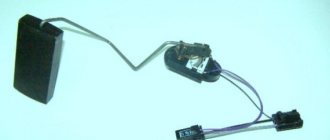
What is a fuel sensor
Advertisements
This small device is a rheostat with a resistor, which is assembled from nichrome components. The changing part of the rheostat in contact with the liquid moves using a lever with a float.
At the opposite end of the lever there is another contact, which, when in a specific position, closes a circuit that controls the start of production of spare fuel. The reserve balance ranges from 4 to 6.5 liters.
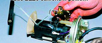
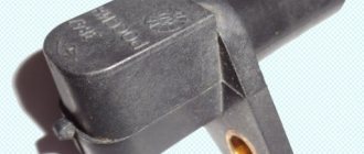
Sadly, this device (see photos at the beginning) is considered one of the elements that often fails. In some cases, replacing the fuel sensor may not be necessary, you just need to perform minor maintenance.
Device
The regulator includes two cavities - fuel and vacuum. Inside the vacuum there is a membrane that reacts to the air pressure coming from the power unit. Inside the fuel cavity there is fuel under high pressure.
The force of fuel pressure is resisted by a valve device. If the pressure is excessively high, the excess is returned back through the relief means.
How the regulator works
The fuel regulator ensures that the difference in influence on the membrane is maintained on both sides, that is, both cavities. Only under such conditions can the engine function normally.
The sensor serves to maintain pressure differences regardless of the current engine speed. Fuel injection will not be possible if the pressure in the manifold is equal to or greater than that in the injectors. Injectors are required to have higher pressures.
If everything works well, the following processes are observed:
- The vacuum in the suction cavity of the manifold is reduced during quiet operation;
- In response to this pressure, the fuel in the rail and its supply to the injectors increases.
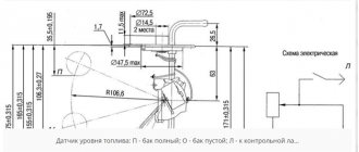
The principle of operation of the level sensor on the VAZ-2110
Operating principle of the fuel level sensor.
The vast majority of fuel level sensors in inexpensive cars have a similar design. The operation of the device is based on the principle of measuring the resistance of a simple rheostat.
VAZ fuel pump devices.
The stationary part of the device consists of nichrome contact tracks, and the moving part is a contact that cuts off part of the track, thereby changing the output resistance. As a result, we have a system that converts the sensor resistance into the amount of fuel indicated on the instrument panel. A spoke and a float are attached to the movable contact, which moves depending on the amount of gasoline in the tank.
The photo shows the scale of the fuel level sensor.
On the tenth VAZ family, the sensor is mounted in the same block with the fuel pump, fuel module. The sensor is capable of signaling a low fuel level (4–6 l), giving the unwary driver a chance to make it to the gas station.
To replace the fuel level sensor, they try to find original spare parts with article number 21101–3827010, 21102–3827010 or 2112–3827010. The price of a sensor assembled with a spoke and a float ranges from 350 rubles (Tochmash enterprise) to 420 (SEPO, Cartronic, Motorika).
It is better not to purchase spare parts of dubious origin. In any case, the new device must be compared with the old sensor.
Other fuel level sensor options
Potentiometric FLS has a number of limitations in its scope of application. Thus, it cannot be used on cars that use methyl, ethyl alcohol or biodiesel as engine fuel. This is due to the fact that such fuel acts more aggressively on electrical contacts and leads to their premature wear.
As an alternative, various non-contact sensors, such as MAAPS or an inactive magnetic position sensor, are used to measure the amount of fuel in the vehicle tank. The MAAPS sensing element does not come into contact with the fuel.
It has the following operating principle. Such a sensor determines the amount of fuel remaining in the tank using a float connected to a permanent magnet via a lever. The magnet moves along a sector on which a large number of plates of various lengths are deposited with rays. Electrical signals are formed in the plates under the influence of a magnetic field (different in each plate), depending on what signal the sensor gives, the remaining fuel is determined.
Troubleshooting VDO Instrument Panel Resistor
The problem described below appears only on VDO dashboards manufactured in 2006-2007 under article number 1118-3801010. It was installed from 2004 to 2011 on the Kalina, VAZ 2110, 2111, 2112, 2113 and 2114 models. We can recognize the manufacturer by its logo located under the inscription “km/h”:
Removed VDO instrument panel
This is due to a manufacturing error. On the dashboard board there are two resistors labeled “E6E”. One of these resistors was soldered crookedly. As a result of such defects, over time, cracks form in the solder due to which contact is lost and the on-board computer stops responding to the joystick of the steering column switch.
If the steering column switch is working properly, then this is definitely a problem in the “E6E” resistor!
What is needed to eliminate the VDO instrument disease
To complete the work you need:
- Soldering iron with fine tip.
- Solder (tin).
- Tweezers.
- Magnifying glass.
- Table fork.
- Screwdriver with star tip.
To diagnose this problem, you need to disassemble the dashboard. To do this, the dashboard is removed from the car and disassembled. And then the problem area on the board is inspected and soldered.
Disassembling the VDO dashboard
To disassemble the VDO panel, you need to snap off the front transparent plastic part of the panel, which is held on by six clips along the contour. Afterwards, the four star bolts are unscrewed and then the back cover is removed. After this, you need to snap off the black casing that remains on the front of the instrument panel. It is also held in place by plastic clips. This will allow you to remove the top glass and bottom cover from the dashboard.
Instrument panel with glass and bottom cover removed
To disassemble completely, remove the arrows and then unclip the latches from the board.
You can use a table fork to remove the arrows on the instrument panel from their seats. Before shooting, it is important to remember their location! The fork must be inserted under the arrow and, by gently pressing and rocking, tear it out of its seat.
The location of metal clamps in the center of the board and plastic ones at the edges
Then we proceed directly to removing the board from the remaining part of the instrument panel. To do this, you need to snap off the four metal clips in the center, as well as the four plastic clips along the contour. In the photo, these fasteners are circled in black.
How to fix a glitch with switching on-board computer readings on the panel
On the board you can see two resistors “E6E”. One of them, the one the arrow points to (circled), is located crookedly. This is the reason for the failure to switch between on-board computer data readings.
Crooked resistor on VDO panel board
It is necessary to heat the solder with a soldering iron and move the resistor with tweezers, then thoroughly solder the resistor contacts to the tracks. The result should look like this:
Result of soldering resistor E6E
Then we assemble everything in the reverse order and check its functionality. If everything is done correctly, the on-board computer will begin to respond to the joystick of the steering column switch.
Have you started to notice that the fuel sensor is giving incorrect readings: when you start the engine, it shows an empty tank, but as soon as you start driving and gasoline begins to splash in the tank, the sensor readings change? You may need to replace the VAZ 2112 fuel sensor. However, let’s not rush and first figure out why the fuel level controller (FLS) does not work, and whether this problem can be solved by replacing it. Our instructions will help you understand the reasons for the malfunction, eliminate them and replace the controller if necessary. The price of the issue (the sensor itself) is within 100 hryvnia (400 rubles).
Repair VAZ 2108 2109 21099
Tuesday, September 22nd, 2015
The most important thing you need to know about the temperature sensor of the VAZ 2110 is that there is not one. VAZ 2110 has two temperature sensors: - Coolant indicator temperature sensor
This is a sensor designed to display information about engine temperature on the instrument panel. It doesn’t affect anything else, it’s not connected anywhere - it only affects the temperature indicator on the panel. — Coolant temperature sensor connected to the ECU. This sensor radically affects the operation of the car engine. It is from this that the control program knows the engine temperature and sets the injection duration to the injectors. It is precisely this sensor that is used by the ECU to turn on the fan of the VAZ 2110 engine cooling system. Therefore, with high fuel consumption, a boiling engine, or a non-working fan, it is this sensor that needs to be checked.
Temperature sensor VAZ 2110
The temperature sensor is a thermal resistance, that is, a resistance that changes depending on the engine temperature. The sensor is installed in the exhaust pipe of the cylinder head near the thermostat. It twists inside the pipe and its sensitive part interacts directly with the coolant. The sensor connected to the injector has two contacts, and the temperature indicator has only one contact.
Location of temperature sensors VAZ 2110
As a rule, checking the VAZ 2110 temperature sensor comes down to measuring its resistance at different temperatures. The sensor has two contacts - the resistance between them must be measured with a multimeter. Checking the temperature sensor of the VAZ 2110: 1) When the engine is cold, remove the connector from the sensor and check whether it is oxidized. Then use a multimeter to measure the resistance. We put the connector in place. 2) Start the engine and warm it up. If the temperature indicator works correctly from its temperature sensor, then it will show us the correct temperature. 3) Turn off the engine, remove the connector again and measure the resistance of the temperature sensor. It should become less than it was on a cold engine. On a cold engine at a temperature of about 0 degrees, the sensor resistance should be about 10 kOhm. At a temperature of 90 degrees, the sensor resistance will be 240 Ohms. 4) When the resistance of the temperature sensor is less than 240 Ohms, the ECU should start the cooling system fan. To check this, you need to take a 100 Ohm resistor and connect it to the contacts of the temperature sensor connector. When the resistance of the connector contacts closes, the fan will begin to rotate; when it opens, it will turn off. 5) If the resistance of the sensor does not change depending on the engine temperature, then the sensor is faulty and needs to be replaced. 6) If the cooling system fan does not turn on even on a hot car and closing the contacts of the sensor connector with a resistance of 100 Ohms, the fan also does not start, then you need to check the fuse, the fan relay on the block to the left of the passenger seat under the glove compartment. Where the ECU is installed. 7) Anyone interested can drain the antifreeze, unscrew the sensor and take it home. Place it in boiling water and measure the resistance - it should be 100-200 Ohms. Although the same thing can be done on a car. The coolant temperature indicator sensor does not spoil life much, but it should still be in working order. Checking it is similar to the method described above - measuring the resistance at different temperatures of the VAZ 2110 coolant.
Temperature indicator VAZ 2110
Replacing the temperature sensor of a VAZ 2110: 1) We replace the temperature sensor on a cold engine. Unscrew the cap of the expansion tank and drain the antifreeze to the level of the temperature sensor. 2) Unscrew the sensor with a 19 mm wrench. Screw in a working sensor in its place. 3) Add antifreeze to the previous level, put the connector on the sensor, and close the expansion tank with a lid. 4) Start the engine and see if antifreeze is leaking through the temperature sensor
What to pay attention to: There is no need to confuse the temperature sensors of the VAZ 2110 with each other. The sensor that is connected to the ECU is installed higher, on the exhaust pipe
The temperature gauge sensor is below, screwed into the engine housing in the area of the cylinder head. To check the temperature indicator, you can use resistors of various values. By connecting it to the sensor contacts, the arrow on the panel should show different temperatures. 10 kOhm - 0 degrees, 240 Ohm - 90 degrees, 100 Ohm - 130 degrees.
Methods for restoring performance
A faulty sensor does not always need to be replaced. Restoring the fuel level indication system must be done in the following sequence.
- Check the electrical equipment of the car in the dashboard area, check the voltage of the on-board network, along the power supply circuits of the dashboard.
- Process the sensor contacts.
- Dismantle the device, check the condition of the slider, and tighten the contacts if necessary.
- Check the condition of the float, its fastening, and draft.
- Calibrate the device by moving the float sequentially to its extreme positions.
- If the working areas of the sensor become dirty, wipe them with a soft cloth.
General information about the sensor
Fuel consumption displays information on the dashboard, where the corresponding controller is located. The controller itself is a scale with an arrow that shows the level of remaining gasoline in the tank. Many car owners confuse this regulator with the VAZ 2110 fuel pressure controller, but this is not at all true, because these are different devices.
Where is?
In domestic “tens”, the fuel sensor (FLS) is located directly in the fuel tank, and in order to save space, the engineers of the automobile concern decided to install it in the same design with the fuel pump. Accordingly, if the fuel level sensor does not work, then in order to diagnose and replace it, you will need to completely remove the pump. If you need to get to the device, you will have to remove the back seat and open the hatch, which we will discuss below.
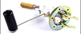
Fuel pump "tens" assembled with FLS
Design and principle of operation
By its design, this controller is a rheostat with nichrome resistance. The adjustable contact of the device moves as a result of the action of a float lever equipped with an additional contact. It should be noted that this contact, when placed in a certain position, can complete a control circuit. As a result, this demonstrates the need to use a reserve volume of gasoline - depending on the design features of the car, the reserve can range from 4 to 6.5 liters of fuel. As mentioned above, warning drivers about a lack of fuel is carried out on the dashboard using arrows.
The fuel level controller on the VAZ 2110 itself is a device that cannot boast of great reliability. After the unit has completed a certain service life, its readings may be incorrect. This is usually due to the main drawback of the device - the track of its contact group is ground off as a result of the friction force of the slider. So if you are interested in the question - why the sensor does not work - then first of all you need to check the track (author - alehtrikus channel).
Messages 9
1 Topic by drummer04 2015-04-14 10:42:54
- drummer04
- New member
- Inactive
- From: St. Petersburg
- Registration: 2015-01-03
- Messages: 78 Thanks : 5
- Car: VAZ 2110 8 valves (2004)
Topic: How to choose the right fuel level sensor for a VAZ 2110?
Hello everyone, the gasoline needle has started to lie, and I want to replace the FLS, but I heard that there are already 8 varieties, and I don’t know which one to buy. They say that you can buy it by the number of the device, I have a device, Automatic Device (AP) with one window Article: 2110-3801010-04, has anyone come across this?
2 Reply from Daniil.Smit 2015-04-14 10:49:18
- Daniel Smith
- New member
- Inactive
- From: Donskoy
- Registration: 2014-12-03
- Messages: 108 Thanks : 6
- Car: VAZ 2111
Re: How to choose the right fuel level sensor for a VAZ 2110?
Take off yours and see what air you have on it and buy the same one, profit
Added: 2015-04-14 11:48:42
It should be written there
Added: 2015-04-14 11:48:59
Added: 2015-04-14 11:49:18
019395.jpeg
45.6 kb, 18 downloads since 2015-04-14
You don't have the permssions to download the attachments of this post.
3 Reply from drummer04 2015-04-14 10:52:01
- drummer04
- New member
- Inactive
- From: St. Petersburg
- Registration: 2015-01-03
- Messages: 78 Thanks : 5
- Car: VAZ 2110 8 valves (2004)
Re: How to choose the right fuel level sensor for a VAZ 2110?
Take off yours and see what air you have on it and buy the same one, profit
Added: 2015-04-14 11:48:42
It should be written there
I thought about it too, but it never changed. and maybe everything there is erased.
Added: 2015-04-14 10:51:02
what is written, where is it written. the picture is only of the FLS
Added: 2015-04-14 10:52:01
aaaaaaaaaaaaaaaa got it all. I didn't notice at first))))
4 Reply from Daniil.Smit 2015-04-14 11:24:40
- Daniel Smith
- New member
- Inactive
- From: Donskoy
- Registration: 2014-12-03
- Messages: 108 Thanks : 6
- Car: VAZ 2111
Re: How to choose the right fuel level sensor for a VAZ 2110?
Yes, I think it is held on by two bolts, you take out the pump and look at the FLS like this
5 Reply from drummer04 2015-04-14 11:29:13
- drummer04
- New member
- Inactive
- From: St. Petersburg
- Registration: 2015-01-03
- Messages: 78 Thanks : 5
- Car: VAZ 2110 8 valves (2004)
Re: How to choose the right fuel level sensor for a VAZ 2110?
yes everything is simple)
6 Reply from Andrey.Lazarev 2016-12-15 23:45:06
- Andrey.Lazarev
- New member
- Inactive
- Registration: 2016-12-15
- Messages: 3 Thanks : 0
- Car: VAZ 21103 1.5 16v
Re: How to choose the right fuel level sensor for a VAZ 2110?
drummer04 , hi, please tell me what blower you installed, I also have a tidy 2110-3801010-04, the arrow jumps either down or up, it’s tortured.
Added: 2016-12-15 23:45:06
I've searched all over Google and there is not a single clear piece of advice on what to install for this or that device.
7 Reply from Dmitriy.Isaev 2016-12-18 15:15:58
- Dmitriy.Isaev
- New member
- Inactive
- Registration: 2016-12-13
- Messages: 3 Thanks : 2
Re: How to choose the right fuel level sensor for a VAZ 2110?
It depends on the type of tidy, if the tidy is from 10 then DUT 1-01, DUT 1-02, DUT 1-03 will do. If the tidy is from Samar (2114,2115) then FLS 2-01.
8 Reply from Andrey.Lazarev 2016-12-19 15:47:56
- Andrey.Lazarev
- New member
- Inactive
- Registration: 2016-12-15
- Messages: 3 Thanks : 0
- Car: VAZ 21103 1.5 16v
Re: How to choose the right fuel level sensor for a VAZ 2110?
Dmitriy.Isaev , thank you
9 Reply from vl_f 2016-12-24 22:11:41 (2016-12-24 22:12:36 edited by vl_f)
- vl_f
- New member
- Inactive
- Registration: 2016-11-22
- Messages: 2 Thanks : 1
- Auto: 2110
Re: How to choose the right fuel level sensor for a VAZ 2110?
I changed the FLS like this: I pulled out the fuel pump and removed the FLS. I looked all over and couldn't find any markings.
I went to the store. The seller turned the FLS in her hands and said: “02.” 02 so 02, especially since there have never been any problems with returning or replacing goods in this store. I installed it on the car - exactly 02: the lower and upper positions of the sensor correspond to the extreme positions of the indicator arrow. Later, out of curiosity, I disassembled the old sensor. It turned out that the “02” marking was hidden under the metal sensor cover. By the way, the old and new sensors differ in appearance (progress does not stand still), the main thing is that the seats match and they work correctly