| Probable Cause | ||
| Code 11 (one long flash, one short flash) | Crankshaft angle sensor or circuit | No reason |
| Code 12 (one long flash, two short flashes) | Starter switch | The starter switch remains constantly on or off |
| Code 13 (one long flash, three short flashes) | Camshaft Angle Sensor | No reason |
| Code 14 (one long flash, four short flashes). | Fuel injector 1 | Poor fuel injector operation |
| Code 15 (one long flash, five short flashes). | Fuel injector 2 | Poor fuel injector operation |
| Code 16 (one long flash, six short flashes) | Fuel injector 3 | Poor fuel injector operation |
| Code 17 (one long flash, seven short flashes) | Fuel injector 4 | Poor fuel injector operation |
| Code 21 (two long flashes, one short flash) | Coolant temperature sensor | The sensor or sensor circuit is malfunctioning |
| Code 22 (two long flashes, two short flashes) | Knock sensor | The electrical circuit of the sensor is broken or shorted |
| Code 23 (two long flashes, three short flashes) | Air flow sensor | The electrical circuit of the sensor is broken or shorted |
| Code 24 (two long flashes, four short flashes) | Air control valve | Valve electrical circuit is open or shorted |
| Code 31 (three long flashes, one short flash) | Throttle position sensor | The electrical circuit of the sensor is broken or shorted |
| Code 32 (three long flashes, two short flashes) | Oxygen sensor | The electrical circuit of the oxygen sensor is broken |
| Code 33 (three long flashes, three short flashes) | Vehicle speed sensor | There is no signal from the vehicle speed sensor |
| Code 35 (three long flashes, five short flashes) | Cleaning solenoid valve | Purge solenoid valve always on or always off |
| Code 41 (four long flashes, one short flash) | Fuel mixture composition | Not optimal fuel mixture ratio |
| Code 42 (four long flashes, two short flashes) | Switching signal | Incorrect switching signal |
| Code 44 (four long flashes, four short flashes) | Damper actuator | Damper actuator valve faulty |
| Code 45 (four long flashes, five short flashes) | Atmospheric sensor | The atmospheric sensor is faulty |
| Code 49 (four long flashes, nine short flashes) | Air flow sensor | Air flow sensor faulty |
| Code 51 (five long flashes, one short flash). | Neutral switch | Neutral switch remains in permanently on position |
| Code 51 (five long flashes, one short flash) | Starter blocker | The lock switch remains in the on position at all times |
| Code 52 (five long flashes, two short flashes) | Position switch | The parking switch remains in the always on position |
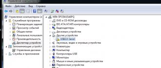
| To determine fault codes in the obd2 self-diagnosis system, you must connect the scanner to the 16-pin diagnostic connector. |
Fault codes in the obd2 self-diagnosis system consist of five digits.
obd2 self diagnostic system fault codes
Diagnostic connector pins for used protocols
The OBDII standard allows for the use of 5 diagnostic protocols. Chevrolet Niva uses 3 of them:
- J1850 PWM. High-speed protocol with a performance of 41.6 Kb/sec. Transmits signals via pins 2, 4, 5, 10, 16.
- J1850 VPW. (The principle) of transmitting signals via pins 2, 4, 5, 16 is the same, but the speed is 10.4 Mb/s.
- ISO 9141-2. The simplest protocol that does not require complex communication microprocesses (unlike the above). Performs pulse transmission using pins 4, 5, 7, 15, 16
Features: The ISO 9141-2 protocol is easy to determine, thanks to pin 7, as well as the exclusion of pin 2 (10) on the Chevy Niva diagnostic connector.
If the system does not have pin 7, the SAE J1850 VPW (Variable Pulse Width Modulation or Pulse Width Modulation) protocol is used. The specified signal transmission protocols function properly via a standard OBD-II J1962 connector cable.
Selecting equipment for diagnosing Niva Chevrolet
The first step when choosing a cable for reading information from an on-board computer is determining the type of connector.
The main difference between OBDI and OBDII (besides the year of manufacture of the vehicle in which it is installed) is the shape of the connector. How to determine what type of pinout is used in a particular car is described in detail above. It is also possible to connect the K-Line connector to the OBD connector on the Niva Chevrolet. In this way, special diagnostic equipment is installed.
To read information from the OCU you will need:
- a scanning device that supports the required type of connections (currently, in addition to traditional equipment operating via a USB cable, there are items that support wi-fi and bluetooth functions);
- laptop;
- adapter (if necessary);
- appropriate software for diagnostics (for the Russian automotive industry, the ScanMaster ELM 2.1 and OpenDiagPro programs are recommended).
Important! The computer must support the same types of information transfer as the adapter. Otherwise, connection will not be possible.
There is a wide range of diagnostic equipment on the modern market. It is divided into the following types:
- "amateur" equipment;
- multi-brand (multifunctional) devices;
- professional equipment.
The last two categories are used for work at service stations and dealerships. For self-diagnosis, it is enough to purchase a simple adapter for beginners based on the ELM327 chip.
Even the most minimally functional equipment is capable of performing all basic tasks (detecting an error, correcting it, transmitting information about the state of the ECU to the PC screen). Such a service in service centers costs up to 1,500 rubles. Purchasing an adapter will save the Niva owner from the need to contact specialists and save money.
Carefully! There are cases when the controller generates an error even though it is fully operational. The reason is the failure of the scanning device itself.
Self-diagnosis
The function involves shutting down the system in which the breakdown occurred, followed by enabling a bypass program. A "Check Engine" light on the dashboard should worry the owner of a Chevrolet Niva. The developers have provided a standard self-diagnosis function. This option is useful in cases where there is a short-term failure in the program, but the machine continues to operate as normal. You can identify an “accident” using self-diagnosis.
ELM327 Niva, specifics
Bluetooth adapters ELM327 When I became concerned about this problem, I attracted an electronics engineer friend of mine, who is very, very meticulous in his profession. He immediately told me the following phrase: China and China are different. I have already tried to convey this idea to the people in an article about rear brake pads. On the current issue, we ordered several samples directly from the FACTORIES and began to slowly mock them, open them and break them. I won't wait long. Only ONE adapter connected normally with the fields and shnives. In the photo, he is in the middle. The rest either did not communicate with the smartphone or did not connect to power at all. Even my branded Konnwey adapter (far right), which sees almost the entire Japanese fleet and half of Europe, did not want to communicate with the fields.
Attention. The main and main function of this Bluetooth adapter ELM327 Niva is only one - to view and erase errors and turn off the “check engine on the panel” light. You can't do anything else on a wireless device. If you want to make friends with the engine more seriously, the tool must be different. A wired USB adapter (possibly with the same ELM327 chip) and a laptop with more serious diagnostic programs.
VAZ-21214 car. Reading codes
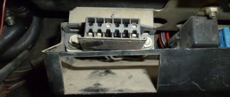
A – contact connected to ground;
B – diagnostic contact for sending a signal to the controller; G – electric fuel pump control contact; M – information output contact (serial data channel) The diagnostic block is used for communication with the controller. It is located under the glove compartment on the right side next to the controller.
Fault codes stored in the controller's memory can be read either with a special diagnostic tool or by counting the number of flashes of the "CHECK ENGINE" lamp.
Issuance of code 12 by the “CHECK ENGINE” indicator lamp
To read the codes with a lamp, you must connect contact “B” of the diagnostic block to ground. The easiest way is to short it to ground by connecting it to contact “A”, which is connected to engine ground.
When contacts “A” and “B” are connected to each other, the key in the ignition switch must be turned to position III (Ignition), but the engine should not run.
Under these conditions, the “CHECK ENGINE” lamp should flash code 12 three times in a row. This should happen in this order: flash, pause (1-2 s), flash, flash - long pause (2-3 s), and so on twice.
Code 12 indicates that the controller diagnostic system is working. If code 12 is not displayed, then there is a problem with the diagnostic system itself.
After code 12 is displayed, the CHECK ENGINE lamp displays fault codes three times, if they exist, or simply continues to display code 12 if there are no fault codes. If more than one fault code is stored in the controller’s memory, they are displayed 3 times each.
Warning Upon completion of the diagnostics, it is allowed to open contacts “A” and “B” of the diagnostic block 15 seconds after turning off the ignition.
Realities
Let's look at the ELM adapter from a purely technical perspective. Its function is simple - it is a translator between the car's ECU and your smartphone or tablet. But translators are different, I declare this responsibly, as a person who speaks German. There are general translators, there is a technical language, there is a diplomatic language, and there is the pinnacle of the art of translation - simultaneous translation. The Chinese wireless version of the ELM adapter represents a high school student who got a C in English and thinks that he knows the language. It would be appropriate to recall an anecdote on this topic. *The Georgian went swimming and began to drown. I either didn’t know the word “help” or forgot it. A man is walking along the shore. The Georgian shouts: uh, darling, help, I’m swimming for the last time. * This is approximately the same information provided by the vast majority of Chinese “Elms”. The Chinese are deceiving consumers twice. First point: a real original ELM 327 chip costs about $20. This doesn't look like 400 rubles. The second point is that all electronics that end up on Ali and other similar sites are shamelessly cut down to cost 400 rubles, or even better, 300, or even better, even cheaper.
ELM327 Niva, specifics
Bluetooth adapters ELM327
When I became concerned about this problem, I attracted an electronics engineer friend of mine, who is very, very meticulous in his profession. He immediately told me the following phrase: China and China are different. I have already tried to convey this idea to the people in an article about rear brake pads. On the current issue, we ordered several samples directly from the FACTORIES and began to slowly mock them, open them and break them. I won't wait long. Only ONE adapter connected normally with the fields and shnives. In the photo, he is in the middle. The rest either did not communicate with the smartphone or did not connect to power at all. Even my branded Konnwey adapter (far right), which sees almost the entire Japanese fleet and half of Europe, did not want to communicate with the fields.
Attention. The main and main function of this Bluetooth adapter ELM327 Niva is only one - to view and erase errors and turn off the “check engine on the panel” light. You can't do anything else on a wireless device. If you want to make friends with the engine more seriously, the tool must be different. A wired USB adapter (possibly with the same ELM327 chip) and a laptop with more serious diagnostic programs.
Reading time
Difficulty of the material:
For the pros - 4 out of 5
The ELM327 diagnostic adapter is widely popular among motorists. It allows you to carry out a quick computer service of electronic modules and track the values of important parameters of the internal combustion engine in real time. The adapter is easy to use and does not require special skills from the owner. The device is actively used for diagnosing not only foreign brands, but also domestic cars.
The ease of working with ELM327 is obvious - just connect the device to the service connector and synchronize it with your computer. The information will be displayed on the display of your PC or smartphone.
In this article you will learn:
Important:
Older models may be equipped with an OBD2 connector, but do not support available ISOs. Such blocks are diagnosed using separate tools.
We diagnose a Chevrolet Niva ourselves - where is the diagnostic connector located?
For self-diagnosis of a Chevrolet Niva, you need an ELM327 and an Android . You can also carry out diagnostics using a wired adapter and a laptop. But in this article we will talk specifically about using the mobile diagnostic option.
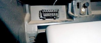
The location of the connector is indicated by an arrow.
Compatibility of VAZ cars with ELM327
The OBD 2 standard, according to which the adapter operates, supports the service of all cars with an electronic injection control system. There are some differences in diagnosing certain types of ECUs, but the general maintenance methods remain the same.
In this section, the user can find accurate information about the compatibility of the ELM327 with the desired vehicle. The table lists the years of production, as well as models. Just select your VAZ type in the list and the system will automatically provide all the information on computer servicing.
Diagnostic modes, OBD protocols for VAZ cars
The OBD standard has five types of information exchange protocols:
- CAN type;
- KWP2000;
- ISO 9141 version 2;
- J1850 VPW and PWM.
The purpose of OBD is to harmonize the various electronic systems of the car and ensure the exchange of information between devices. The standard establishes a number of rules for the transmission of data packets. The exchange speed is individual for each protocol. The ELM327 adapter coordinates the ECU and external devices for reading information. The data is displayed to the user in an accessible form.
The fastest is the CAN bus. The latest Zhiguli models provide for the use of this standard. Other protocols on this family:
- ISO 9141;
- K, L lines;
- K, L lines (extended block 55 pins).
Note: the number of supported diagnostic and interrogation modes of on-board systems depends on the installed protocol. The owner needs to check the year of manufacture and model of the standard control unit before servicing. The more recent the ECU and its firmware, the wider the list of available scanning parameters.
Important:
Some ECUs do not support the full set of functions without the use of a dealer scanner.
Select the car model and year of manufacture to determine which diagnostic modes your car supports through the ELM327 adapter, as well as what protocol the OBD2 port is based on. The data is presented for the following VAZ models and their modifications: 2114, 2107, 2110, 2112, 2109, 2115, 2106, 2108 and others.
Note:
(1) — The numbers between brackets (x3) correspond to the number of vehicles of the same type
(2) - DIN horsepower (multiplied by 0.736 for kW power)
(3) - PID is only supported for the primary oxygen sensor (#1)
- Mode X Column: A vehicle showing 00000000 in a mode means that the corresponding PID is not active and that as a result the mode is maintained but does not respond to any requests. None of the vehicles described below support Mode 8.
- Energy column: fuel type, Die for diesel, Pet for gasoline, Hyb for hybrid
- The vehicles on this list are classified alphabetically by make, model, then in order of increasing horsepower.
Mode 1
This mode returns common values for some sensors, such as:
- engine speed;
- vehicle speed;
- engine temperature (air, coolant);
- information about oxygen sensors and air-fuel mixture.
Mode 2
This mode provides a freeze frame (or instantaneous) failure data. When the ECM detects a malfunction, it records sensor data at the specific point in time when the malfunction occurs.
Mode 3
This mode displays stored diagnostic trouble codes. These fault codes are standard for all car brands and are divided into 4 categories:
P0xxx: for standard transmission related faults (engine and transmission) C0xxx: for standard chassis faults B0xxx: for standard body faults U0xxx: for standard communication network faults
More detailed information and definitions of common trouble codes are available on the OBD Common Trouble Codes page.
Mode 4
This mode is used to clear stored trouble codes and turn off the engine malfunction indicator.
Note: There is generally no need to repair a problem that has not been diagnosed or corrected. The MIL will illuminate again during the next driving cycle.
Mode 5
This mode provides the results of self-diagnosis performed on the oxygen/lamda sensors. This mainly applies only to gasoline vehicles. For new ECUs using CAN, this mode is no longer used. Mode 6 replaces features that were available in Mode 5.
Mode 6
This mode provides self-diagnosis results performed on systems that are not subject to constant monitoring.
Mode 7
This mode produces unconfirmed fault codes. After repair, it is very useful to check that the fault code does not appear again, without having to perform a lengthy test run. The codes used are identical to those in mode 3.
Mode 8
This mode provides self-diagnosis results on other systems. It is unlikely to be used in Europe.
Mode 9
This mode gives vehicle information such as:
- VIN (vehicle identification number)
- calibration values
Mode 10 (or Mode A)
This mode gives permanent error codes. The codes used are identical to those in modes 3 and 7. Unlike modes 3 and 7, these codes cannot be cleared using mode 4. Only a few road cycles without the problem occurring can clear the fault.
Electrical diagram of the VAZ 21214 car
Another modern modification of the domestic NIVA is the VAZ-21214. A high-quality color wiring diagram contains wiring indicating all components and elements - headlights, fans, switches and various sensors. The car's fuse and relay box is provided separately, with a detailed explanation of the purpose of each fuse link. All diagrams are taken from open sources and are provided for your viewing completely free of charge. By clicking on the picture below, the VAZ-21214 (NIVA) electrical equipment diagram will open in high resolution.
Symbols on the diagram
1. Left front light. 2. Headlights. 3. Coolant temperature sensor. 4. Sound signal. 5. Throttle position sensor. 6. Mass air flow sensor. 7. Electromagnetic valve for adsorber purge. 8. Injectors. 9. Right front lamp. 10. Side direction indicators. 11. Rechargeable battery. 12. Electric heater motor. 13. Additional resistor for the heater motor. 14. Differential lock warning lamp switch.15. Windshield wiper relay. 16. Starter 21214. 17.
Windshield wiper motor.18. Generator VAZ-21214. 19. Windshield washer motor.20. Ignition module. 21. Spark plugs.22. Controller. 23. Idle speed control. 24. APS status indicator. 25. Temperature indicator sensor.26. Oil pressure warning light sensor. 27. Socket for portable lamp(*). 28. Brake fluid level warning lamp switch. 29. Diagnostic block. 30. Relay for turning on the heated rear window. 31. Headlight high beam relay. 32.
Relay for low beam headlights. 33. Electric fuel pump with fuel level sensor. 34. Starter activation relay. 35. Additional fuse block.36. Main fuse block. 37. Relay-breaker for direction indicators and hazard warning lights. 38. Reversing light switch. 39. Brake light switch. 40. Cigarette lighter VAZ-21214. 41. External lighting switch.42. Illumination lamps for heater control levers. 43. Rear fog light switch. 44. Rear window heating switch. 45.
Heater motor switch. 46. Rear window wiper and washer switch. 47. Hazard switch. 48. Ignition switch. 49. Instrument lighting switch. 50. Windshield wiper switch. 51. Windshield washer switch. 52. Horn switch. 53. Turn signal switch. 54. Headlight switch. 55. Electric fuel pump relay. 56. Vehicle speed sensor. 57. Lamp switches located in the door pillars. 58. Interior lamps.
59. Rear window washer motor. 60. Instrument cluster. 61. Parking brake warning lamp switch. 62. Main relay. 63. Tail lights. 64. License plate lights. 65. Rear window wiper motor. 66. Rear window heating element. 67. Crankshaft position sensor. 68. Knock sensor. 69. VAZ oxygen sensor. 70. Electric fan relay. 71. Electric fans. 72. Injection system fuse block. 73. To the interior lamp. 74.
To the dome light switch in the driver's door. 75. APS control unit.
ELECTRICAL CONNECTION DIAGRAM FOR FRONT WIRING HARNESS 21214-3724010-44
IGNITION SYSTEM WIRING HARNESS CONNECTION DIAGRAM 21214-3724026-44
INSTRUMENT PANEL WIRING HARNESS CONNECTION DIAGRAM 21214-3724030-44
REAR HARNESS DIAGRAM 21214-3724210-44
Auto fuse box
Recently, the rear fog lamp switch has a more complex device than shown in the diagram. An additional relay may be used. New VAZ-21214 models are equipped with windshield wipers and headlight washers. Their connection diagram is similar to the VAZ-21213.
CAR ELECTRONICS REPAIR
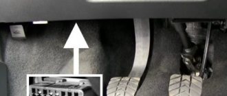
Where is the diagnostic connector located on a Chevrolet Niva?
The classic location of the diagnostic connector block in most cars is behind the steering wheel near the ignition switch. Chevy Niva is no exception. The OBD type pinout is used. On-board diagnostics of the first generation was developed back in 1991 with the purpose of reading information on the state of the ECU (electronic control unit). This system is responsible for all engine functions.
The first copies of Niva Chevrolet used a 12-pin OBD1 connector. Since 2002, it was changed to 16-pin OBD2. To select the correct diagnostic equipment for the on-board computer, you need to find out in advance what type of pinout is in a particular Chevrolet Niva.
Additional Information
On some Chevrolet Niva models there is a 12-pin block, this is due to the fact that these models are equipped with other control units of older models. Modern car scanners are mainly based on the OBD2 connector, so to connect to 12 PINs you will need a special adapter purchased or made independently.
The correct connection diagram for a 12 PIN block with a 16 PIN adapter
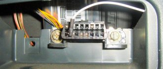
Diagnostic connector Niva 21214 where is it located?
6.2.2. Self-diagnostic system (OBD) and codes
| GENERAL INFORMATION |
Digital Voltmeter
Scanner
Warning
On models from 1990 to 1994, the obd1 self-diagnosis system is installed, and since 1995, the obd2 self-diagnosis system is installed.
To determine fault codes in the obd1 system, you simply need to disconnect the test connector located under the instrument panel. But to determine fault codes in the obd2 system, you need to use a special device to view fault codes. To diagnose the exhaust gas emission reduction system and control engine operation, it is advisable to use a digital voltmeter, which has a high input resistance and does not affect the operation of the circuit being tested (see Fig. Digital voltmeter).
To determine fault codes and analyze engine control systems, it is necessary to use special scanners (see Fig. Scanner).
The ecm contains a built-in self-diagnosis system that detects and classifies faults in electrical circuits. When the ECM module detects a malfunction, the check engine light comes on, the malfunction is identified, and a fault code is recorded and stored in memory.
There are four methods for self-diagnosis of engine malfunction. The check engine warning light comes on if there is a fault in the u-mode.
most user friendly.
Memory reading method.
Designed for the maintenance department to check stored fault codes.
Used to check faulty parts.
Cleaning method.
Designed to delete recorded fault codes.
| A digital voltmeter is used to diagnose the emission control system and control engine operation. | The scanner is used to determine fault codes and analyze engine management systems. |
| EXECUTION ORDER |
| 2. Turn on the ignition without starting the engine and check that the “check engine” lamp on the instrument cluster is on. | |
| 3. Observe the “check engine” light, which will highlight fault codes stored in the computer’s memory. If there are no fault codes, the check engine light will not light up. If the check engine light flickers, it means that the fault method test connector is not disconnected. | |
| 4. Observe the check engine light and identify any fault codes. The first digit of the fault code is displayed with long flashes, and the second digit of the fault code is displayed with short flashes. For example, 4 long flashes represents the number 4, and two short flashes represent the number 2, that is, fault code 42. |
Niva sensors
As you know, the first Russian SUV Niva was born back in the days of the Soviet Union. At that time, in the USSR they did not even think about an electronic engine control system; the entire process of operation of the internal combustion engine was mechanical. The engine was supplied with fuel through a carburetor. At present, the Niva still continues to be produced, but with its ancestors, the modern Niva has only the body left and it has undergone minor modifications.
The carburetor was replaced with an injector, the interior was changed and the appearance of the car was transformed, but still the Niva remained Niva. The legendary Niva cross-country ability did not deteriorate after these modifications, but became much more comfortable.
In this article we will talk about the sensors of the engine control system in the injection Niva, namely, it describes in detail each of the sensors, where it is located and what function it is responsible for, as well as the signs of sensor malfunction are described in detail.
Electronic engine control unit (ECU)
An ECU is a kind of computer in a car; it is in this device that the entire operation of the internal combustion engine is corrected. All sensors that are installed in the car transmit readings specifically to this unit, and based on the readings, it makes changes to the operation of the engine, which affects both the engine speed and its consumption.
Symptoms of ECU malfunction:
There can be a huge number of signs of malfunction of this unit, because signs of failure of one sensor may even indicate failure of the unit.
Mass air flow sensor (MAF)
This sensor is located near the Niva air filter box. Air flows through this sensor, which is necessary to form the air-fuel mixture. The sensor records the amount of air passing through it and sends signals to the electronic engine control unit (ECU).
Signs of a DMRV malfunction:
- Loss of vehicle dynamics;
- Increased fuel consumption;
- Unstable idling (speeds fluctuate);
- Difficulty starting the engine when the engine is warm;
The Niva DPKV is installed in a special hole in the oil pump drive cover. This sensor is responsible for setting the ignition timing.
The sensor takes readings from the crankshaft pulley, which has teeth and in one of the places there is “caries”, that is, several pulley teeth are missing. It is “caries” that the DPKV understands in what position the crankshaft is.
The sensor itself resembles an inductive coil, which generates impulses when the crankshaft rotates and transmits them to the computer.
If the sensors fail, the car will not start.
Signs of DPKV malfunction:
- The car does not start;
- The car stalls spontaneously;
- Uneven operation of the internal combustion engine;
DTOZH on Niva is installed in the cylinder head outlet pipe. The coolant temperature sensor is a fairly simple element in its design. The sensor is based on a thermistor, which changes its resistance as the temperature changes.
One of the functions of the sensor is to start the electric engine cooling fans when the coolant temperature threshold is reached. The sensor is also responsible for starting the engine in cold weather; according to the coolant temperature readings, the electronic control unit forms the fuel mixture necessary for more proper warming up of the car engine. This can be replaced by the presence of high warm-up speeds at the moment of starting the internal combustion engine.
Signs of DTOZh malfunction:
- Cooling fans do not work;
- No warm-up speeds;
- Difficulty starting the internal combustion engine;
- Increased fuel consumption;
The TPS is installed on the throttle itself and is a potentiometer. This sensor reads readings from the throttle position and transmits them to the ECU. The damper opens access to air, thereby increasing engine speed. When the damper opens, the sensor sends a signal to the control unit to increase the fuel supply, which is necessary to form a working air-fuel mixture.
The sensor that most often fails is an unreliable element of the system. Subsequently, they abandoned it and switched to an electronic throttle.
Signs of a malfunction of the TPS:
- High speed at start-up;
- Jumps in engine speed;
- Increased fuel consumption;
- Not smooth idle;
The knock sensor is installed on the right side of the vehicle's cylinder block. A DD is needed to catch detonations in the engine and adjust the fuel mixture. The sensor itself is made on the principle of a piezoelectric element and, in the presence of vibrations in the engine, transmits impulses to the ECU, which in turn adjusts the fuel mixture.
Signs of DD malfunction:
- Increased fuel consumption;
- Uneven operation at idle (increased vibrations);
- Jerks when the car moves;
The oil pressure sensor is located on the right side of the cylinder block and is screwed into the oil line fitting. This sensor is necessary to monitor the oil pressure in the engine. As you know, operating a car with low oil pressure in the internal combustion engine can damage it. When the oil pressure in the internal combustion engine decreases, the sensor closes the contact and sends a signal to the Niva instrument panel, lighting up the oil pressure indicator in the form of a red oil can.
Signs of DDM malfunction:
- Constant lighting of the oil pressure lamp;
- Oil leak from the sensor junction;
This sensor is located, just like the TPS, on the Niva’s throttle valve. The essence of the sensor's operation is to open and close the channels through which air flows to operate at idle speed. The IAC is involved in the operation of the internal combustion engine only at idle; when the speed increases, the regulator is switched off. IAC is a kind of DC motor with worm gear. Quite often the sensor fails. Subsequently, this sensor was abandoned in favor of an electronic throttle.
Signs of IAC malfunction:
- Lack of XX speed (engine stalls);
- Increased speed at idle;
- Increased fuel consumption;
The phase sensor, also known as the camshaft position sensor, is installed in the cylinder head plug. Designed for phased fuel injection. Reads readings from the camshaft and transmits them to the computer; these readings are necessary for accurate distribution of the fuel mixture between the cylinders.
Signs of DF malfunction:
- Increased fuel consumption;
- Increased engine vibrations;
The brake pedal sensor is installed on the pedal assembly under the Niva's steering column. In cars without the E-GAZ system, it is only responsible for turning the brake lights on and off. In cars that have an electronic throttle and therefore an electronic gas pedal, this sensor affects the operation of the pedal. If the brake sensor breaks down, the gas pedal stops working.
Signs of malfunction:
- The gas pedal does not work;
- Jerking when moving at a constant speed;
- Loss of power and vehicle dynamics;
The speed sensor of the Niva car is installed in the transfer case. The function of the sensor is to transmit vehicle speed readings. The sensor also forms the fuel mixture; when the car is moving at neutral speed, you can notice that the speed is slightly higher than when the car is running at XX while standing still. Increased speed when driving is necessary to avoid dips when turning on the speed and sharp acceleration.
OBD 1 pinout
To correct the operation of electronic systems, OBD equipment was invented. The first generation pinout has a rectangular shape with 12 pins.
Each of the elements of the nest has its own purpose:
- pin A transmits mass information;
- B corresponds to the diagnostic L-line;
- D—CO potentiometer;
- contact G is responsible for the fuel pump control functions;
- H—food;
- M - K-Line diagnostics.
At the bottom of the pinout there is a “Key”, which is responsible for maintaining the correct design of the equipment. This element is designed to ensure the correct orientation of the plug and connector in the car.
Car brands and years of manufacture
Any injection model before 2002 has an OBD1 pinout. When determining the type of diagnostic connector for 2002 cars, it is worth considering that some may already use OBD2. They can be easily distinguished by their “rosette” shape.
OBD 2 pinout
The 12-pin OBD1 in the Chevrolet Niva has been replaced by OBD2. This is due to the introduction of new standards in Europe since 2001. This solution has significantly expanded the possibilities of car diagnostics.
The first copies of the equipment showed general error information. Using OBD2, the car owner can independently obtain complete information on the state of the ECU by using a scanning device or adapter. 16-pin connector. Its shape has changed: now it is a trapezoid with a narrowing downwards.
The plug contacts are responsible for the following diagnostic elements:
- pin 2 - bus+ (via J1850);
- 4 — body grounding;
- 5 - signal grounding;
- 6 - CAN-High line (via J-2284 protocol);
- 7 - K-Line;
- 10 — bus- (via J1850);
- 14 - CAN-Low line (via J-2284 protocol);
- 15 — L-line;
- 16 - battery powered.
Car brands and years of manufacture
OBDII has been used in cars since 1996 in the USA. In Europe, standards changed in 2001. In the Chevrolet Niva, new diagnostic connectors first appeared in the 2002-2019 models. These cars work with control systems BOSCH MP7.0 Euro-3, BOSCH M7.9.7, January-7.2, January-7.3.
Access and location
The location remains unchanged: at the ignition switch. OBDII is partially hidden behind the steering wheel cover.
6.2.2 Self-diagnosis (OBD) system and codes
6.2.2. Self-diagnostic system (OBD) and codes
| GENERAL INFORMATION |
Digital voltmeter
| A digital voltmeter is used to diagnose the emission control system and control engine operation. |
Scanner
| The scanner is used to determine fault codes and analyze engine management systems. |
Warning: On models from 1990 to 1994, the obd1 self-diagnosis system is installed, and since 1995, the obd2 self-diagnosis system is installed.
To determine fault codes in the obd1 system, you simply need to disconnect the test connector located under the instrument panel. But to determine fault codes in the obd2 system, you need to use a special device to view fault codes. To diagnose the exhaust gas emission reduction system and control engine operation, it is advisable to use a digital voltmeter, which has a high input resistance and does not affect the operation of the circuit being tested (see Fig. Digital voltmeter).
To determine fault codes and analyze engine control systems, it is necessary to use special scanners (see Fig. Scanner).
The ecm contains a built-in self-diagnosis system that detects and classifies faults in electrical circuits. When the ECM module detects a malfunction, the check engine light comes on, the malfunction is identified, and a fault code is recorded and stored in memory.
There are four methods for self-diagnosis of engine malfunction. The check engine warning light comes on if there is a fault in the u-mode.
most user friendly.
Memory reading method.
Designed for the maintenance department to check stored fault codes.
Used to check faulty parts.
Cleaning method.
Designed to delete recorded fault codes.
| EXECUTION ORDER | ||
| Probable Cause | ||
| Code 11 (one long flash, one short flash) | Crankshaft angle sensor or circuit | No reason |
| Code 12 (one long flash, two short flashes) | Starter switch | The starter switch remains constantly on or off |
| Code 13 (one long flash, three short flashes) | Camshaft Angle Sensor | No reason |
| Code 14 (one long flash, four short flashes). | Fuel injector 1 | Poor fuel injector operation |
| Code 15 (one long flash, five short flashes). | Fuel injector 2 | Poor fuel injector operation |
| Code 16 (one long flash, six short flashes) | Fuel injector 3 | Poor fuel injector operation |
| Code 17 (one long flash, seven short flashes) | Fuel injector 4 | Poor fuel injector operation |
| Code 21 (two long flashes, one short flash) | Coolant temperature sensor | The sensor or sensor circuit is malfunctioning |
| Code 22 (two long flashes, two short flashes) | Knock sensor | The electrical circuit of the sensor is broken or shorted |
| Code 23 (two long flashes, three short flashes) | Air flow sensor | The electrical circuit of the sensor is broken or shorted |
| Code 24 (two long flashes, four short flashes) | Air control valve | Valve electrical circuit is open or shorted |
| Code 31 (three long flashes, one short flash) | Throttle position sensor | The electrical circuit of the sensor is broken or shorted |
| Code 32 (three long flashes, two short flashes) | Oxygen sensor | The electrical circuit of the oxygen sensor is broken |
| Code 33 (three long flashes, three short flashes) | Vehicle speed sensor | There is no signal from the vehicle speed sensor |
| Code 35 (three long flashes, five short flashes) | Cleaning solenoid valve | Purge solenoid valve always on or always off |
| Code 41 (four long flashes, one short flash) | Fuel mixture composition | Not optimal fuel mixture ratio |
| Code 42 (four long flashes, two short flashes) | Switching signal | Incorrect switching signal |
| Code 44 (four long flashes, four short flashes) | Damper actuator | Damper actuator valve faulty |
| Code 45 (four long flashes, five short flashes) | Atmospheric sensor | The atmospheric sensor is faulty |
| Code 49 (four long flashes, nine short flashes) | Air flow sensor | Air flow sensor faulty |
| Code 51 (five long flashes, one short flash). | Neutral switch | Neutral switch remains in permanently on position |
| Code 51 (five long flashes, one short flash) | Starter blocker | The lock switch remains in the on position at all times |
| Code 52 (five long flashes, two short flashes) | Position switch | The parking switch remains in the always on position |
| To determine fault codes in the obd2 self-diagnosis system, you must connect the scanner to the 16-pin diagnostic connector. |
Fault codes in the obd2 self-diagnosis system consist of five digits.
obd2 self diagnostic system fault codes
Electrical diagram of Lada 4×4 (VAZ 21213, 21214)
05 November 2015 Lada.Online 166 555
During the operation of the car, problems may arise that can only be solved after studying the electrical circuits. The article presents detailed wiring diagrams for the Lada 4×4 SUV (VAZ 2121), which will help you not only repair the car, but will also be useful when installing additional electrical equipment, for example, a car alarm, DVR and other accessories..
Electrical diagram of VAZ-21213
1 — headlights; 2 — side direction indicators; 3 — electric motor for windshield washer; 4 — headlight washer motor*; 5 - switch; 6 - battery; 7 - starter; 8 - generator; 9 — headlights; 10 — gearmotors for headlight cleaners*; 11 — sound signal; 12 — spark plugs; 13 — carburetor limit switch; 14 — carburetor solenoid valve; 15 — ignition coil; 16 — windshield wiper gearmotor; 17 — carburetor solenoid valve control unit; 18 — ignition distributor sensor; 19 — coolant temperature indicator sensor; 20-oil pressure warning lamp sensor; 21 — plug socket for a portable lamp**; 22 — brake fluid level warning lamp sensor; 23 — windshield wiper relay; 24 — relay for turning on the rear fog light***; 25 — relay for turning on the heated rear window; 26 — relay for turning on headlight cleaners and washer*; 27 — relay for turning on low beam headlights; 28 — relay for turning on the high beam headlights; 29 — ignition relay; 30 — starter activation relay; 31 — relay-breaker for alarm and direction indicators; 32 — heater electric motor; 33 — additional resistor of the heater electric motor; 34 — backlight lamps for heater control levers; 35 — external lighting switch; 36 — main fuse block; 37 — additional fuse block; 38 — reverse light switch; 39 — brake light switch; 40 — instrument lighting regulator; 41 — ignition switch; 42 — three-lever switch; 43 — alarm switch; 44 — tailgate glass cleaner and washer switch*; 45 — heater motor switch; 46 — switch for heating the rear door glass; 47 — rear fog light switch; 48 — lamp switches located in the door pillars; 49 — interior lamps; 50 - cigarette lighter; 51 — switch for the warning lamp for covering the carburetor air damper; 52 — control lamp for covering the carburetor air damper; 53 - switch for differential lock warning lamp; 54 — parking brake warning lamp switch; 55 — sensor for level indicator and fuel reserve; 56 — instrument cluster; 57 — tailgate glass washer motor; 58 — rear lights; 59 — block for connecting additional brake lights; 60 — blocks for connecting side marker indicators; 61 — pads for connecting to the heated glass element of the tailgate; 62 — license plate lights; 63 — gear motor for tailgate glass cleaner.
The order of conditional numbering of plugs in the blocks : a - windshield wipers, headlights and tailgate glass, windshield wiper relay breaker; b — ignition distributor sensor; c — relay-interrupter for alarm and direction indicators; g - switch; d — three-lever switch; e — alarm switch; g — relay for turning on the rear fog light; h — rear lights (numbering of terminals in order from top to bottom); and — instrument clusters.
In the instrument panel wiring harness, the second ends of the white wires are brought together to one point, which is connected to the instrument lighting control. The second ends of the black wires are also brought together to a point connected to ground. The second ends of the yellow wires with a blue stripe are brought together to a point connected to terminal “A” of the main fuse block. And the second ends of the orange wires are also brought together to a point connected to terminal “B” of the main fuse block.
* Installed on parts of manufactured cars; **not installed since 2000; *** installed since 2001. Previously, the rear fog light was switched on directly by switch 47, powered by fuse 3 of the additional fuse box.
Electrical diagram of VAZ-2121
1 — headlights; 2 — side direction indicators; 3 — headlight washer motor*; 4 - voltage regulator; 5 — battery charge warning lamp relay; 6 - battery; 7 - starter; 8 - generator; 9 — headlights; 10 — gearmotors for headlight cleaners*; 11 — sound signals; 12-spark plugs; 13 — carburetor solenoid valve; 14 — ignition coil; 15 — windshield wiper gearmotor; 16 — coolant temperature indicator sensor; 17 — ignition distributor; 18 — windshield washer electric motor; 19 — oil pressure indicator sensor; 20 — oil pressure warning lamp sensor; 21 — brake fluid level warning lamp sensor; 22 — plug socket for a portable lamp; 23 — relay for turning on headlight cleaners and washer*; 24 — relay for turning on low beam headlights; 25 — relay for turning on the high beam headlights; 26 — windshield wiper relay; 27 — additional fuse block; 28 — main fuse block; 29 — additional resistor of the heater electric motor; 30 — reverse light switch; 31 — brake light switch; 32 — heater electric motor; 33 — relay-interrupter for alarm and direction indicators; 34 — parking brake warning lamp switch; 35 — alarm switch**; 36 — cigarette lighter; 37 — switch for cleaners and headlight washers*; 38 — heater motor switch; 39- external lighting switch; 40 — three-lever switch; 41 — ignition switch; 42 — instrument lighting switch; 43 — lamp switches located in the door pillars; 44 — interior lamps; 45 — oil pressure gauge with insufficient pressure warning lamp; 46 — fuel level indicator with reserve warning lamp; 47 — tachometer; 48 — parking brake warning lamp; 49 — battery charge indicator lamp; 50 — control lamp for the carburetor air damper; 51 — side light indicator lamp; 52 — turn signal indicator lamp; 53 — control lamp for high beam headlights; 54 — speedometer; 55 — carburetor air damper warning lamp switch; 56 — relay-interrupter for the parking brake warning lamp; 57 — coolant temperature indicator; 58 — brake fluid level warning lamp; 59 — differential lock warning lamp; 60 - switch for differential lock warning lamp; 61 — rear lights; 62 — license plate lights; 63-sensor for level indicator and fuel reserve.
Diagnostic connector pins for used protocols
The OBDII standard allows for the use of 5 diagnostic protocols. Chevrolet Niva uses 3 of them:
- J1850 PWM. High-speed protocol with a performance of 41.6 Kb/sec. Transmits signals via pins 2, 4, 5, 10, 16.
- J1850 VPW. (The principle) of transmitting signals via pins 2, 4, 5, 16 is the same, but the speed is 10.4 Mb/s.
- ISO 9141-2. The simplest protocol that does not require complex communication microprocesses (unlike the above). Performs pulse transmission using pins 4, 5, 7, 15, 16
Features: The ISO 9141-2 protocol is easy to determine, thanks to pin 7, as well as the exclusion of pin 2 (10) on the Chevy Niva diagnostic connector.
If the system does not have pin 7, the SAE J1850 VPW (Variable Pulse Width Modulation or Pulse Width Modulation) protocol is used. The specified signal transmission protocols function properly via a standard OBD-II J1962 connector cable.
What is needed for diagnosis
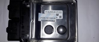
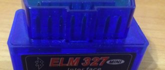
Adapter ELM327 version 1.5 bluetooth connection.
It is advisable to buy an adapter that costs at least 500 rubles. Since cheaper versions come with a 1.2 chip, which cannot always connect to the Chevrolet Niva. It all depends on the version of the ECU.
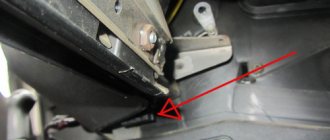
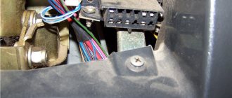
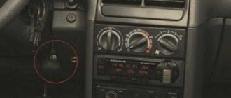
Where is the diagnostic connector located?
Unlike other AVTOVAZ models, the diagnostic connector is located in a convenient location - next to the ignition key. Check out the photo below.
The arrow marks the connector in which the adapter is already installed.
Selecting equipment for diagnosing Niva Chevrolet
The first step when choosing a cable for reading information from an on-board computer is determining the type of connector.
The main difference between OBDI and OBDII (besides the year of manufacture of the vehicle in which it is installed) is the shape of the connector. How to determine what type of pinout is used in a particular car is described in detail above. It is also possible to connect the K-Line connector to the OBD connector on the Niva Chevrolet. In this way, special diagnostic equipment is installed.
To read information from the OCU you will need:
- a scanning device that supports the required type of connections (currently, in addition to traditional equipment operating via a USB cable, there are items that support wi-fi and bluetooth functions);
- laptop;
- adapter (if necessary);
- appropriate software for diagnostics (for the Russian automotive industry, the ScanMaster ELM 2.1 and OpenDiagPro programs are recommended).
Important! The computer must support the same types of information transfer as the adapter. Otherwise, connection will not be possible.
There is a wide range of diagnostic equipment on the modern market. It is divided into the following types:
- "amateur" equipment;
- multi-brand (multifunctional) devices;
- professional equipment.
The last two categories are used for work at service stations and dealerships. For self-diagnosis, it is enough to purchase a simple adapter for beginners based on the ELM327 chip.
Even the most minimally functional equipment is capable of performing all basic tasks (detecting an error, correcting it, transmitting information about the state of the ECU to the PC screen). Such a service in service centers costs up to 1,500 rubles. Purchasing an adapter will save the Niva owner from the need to contact specialists and save money.
Carefully! There are cases when the controller generates an error even though it is fully operational. The reason is the failure of the scanning device itself.
Self-diagnosis
The function involves shutting down the system in which the breakdown occurred, followed by enabling a bypass program. A "Check Engine" light on the dashboard should worry the owner of a Chevrolet Niva. The developers have provided a standard self-diagnosis function. This option is useful in cases where there is a short-term failure in the program, but the machine continues to operate as normal. You can identify an “accident” using self-diagnosis.
Diagnostics of Niva Chevrolet
The Chevrolet Niva diagnostic connector helps you obtain information about how most units work, into which special equipment is connected via Bluetooth or a cable. Therefore, if you want to conduct independent diagnostics, it is important to know where it is.
The connector in the Niva is located under the steering wheel on the right side, and the pinout itself is under the dashboard on the driver’s side. To check the on-board computer, you need to use special equipment that transmits all the necessary information to the laptop. Data transfer is carried out using a COM port into which a K-LINE type connector is installed.
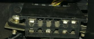
When connecting, errors may appear on the laptop screen. At this moment, there is no need to worry, since the appearance of such messages may be due to a lack of communication with the device itself. You should also check whether the standard anti-theft system is installed; if so, check the adapter itself. If there is a standard location, then it is connected to the diagnostic line between the ECU and the immobilizer. And if it is missing, a plug is installed in its place. To restore communication between the contacts, a jumper is installed, as shown in the picture below:
Depending on the year of manufacture of the model, the connectors may differ from each other.
- 1 Self-diagnosis
- 2 Check engine error
- 3 Chip tuning
- 4 Summary
Check engine error
If a check light comes on on a Niva Chevrolet car, this warns that there are malfunctions associated with the operation of the engine. The light comes on at the moment when the engine begins to detect a failure or error and writes a specific code into its memory.
Let's look at the main reasons why this warning may appear:
- The air/fuel mixture is incorrect. This problem is eliminated by filling the tank with higher quality gasoline.
- Low engine oil level
- Engine overheated
- There are problems with the ignition system, which may be due to a faulty spark plug or ignition coil
- The power system is faulty. It is possible that fuel injection into one of the cylinders has stopped.
- Lambda probe faulty
- A separate sensor in the ECM system has failed
We can conclude that in some cases, when the engine starts and the check light is on, this may indicate that the engine is operating in emergency mode and the problem is not very critical. If the engine starts and stalls, then this is most likely a problem with the fuel supply or the crankshaft sensor has failed.
In any case, it is better not to use the car until you find out the exact reason.
Chip tuning
Some drivers do chip tuning of the Chevrolet Niva in order to increase engine power. The essence of this procedure is to remove the established restrictions by adjusting the optimal factory settings in the electronic control unit. This procedure helps to extract the additional performance inherent in the motor.
The whole process can be divided into several stages:
- Reading the necessary data from the electronic control unit
- Making the necessary adjustments
- Updating and recording new data
The main advantage of this procedure is:
- Engine power increases
- Speed limit removed
- You can change the fuel type
- All factory settings can be returned at any time
ELM327 Niva, specifics
Bluetooth adapters ELM327 When I became concerned about this problem, I attracted an electronics engineer friend of mine, who is very, very meticulous in his profession. He immediately told me the following phrase: China and China are different. I have already tried to convey this idea to the people in an article about rear brake pads. On the current issue, we ordered several samples directly from the FACTORIES and began to slowly mock them, open them and break them. I won't wait long. Only ONE adapter connected normally with the fields and shnives. In the photo, he is in the middle. The rest either did not communicate with the smartphone or did not connect to power at all. Even my branded Konnwey adapter (far right), which sees almost the entire Japanese fleet and half of Europe, did not want to communicate with the fields.
Attention. The main and main function of this Bluetooth adapter ELM327 Niva is only one - to view and erase errors and turn off the “check engine on the panel” light. You can't do anything else on a wireless device. If you want to make friends with the engine more seriously, the tool must be different. A wired USB adapter (possibly with the same ELM327 chip) and a laptop with more serious diagnostic programs.
VAZ cars have a fault diagnostic system that allows you to read and decipher error codes. Most VAZ-2110 cars have an old type “January-4” controller installed. The activation of “CHECK ENGINE” is considered a malfunction detection signal. Troubleshooting in such a controller is simple - error codes are calculated starting from the number 12 and ending with 61. For more modern VAZ models, ELM-327 electronic adapters with the OBD-II program are suitable.
Where is the diagnostic connector located?
On different cars of the VAZ family, the socket is located in different parts of the car. Let's look at a few models as an example:
- on the VAZ-2112, as well as on the 2110, as well as 2111, the socket is located to the right of the driver’s seat, immediately under the column;
- on models 2108\, 2109 and 21099, the socket you need is located under the glove compartment, on a special shelf;
- on cars with a europanel it can be found in the center of the console, near the cigarette lighter. A special decorative cover is used to disguise it;
- on Lada Kalina cars the connector is near the gear shift lever, it is also hidden under a special cover;
- On a Lada Priora, look right behind the glove compartment, on the wall.
How to diagnose a car
- Connect contact “B”, which has the diagnostic block and “ground”;
- Turn the ignition key to the third position, do not start the car;
- First, the “CHECK ENGINE” lamp displays code 12 with 3 flashes. It shows that the diagnostic programs are working. On the VAZ 2110 this happens in this order: the lamp blinks briefly 1 time (which should be considered the designation of number 1). After a pause lasting at least 2 seconds, it flashes 2 times in a row (two). So we got the number two. And this is repeated 3 times so that the driver understands these signs;
- After the diagnostic program has declared its serviceability, it will begin to display error codes, if there are any, of course. In the same way - flashes and pauses.
Diagnostic algorithm
On your phone you need to download and install the program: “ OpenDiag ”. It's free.
Error message.
It is emphasized what to press.
Select "errors".
Deciphering error codes
The first character is a letter and indicates a fault block:
- B - body;
- C - suspension;
- P — engine (ECM, gearbox);
- U - data exchange bus.
The second character is a number, code type:
- 0 — SAE (standard);
- 1.2 - OEM (factory);
- 3 - reserved.
The third character is a number, system:
- 1, 2 - fuel system;
- 3 - ignition system;
- 4 — reduction of exhaust gas toxicity;
- 5 - idle;
- 6 - ECU or its circuits;
- 7, 8 — transmission (automatic transmission).
The fourth and fifth characters are numbers, the error code itself.
The ECM controller of the VAZ-21214 injection engine on the Lada 4x4 car has a built-in diagnostic system. It can recognize problems with the system, warning the driver about them through the “CHECK ENGINE” indicator. In addition, the ECM diagnostic system stores diagnostic error codes that indicate areas of trouble to assist technicians in making repairs.