Carrying out computer diagnostics of car faults has long been available not only for foreign cars, but also for many domestic VAZ cars with an injector.
This opportunity appeared thanks to the equipping of VAZ cars with electronic control units (ECU). Equipping a car with various electronic sensors makes it possible to diagnose a breakdown using computer programs, by connecting through a special OBD VAZ connector (OBD VAZ).
Next, we will look at what an OBD connector is, where the specified diagnostic connector is located, and also what the pinout of the diagnostic connector is, using the example of a VAZ 2110.
Diagnostics via OBD 2
The verification procedure is carried out as follows:
- Depending on the vehicle, the diagnostic process can be carried out with the ignition off or on. This point should be clarified in the service manual. Before starting, the ignition procedure in the car is turned off or on.
- The program is launched on the computer to check.
- The diagnostic equipment is connected to the connector. If this is a scanner, then the block with the wire from it needs to be inserted into the plug. When using a PC, one end of the adapter is installed in the USB output of the computer, and the other is connected to the connector.
- You need to wait until the program detects the block after synchronization. If this does not happen, you should manually go to the control menu and select the option to search for new devices.
- The diagnostic procedure starts on the computer. Depending on the software, the user may have the option to select the desired verification tool. Some programs support separate diagnostics of the engine, transmission unit, electrical network and other components.
- After completing the test procedure, fault codes will appear on the PC screen. These errors must be deciphered in order to accurately determine the type of failure. In accordance with the data received, the vehicle is repaired.
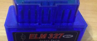
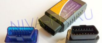
ELM327
Separately, we will introduce you to the ELM327 adapter, with the help of which many VAZ 2110 owners perform full diagnostics on their own.
ELM327 is one of the latest OBD developments. This scanner is used to check cars using a computer. The key advantage is that the device supports all known OBD protocols and interacts with many diagnostic programs. A USB cable is used to connect the device to a computer.
ELM327
The software for the ELM327 is mostly free, although some software is available only for a fee.
The adapter can work on computers with different OS. Namely:
- DOS;
- Windows;
- MacOS;
- Linux;
- PalmOS;
The full capabilities of the scanner can only be fully realized through properly selected software. For self-diagnosis, software for scanning the transmission and engine is available free of charge. Commercial versions of the programs allow you to additionally check other components of the car.
Key Features
Let's take a look at the capabilities that the ELM327 chip provides:
- Reads error codes and vehicle malfunctions;
- Displays codes and their descriptions;
- Exports data for printing, if necessary;
- Removes error codes;
- Displays data in metric and US measurement systems;
- Records, saves data, builds graphs;
- It has an acceleration counter from 0 to 100 km/h, which allows diagnostics on the go.
Many vehicle operating parameters must be checked while driving. Not all adapters are suitable for this, so it is important to choose equipment that suits your requirements.
Description of diagnostic connector OBD2 codes
OBD II
What is an OBD diagnostic connector?
It is very important that the presence of a similar connector does not mean 100 percent compatibility with OBD-II. Cars equipped with this system must have a mark on one of the plates in the engine compartment and/or in the accompanying documentation
The most commonly used protocol can be identified by the presence/absence of certain pins on the diagnostic connector. If all contacts are present on this connector, you should refer to the technical documentation for the specific car, which is available on the website.
OBD II diagnostic connector
Pin designation
- OEM
- J1850 Bus + Line, SAE
- OEM
- Body grounding
- Signal Ground
- Upper CAN Contact (J-2284)
- K Line ISO 9141-2
- OEM
- OEM
- Bus - Line, Sae J1850 Tire
- OEM
- OEM
- OEM
- Bottom CAN Contact (J-2284)
- L Line ISO 9141-2
- Battery voltage
Diagnostic connector pins for protocols used. Pins 4, 5, 7, 15, 16 - ISO 9141-2. Pins 2, 4, 5, 10, 16 - J1850 PWM. Pins 2, 4, 5, 16 (without 10) - J1850 VPW. ISO 9141-2 protocol is identified by the presence of pin 7 and the absence of pins 2 and/or 10 on the diagnostic connector. If pin 7 is missing, the system uses the SAE J1850 VPW (Variable Pulse Width Modulation) or SAE J1850 PWM (Pulse WidthModulation) protocol. All three data exchange protocols operate via a standard OBD-II J1962connector cable.
DTC Descriptions
The DTC consists of 5 digits. The figure below shows the structure of the DTC code. With this information, you can clear the DTC even if you do not have a description of the DTC.
List of the most common OBDII abbreviations
AFC – Air flow meter ALDL – Diagnostic connector. This is what the diagnostic connector for GM cars used to be called, as well as the connector for connecting a scanner; can also be used as the name of any OBD signal IICAN - ControllerCARB - California Atmospheric Resources BoardCFI - Central Fuel Injection (TBI)CFI - Continuous Fuel InjectionCO - Carbon MonoxideDLC - Diagnostic ConnectorDriving Cycle - The sequence of starting, warming up and driving the vehicle, during this cycle all tests are performed OBD Functions IIDTC – Malfunction CodeECM – Engine Control ModuleEEC – Electronic Engine ControlEEPROM or E2PROM – Programmable Read-Only MemoryEFI – Electronic Fuel InjectionEGR – Exhaust Gas RecirculationEMR – Electronic Ignition Reduction UnitEPA – Environmental Protection CouncilESC – Electronic Ignition ControlEST – Electronic ignition timing adjustmentFuel Trim - mixture composition balancingHC - hydrocarbonHEI - ignitionHO2S - oxygen sensor heatingISO 9141 - international standard for the OBDII connectorJ1850PWM - protocol for the OBD II connector, established according to the SAEJ1850VPW - protocol for the OBD II connector, established according to the SAEJ1962 standard - standard for the diagnostic connector OBD II installed to SAEJ1978 - SAE standard for OBD II scannersJ1979 - SAE standard for diagnostic modesJ2012 - SAE EPA approved standard for emissions test messages
MAF – air flow MAP – absolute pressure in the intake manifold MAT – air temperature in the intake manifold MIL – malfunction indicator lamp. "Check Engine Light" lamp on the instrument panel.NOx - nitrogen oxideO2 - oxygenOBD - diagnosticsOBDII or OBD II - an improved standard for vehicle diagnostics in the USA after 1-1-96Parameters - OBD diagnostic parameters IIPCM - Transmission control unitPCV - CarterProprietary Readings - Parameters on-board computer, which are not required for OBD II diagnostics, but can be used to diagnose malfunctions of various types of vehicles. PTC - Trouble Code RPM - rpm Scan Tool - scanner SES - engine service lamp on the instrument panel SFI - sequential fuel injection Stoichiometric ( Stoy'-kee-o -metric) Ratio – Fuel combustion ratioTPS – Throttle Position SensorVAC – VacuumVCM – Vehicle Central Control ModuleVIN – Vehicle Identification NumberVSS – Speed SensorWOT – Open Throttle
Protocol classification
It was not possible to bring everything to a single exchange protocol, since the system was developed and implemented by many manufacturers at once, and then continuously improved, which continues to this day.
It is also surprising that there are relatively few protocols. In aggregate, they can be counted about nine, although if you notice all the differences, then there are many more. But there are no special problems with compatibility; the scanners include all interfaces, from the first to the most advanced.
A
Class A protocols are the lowest speed, but at the same time simple, based on traditional computer serial interfaces, that is, they do not require significant power in the form of converting microcontrollers. Speed up to 10 kbps. This is what is called K-line.
B
Slightly faster and more complex interface serial protocols, better protected from interference, use various types of digital signal modulation. The speed is approximately 5-10 times higher.
C
So far the most modern protocols, these include the CAN bus, that is, the speed is about 500 kbit/s, the bit depth of code messages has been increased and other algorithms have become more complicated. Good noise immunity of a differential signal from a twisted pair.
ISO9141 protocol
It contains two wires K and L, although exchange is quite possible via a bidirectional K-line, without control via L. Previously, “laces” were widely used - universal K-line adapters. It works quite reliably, but very slowly.
J1850 VPW
Belongs to the group of protocols of the American J1850 standard. Used on GM vehicles. It works five times slower than the completely similar J1850 PWM used by Ford.
Interfaces differ in physical implementation, one- or two-wire lines, modulation in latitude or duty cycle. Described in one standard.
Where is OBD 2 located?
Where is the diagnostic connector on Renault Logan?
The location of the OBD 2 block is always indicated in the service manual, so it is better to clarify this point in the documentation.
The different positions of the diagnostic plug in a car are due to the fact that vehicle manufacturers do not use a single standard regarding the installation of pads. If the device is classified as J1962, it must be installed within a radius of 18 cm from the steering column. Manufacturers actually do not follow this rule.
The device location may be as follows:
- In a special slot in the lower casing of the instrument cluster. It can be seen in the center console in the driver's left knee area.
- Under the ashtray, which is usually located in the center of the console and instrument cluster. In this place, the connector is often installed by French car manufacturers - Peugeot, Citroen, Renault.
- Under the plastic plugs located on the bottom of the instrument cluster. In this place, the pads are usually installed by the VAG manufacturer - Audi, Volkswagen, etc. cars.
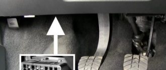
- On the rear of the center console, in the area where the glove compartment housing is installed. This location is typical for some VAZ cars.
- In the area of the handbrake handle, under the plastic of the center console. This situation is typical for Opel cars.
- At the bottom of the armrest niche.
- In the engine compartment, next to the engine shield. This is where the connector is installed by Korean and Japanese manufacturers.
If the car has a significant mileage, then the installation location may be different. Sometimes, due to electrical faults or damaged circuits, car owners move the connector.
User Ivan Matieshin, using the example of a Lada Granta car, showed where the OBD 2 diagnostic output is installed.
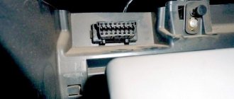
Connector location
So, we plan to check our car and we even have the necessary equipment. Now you need to find the connector - it is located at the bottom of the steering column, to the right of the driver. This connector is also called OBD. Knowing this name, it will be easier to find a suitable adapter.
If you believe the reviews, the K-Line connection device is considered the most successful adapter for VAZ cars. It has a lot of free space, so you can connect almost any testing equipment to it.
As for the main diagnostic device, it will be a computer. Of course, it is easiest to work with a laptop, since the process can be performed right behind the wheel of a car. But if there is only a stationary option, then you should take care of a long cord connecting the computer to the adapter.
Diagnostic connector type Priora
Where is the diagnostic connector located in a Lada Granta car?
During the development of “injection” cars, various options for interrogating the ECU (electronic control unit) were developed. At first it was a system for reading codes using a warning lamp. Under special conditions different for different injection systems, the warning lamp began to flash. The master could only write down the rhythm on paper and, checking the table, determine the error.
Subsequently, special diagnostic devices were developed:
- Diagnostic adapters for personal computers.
- Automotive diagnostic scanners.
There are separate articles describing the operation of these devices. But they undoubtedly have one thing in common: a special connector is needed to connect the equipment with the ECU. At first these plugs were made different for each brand of car. There were both round and square. And just paired holes for the dipstick, like on VAG systems. But gradually manufacturers began to think about unification. So, by the early 2000s, the OBD-2 diagnostic connector, now so widespread, appeared.
Attention! Some automakers, mainly producing expensive, exclusive brands of cars, continue to use “their” connectors. But Priora is equipped with OBD-2.
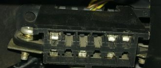
OBD-2 connector design and its contacts
This connecting plug is made of plastic. The connecting part looks like a trapezoid (see photo). In total, it has 16 female contacts. The countdown starts from the top row, from left to right. The top row is considered to be the wide side of the trapezoid. The following sockets are used for the Priora car:
- Ground (ground), slots 4 and 5.
- Constant “+” 12 Volts - 16.
- Diagnostic socket - 7.
Important! Sometimes other sockets are used in the Priora diagnostic connector. Typically these are communication lines with additional ECUs and an L-line for programming
You should not connect to them without special skills in working with software modules.
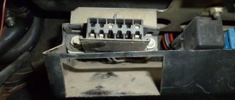
Typically, the equipment is connected to this connector through a special “plug”. The connector plug is of the same shape, but of the male type. Although those who work with various adapters can make connections directly. This is done on some types of adapters that have a separate probe for the K-line. You just need to remember that the “+” and “-” for the equipment must be taken from the battery of the vehicle being tested. Otherwise the communication signal will be incorrect.
Diagnostic connector location
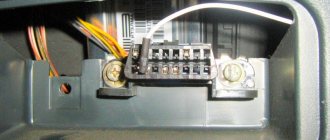
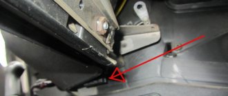
In addition to the fact that these connectors had different shapes, they were located in different places. On the Priora, it is hidden very cleverly. Without knowing where exactly it is located, finding it is very problematic.
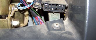
Don't let the fog in. The OBD-2 diagnostic connector on the Priora is located on the inner wall of the glove box on the passenger side. As they call it - the glove compartment. On the part that is adjacent to the “beard”. This is clearly visible in the photo. An experienced specialist, a master diagnostician, will connect with a standard connector by touch without any problems. Simply by opening the box and feeling for the nest behind its wall.
For novice diagnostic specialists, it is better to act according to the instructions. In order. That is, open the glove box completely. It will hang on the side plastic guides. Press these thrust plates a little, and the glove compartment will fold back further.
Carefully pull out the side tabs and release the glove box completely. Then access to the diagnostic input plug will be completely free.
Well, then proceed according to the instructions for connecting the available equipment.
Useful video about the location of the diagnostic connector on the Priora:
- Updating the Navitel application on Android
- Updating Navitel maps on Prestigio navigators
- Installing Navitel on Android
- Navitel maps update for Explay navigator
OBD 2 pinout
Connection diagram of contact elements to the diagnostic block:
- Backup contact. Depending on the manufacturer, any signal can be output to it. He is appointed by the car developer.
- Pin K. Used to send various parameters to the control unit. In many cars it is designated as the J1850 tire.
- A backup contact assigned by the vehicle manufacturer.
- "Ground" of the diagnostic block connected to the vehicle body.
- Ground of the diagnostic adapter signal.
- Contact element for direct connection of the J2284 digital CAN interface.
- Contact for connecting channel K in accordance with the international standard ISO 9141-2.
- Reserve contact element, assigned by the vehicle manufacturer.
- Spare contact.
- Pin required for connection to J1850 class bus.
- The purpose of this contact is determined by the machine manufacturer.
- Appointed by the car developer.
- Reserve pin assigned by the manufacturer.
- Additional contact element for connecting the digital CAN interface J2284.
- Pin for channel L, designed for connection in accordance with ISO 9141-2 standard.
- A positive contact for connecting the car's electrical system voltage, rated for 12 volts.
As an example of a factory pinout of a block, you can use the Hyundai Sonata. In these models, the first pin of the connector is designed to receive signals from the anti-lock braking system control module. Pin number 13 is used to read impulses from the ECU (electronic control unit), as well as airbag controllers.
Pinout types may vary depending on the protocol class:
- If the car uses the ISO9141-2 standard, then this protocol is activated by using pin 7. Pins numbered two and ten are not used and are inactive. To send information, contact elements 4, 5, 7 and 16 are used. Depending on the car, contact 15 can be used for this task.
- If the car implements the SAE J1850 type VPW protocol, then the second, fourth, fifth and sixteenth pins are used in the connector. General Motors vehicles of European and American production are usually equipped with such pads.
- It is possible to use the J1850 protocol in PWM mode. This application involves the additional use of the tenth pin. A similar type of connector is installed on Ford cars. Regardless of the type of output, the seventh pin is not used.
The MotorState channel spoke in detail about the pinout of OBD 2 diagnostic connectors for cars.
Connectivity and scanners
There are different ways to connect to OBD II inputs. The most modern ones include devices equipped with Bluetooth. In this case, gaining access to the on-board system requires a minimum of time and hassle. For Renault Megane there is a convenient OBD II scanner ELM 327 with a Bluetooth adapter. To gain access from a mobile device, use the OBD CHECK Torgue program, available in the official Android Market.
Please note that this scanner does not work with all Renault cars. Limited functionality is available for cars since 2006, but the device does not see all the sensors on earlier models, so to gain access we recommend a standard adapter and a desktop access program
In general, the adapter works with all cars that support the standard since 1996, both diesel and gasoline versions. Please note that diesel and gasoline engines of different modifications may differ greatly.
If you purchased an OBD II ELM 327 adapter, but it does not work, you can do a little restyling.
This can be done in some car services or yourself. Removing parameters from the lower tire was typical before 2004.
This scanner will especially appeal to diesel owners, as it helps monitor engine characteristics in real time. The program displays engine operating parameters and error codes. The device allows you to configure sensors, for example, engine speed, speed, coolant temperature. In general, the device is a serious help for maintenance.
Description of the Autocom program
List of supported ECUs:
Engine diagnostics using the OBD2 protocol - engine diagnostics using factory protocols - diagnostics of electronic ignition systems - diagnostics of climate control systems - diagnostics of immobilizers - diagnostics of transmission control systems - diagnostics of ABS systems - diagnostics of SRS Airbag systems - diagnostics of the dashboard and reset of service intervals - diagnostics of support systems comfort - diagnostics of body electronics systems
The GENERIC diagnostic program is a standards-based diagnostic program specifically designed to link and standardize fault codes. GENERIC is included for car and truck variants.
With the onboard recorder feature, you can record parameters in real time while the vehicle is moving. While recording, you can, with the press of a button, highlight and remember a specific error for the purpose of studying it later. TCS CDP+ is equipped with built-in memory, eliminating the need for a computer. Memory is not included.
With the Autocom multi-color indicator, you have complete control over the diagnostic process. Different colors and sound prompts will indicate to you which diagnostic stage is currently running. For example, if the indicator switches between blue and green, it communicates with the vehicle's control unit.
When Autocom is connected to a vehicle, the device will check the vehicle's onboard voltage and automatically adjust to the vehicle's 12 or 24 volt voltage level. If the voltage gets too high or too low, Autocom will alert you with both an audible prompt and an indicator light, as well as an alert via the battery icon in the software.
The software has a feature that allows you to read the chassis number from the vehicle you would like to diagnose. This ensures that the model and year are selected automatically. In addition, the engine code for vehicles that are usually available for reading is also automatically selected.
The Intelligent Scanning System (ISS) scans all the systems in the vehicle and displays the fault codes that are stored in each system. This saves time and gives you a quick overview of the current condition of the vehicle as a whole. Once the ISS is completed, you can select a dedicated management system to analyze the results further.
Intelligent System Identification (ISI) detects and automatically selects the type of controller that is installed in the vehicle. This ensures that the diagnostic session is completed correctly with the correct parameters as required.
According to this feature, you will be able to see the adaptations and adjustments that are possible for a particular vehicle without having the vehicle near you. Together, using the texts as a guide, you can plan and be effective in your work, even in difficult situations.
The Autocom car scanner is equipped with a unique multiplexer technology, which allows it to be used on all types of vehicles, regardless of voltage level and communication standards. For those vehicles that do not use a standard 16-pin connector, it is possible to connect special adapter cables.
Features of work
Features of using the imax b6 charger
After you turn the key to the “all inclusive” mode, the main electrical wiring components come into operation. However, the operation of electrical wiring begins when voltage is applied to the following electrical wiring elements:
- Interior lighting of the VAZ 2110.
- Parking lights.
- Rear brake lights.
- Electric fan from the cooling system.
- Sound alarm.
- Electrical wiring assembly for high beam headlights.
It is important to know: when the VAZ 2110 engine gets very hot, the electric fan continues to operate. And he does this even after stopping the engine.
The electric fan turns off when a warning signal is received from the thermostat.
All electrical equipment in the VAZ 2110 is protected from short circuits using electrical equipment fuses. But there are elements that do not have fuses:
- Electrical wiring elements for engine start and ignition circuit;
- Generator electrics;
- Injector wiring.
The main fuses can be found inside the mounting block. It is located at the bottom left of the steering wheel. All electrical components of the mounting block can be replaced. There is also a diagram of the mounting block, which shows the main fuses and relays.
What is OBD-II diagnostics Auto Other
OBD-II connector
Equipping a vehicle with an on-board diagnostic system of the OBD-II standard requires the presence of a special connector designed to connect diagnostic and control equipment to the vehicle. The OBD-II connector is located inside the cabin under the steering wheel and is a block with two rows of 8 contacts. The diagnostic connector is used to power the equipment from the vehicle battery, grounding and information transmission channels.
The presence of a standard connector saves time for car service center specialists, who thereby eliminate the need to have a large number of separate connectors and devices for processing signals coming from each connector.
Access to information and its processing
The OBD-II standard provides for the use of an error codification system. The error code consists of one letter followed by four numbers, indicating malfunctions of various systems and components of the vehicle. Access to information transmitted using the on-board diagnostic system allows you to obtain valuable data necessary for faster and better determination of the technical condition of the vehicle and troubleshooting existing problems.
In accordance with the ISO 15031 standard, the OBD-II data exchange system has various modes for reading, processing and transmitting information. Car manufacturers independently decide which modes to use for a particular car model. Manufacturers also independently determine which diagnostic protocol to use when using the OBD-II system.
There is special equipment for working with vehicle condition data according to the OBD-II standard. The devices differ in functionality and, in general, are an adapter that is connected to the car using the OBD-II connector and to the computer using a standard USB connector. The equipment comes with software that allows you to read and analyze information.
The diagnostic systems installed on modern vehicles include several devices that monitor parameters related to toxicity. The OBD diagnostic system also records failures in the on-board computer's memory, translating them into individual fault codes. The location of the diagnostic connector depends on the vehicle make and specific model.
You will need
Instructions
As an example, consider the location of the diagnostic connector on Opel vehicles. The OBD-II connector, by current standards, must be located within 16 inches of the steering column. The standards require eight locations for placing the diagnostic unit.
Inspect the area in the immediate vicinity of the steering wheel. If your Opel vehicle was manufactured before 1996, it uses a rectangular diagnostic connector with ten pins. The contacts are arranged in two rows in a vertical position and are marked A, B, C, D, E, going from bottom to top in the left row, and in the right - F, G, H, J, K (markings go from top to bottom).
On models manufactured after 1996, look for a diagnostic connector with sixteen pins arranged horizontally in two rows. The device has a trapezoid shape and supports the OBD-II standard.
If you have an Opel manufactured after 2000, look for the diagnostic connector under the front decorative panel (dashboard). In some cases, the device is closed with a separate cover.
On 1996-2000 vehicles, inspect the fuse box in the front panel, as well as the area under the plastic cover near the handbrake. This applies to Opel Corsa, Opel Omega, Opel Astra F.
To gain access to the diagnostic connector in Opel Omega B, Opel Astra cars produced between 1995 and 2000, disconnect the cover of the block where the fuses are located. This block is located in the passenger compartment, to the left of the steering wheel, in the dashboard.
To locate the corresponding diagnostic device in the Opel Zafira 2000-2004 model, first disconnect the cover located under the handbrake, and then remove the plug that protects the connector itself.
Open the ashtray cover located near the gearbox lever of the Opel Vectra C. Pull the ashtray body out. Now access to the desired device is open.
Video on the topic
Useful video
You can get more information about connecting to the diagnostic connector from the video below:
Any VAZ-2112 car is equipped with a system for self-diagnosis of faults, which can inform the owner about the presence of any fault without visiting a service station.
Such a system works by connecting special diagnostic equipment to it and further reading and decoding errors.
All about the international control system obd 2 pinout
Since 1996, there has been a need to check all manufactured vehicles for compliance with OBD standards. This was caused by the requirement to control the environmental situation. A brief description of the control device, location, functions is further in our article.
Brief description of the control device
The OBD-2 pinout designation is used to check compliance with the standard during diagnostics and monitoring of the operation of car engines and units installed on the chassis. The device is made in the form of a diagnostic connector for connecting devices that monitor exhaust gases and the operation of the entire car without interruption. The OBD-2 pinout is a set of requirements that all automakers must meet.
ATTENTION! Tired of paying fines from cameras? A simple and reliable, and most importantly 100% legal way has been found to stop receiving chain letters... Read more"
Location of contacts for obd 2 connectors
It is required that the connector be located in the passenger compartment at a distance of at least 18 cm from the steering column. The system is universal for all cars and has a standard digital CAN protocol, allowing data to be taken at any time. You can make detailed identification of various problems in the machine.
When diagnosing imported cars, additional lines K - Line and L - Line are used, as well as digital methods of transmitting indicators - CAN.
The monitoring function is supported by sixteen contacts:
- contact number one - it is installed at the manufacturer;
- the second refers to the J 1850 bus;
- number three is also put by the automaker;
- the fourth - for monitoring the grounding contacts of the car - chassis;
- number five controls the signal line ground network;
- contact number six is responsible for the CAN digital bus;
- number seven – ISO 9141 – 2, K – Line;
- eight and nine are installed by the automaker;
- the tenth controls the CANJ 1850 bus;
- numbers eleven, twelve and thirteen are also installed at the car plant;
- contact number fourteen controls the CANJ 2284 bus;
- fifteen – ISO 9141-2, L – Line;
- The sixteenth controls the battery voltage.
OBD adapters – 2 connectors for diagnostics
Cars of all brands must be equipped with an OBD-2 diagnostic adapter. It is used when diagnosing a car independently or in service centers. Are you looking for real homemade porn with juicy college girls? Yes, this is a cool genre, and thank heavens that we have plenty of such goodness. Follow the link and judge for yourself how cool the homework is, downloaded for free in our categories. For every taste, anal, incest, with mom or granny - all this will perfectly brighten up your evening. Especially with a beer it will go down with a bang, try it and don’t be shy about your wishes. The adapter is convenient for:
- diagnosing all car components;
- analysis of errors and mileage status;
- monitoring engine operation;
- for tension;
- temperature;
- speed;
- condition of panel instruments;
- you can track average and current fuel consumption;
- degree of engine warm-up;
- control the trips.
Connector functions provided by OBD-2 pinout
The main function of the OBD – 2 connector is to provide communication between the scanning device and control units. The pinout provides for connecting the vehicle power supply and grounding for successful operation of the vehicle scanner, without connecting a special power supply. When choosing a scanner, you should find out about its capabilities. The higher its price, the more accurate the verification will be. If it is not possible to purchase an expensive device, you need to choose a scanner made specifically for a given car brand.
The pinout allows the driver to combine his car with the OBD-2 diagnostic block.
If a non-compliance with certain exhaust gas composition requirements is detected, the CheckEngine signal appears, calling you to check the operation of the engine, and the light signal turns on. This is an indicator warning that the amount of harmful gases is exceeding the norm.
With the help of the obd 2 pinout system, vital parameters are monitored, the main one of which is clean air. The presence of the connector makes it possible to monitor the degree of serviceability of the vehicle without qualified, expensive assistance.
How to pay TWICE LESS for GASOLINE
- Gasoline prices are rising every day, and the car's appetite is only increasing.
- You would be happy to cut costs, but is it possible to live without a car these days!?
loading…
Let's sum it up
With the advent of computer diagnostics, car owners and repair specialists immediately appreciated the main advantages in the form of time savings, as well as the absence of the need to dismantle and test important components and parts of the car.
As a summary, we note that an adapter connected to the OBD-2 diagnostic connector of the VAZ 2110 and connected to the computer via a cable or wireless connection makes it possible to comprehensively test the car. If a particular malfunction is detected using the software, you can read the corresponding error codes to accurately decipher them.
Sources
- https://ladafakt.ru/gde-nahoditsya-razem-dlya-diagnostiki-vaz-2110.html
- https://remontvazov.com/samostoyatelnaya-diagnostika-vaz-2110
- https://vaz-2110.ru/elektrika-i-provodka/gde-nahoditsya-diagnosticheskij-razem-na-vaz-2110-raspinovka-soft-kak-ispolzovat.html
- https://vazweb.ru/desyatka/elektrooborudovanie/diagnosticheskij-razjom.html
- https://elm327.club/diagnostika-avto/raspinovka-razioma-dlea-diagnostiki.html
- https://cashbuzz.ru/hi-tech/1707-raspinovka-diagnosticheskogo-razema-vaz-2110-starogo-obrazca.html
- https://ladafakt.ru/raspinovka-diagnosticheskogo-razema-vaz-2110.html
- https://elm327-obd2.ru/diagnosticheskiy-razem/vaz-2114.html
- https://ladafakt.ru/raspinovka-diagnosticheskogo-razema-vaz-2114.html
- https://provaz07.ru/elektrooborudovanie/diagnosticheskij-razem-vaz-2107.html
- https://auto-self.ru/opredelenie-neispravnostey-vaz-2110-cherez-diagnostiku/
- https://avto-idea.ru/diagnostika/diagnostika-vaz-2110-svoimi-rukami-chto-dlya-eto-nuzhno/
- https://ladaautos.ru/vaz-2110/poshagovaya-instrukciya-po-provedeniyu-diagnostiki-vaz-2110-svoimi-rukami.html
- https://luxvaz.ru/vaz-2110/261-diagnostika.html
- https://KrutiMotor.ru/diagnosticheskij-razem-vaz-2110/
- https://elm327.club/diagnostika-avto/diagnosticheskij-razem-obd2.html
OBD adapters 2 connectors for diagnostics
Cars of all brands must be equipped with an OBD-2 diagnostic adapter. It is used when diagnosing a car independently or in service centers. The adapter is convenient for:
- diagnosing all car components;
- analysis of errors and mileage status;
- monitoring engine operation;
- for tension;
- temperature;
- speed;
- condition of panel instruments;
- you can track average and current fuel consumption;
- degree of engine warm-up;
- control the trips.
You can connect laptops, computers, and phones to the adapter. It is suitable for connecting to the OBD-2 system and all programs that are subject to their OBD 2 pinout requirements. The connection is made with a USB cable, Bluetooth or WI – FI. Using the adapter, you can test cars of all kinds of imported and domestic manufacturers.
Types of connectors
In modern vehicles, two types of diagnostic sockets can be used - classes A or B. Both connectors are equipped with 16-pin outputs, eight contacts in each row. The contact elements are numbered from left to right, respectively, components numbered 1–8 are located at the top, and 9–16 at the bottom. The outer part of the body of the diagnostic block is made in the form of a trapezoid and is characterized by rounded shapes, which makes it possible to connect an adapter.
The main difference between the different types of connectors is the guide grooves located in the center.
AutoEnginuity ScanTool
AutoEnginuity offers software products for BMW, Ford, GM, Chrysler, Nissan, Hyundai, Kia, Land Rover, Jaguar, Honda, Porsche and others. ScanTool is available for Windows and iOS operating systems.
The software allows users to quickly scan vehicle trouble codes and vehicle sensors to decide what vehicle intervention is needed. The main difference between ScanTool and others is its flexible scanning system.
The system can process data from ABS, airbags, gearboxes and many other regulators. Flexibility includes online data acquisition, bi-directional control, parameter reset, calibration and system test capabilities.
Autocom Cable Sets
There are universal kits on sale, for example, a set of Autocom CDP+ Trucks diagnostic cables - used to connect the Autocom CDP+ scanner to trucks with old-style diagnostic connectors.
List of cables included in the kit:
- Diagnostic cable Autocom - Knorr, Wabco Trailer 7 pin
- Diagnostic cable Autocom - MAN 12 pin
- Diagnostic cable Autocom - MAN 37 pin
- Diagnostic cable Autocom - IVECO 30 pin
- Diagnostic cable Autocom - SCANIA 16 pin
- Diagnostic cable Autocom - Mercedes-BENZ 14 pin
- Diagnostic cable Autocom - Renault 12 pin
- Diagnostic cable Autocom - VOLVO 8 pin
With the TRUCKS software package, you are able to perform brand-specific diagnostics for light and heavy commercial vehicles, buses and trailers since 1995. A total of 37 different brands.
Pinout assignment of OBD2 connector pins
| 1 | OEM (manufacturer's protocol). |
| 2 | Bus + (Bus positive Line). SAE-J1850 PWM, SAE-1850 VPW. |
| 3 | — |
| 4 | Chassis Ground. |
| 5 | Signal Ground. |
| 6 | CAN-High line of high-speed CAN bus (ISO 15765-4, SAE-J2284). |
| 7 | K-Line (ISO 9141-2 and ISO 14230). |
| 8 | — |
| 9 | Line CAN-Low, low-speed CAN Lowspeed bus. |
| 10 | Bus - (Bus negative Line). SAE-J1850 PWM, SAE-1850 VPW. |
| 11 | — |
| 12 | — |
| 13 | — |
| 14 | CAN-Low line of high-speed CAN Highspeed bus (ISO 15765-4, SAE-J2284). |
| 15 | L-Line (ISO 9141-2 and ISO 14230). |
| 16 | Power supply +12V from the battery (Battery Power). |
Pins 3, 8, 11, 12, 13 are not defined by the standard.
The first message on the screen of diagnostic equipment or a computer that causes panic among beginners is usually something like “No connection”, “No controller response” or something similar, but no less intriguing. The motor tester, for example, begins to offer options - from unconnected power to a hardware malfunction of the adapter. It’s good if the car with the immobilizer was the first to arrive for diagnostics and you are sure that everything is in order with the adapter. The reason for the lack of communication on cars without immo is trivial and is possible only in the domestic auto industry - a break in the diagnostic line running from the diagnostic connector to the ECU. The immobilizer uses K-Line to communicate with the ECU and is included in the diagnostic line break. If the immobilizer is not installed, then the diagnostic line hangs in the air and there is no connection with the computer. Apparently there was supposed to be a plug in this place, but... To restore communication, you simply need to install a jumper between pins 9-1 and 18 of the immobilizer connector (or install an immobilizer) as shown in the figure. In practice, to preserve the functions of smooth dimming of light, and simply to scare away pioneers, these two wires are cut and spliced, leaving the immo in the connector.
GAS diagnostic connector.
1 +12V 2 +12V from battery 10 L-Line 11 K-Line 12 Ground
Diagnostic connector VAZ
A - GND B - L-Line (may not be) M - K-Line G - Fuel pump control.
H - 12V. Constant from the battery through a fuse. /may not be.