What is it and features
The Lada Priora diagnostic connector makes a connection between the car’s control computer and a special diagnostic adapter or scanner. Manufacturers try to create their own connector in each car, but the functions remain unchanged:
- viewing and studying codes;
- determining the operating characteristics of the control system;
- cleaning diagnostic results;
- analysis of sensors with oxygen indicator;
- requests for diagnostic results while the vehicle is moving;
- control of actuators;
- View control indicators that were saved during fault codes.
Let us repeat, to perform the diagnostic procedure in a Lada Kalina car you will need a set of the following tools:
- laptop or other scanning device;
- adapter (as a fashionable alternative today, owners use a “Bluetooth” connection);
- diagnostic software product.
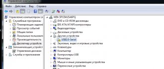
Now you can find the vehicle's diagnostic connector. In the Lada Kalina, its location is in a very suitable place, close to the transmission lever. The socket itself is covered with a plastic cover, which has latches. In the second generation, Kalina has a diagnostic connector, which is located with its own cover, that is, you immediately connect and scan.
Having found the diagnostic connector, we connect it to the adapter. We carry out this manipulation with the ignition off. When the owner of a Lada Kalina uses a wired adapter, then its second edge, equipped with a “USB” connector, is connected to the corresponding socket in the laptop.
When making self-diagnosis, the owner of a Lada Kalina should know that there are standard limits for parameters and indicators read from the car’s electronic systems. We recommend focusing on the regulatory values in order to gain an understanding of the correct functioning of the components subjected to the diagnostic process.
During the scanning procedure, the engine must be in idle mode. Now we compare each of the obtained parameters with the declared characteristics, which imply the normal functioning of the vehicle systems. If discrepancies with standard values are observed by more than 20%, then all units or components that indicate such failures are subject to repair, and if this is not possible, replacement.
When the control unit detects an error, the “check engine” symbol lights up on the dashboard. Such a phenomenon should force the owner to perform a diagnostic action. Each error has its own code, the decoding of which can be found on a specialized website on the Internet. The software itself has a corresponding section where these errors can be viewed.
Elm327 settings for Priora
Settings of the Torque Pro program for working with right-hand drive cars using the example of Toyota Mark II 2001 via ELM327
For right-hand drive Toyota Mark II (2001) Torque Pro, you need to write a command to programmatically reduce the speed of the ISO 14. and ISO 9. protocols (see the picture attached to the article)
For other models and brands of JDM (JDM-Japan Domestic MArket - Japanese domestic market), the following initialization lines should be entered to specify the protocol exchange rate:
Toyota Mark II 2001 y.o.: ATSP4n ATIB96n ATIIA13n ATSH82 13 F0n
Toyota Celica ZZT230: ATSH8213F1 n ATIB96 n ATIIA13
Toyota Vitz 01.2002: ATSH8213F1 n ATIB96 n ATIIA13, OBD2 protocol ISO 14230-4 (5b init, 10.4k baud)
Japan Domestic Market Nissan: ATSP5nATALnATIB10nATSH8110FCnATST32nATSW00
Japan Domestic Market Nadia/Harrier: ATIB96nATIIA13nATSH8213F1nATSPA5nATSW00
JDM Nadia/Harrier: ATIB96nATIIA13nATSH8213F1nATSPA5nATSW00
Toyota Common: baud rate - 10400 baud, ATIB10nATIIA13nATSH8013F1nATSPA4nATSW00
JDM Nissan(will test this with Xtrail): ATSP5nATALnATIB10nATSH8110FCnATST32nATSW00
Toyota Fielder: ATIB96nATIIA13nATSH8113F1nATAL
JDM Toyota Caldina Gt-Four( 2004 model) Protocol: ISO 14230-4(5b init, 10.4k baud), ATIB96nATIIA13nATSH8113F1nATSPA4nATSW00
For the rest of the majority of right-handed Toyotas, it is enough to write the initialization line: ATSH8213F1nATIB96nATIIA13
Source
Paper curtain
When supplying engine oil filters, manufacturers follow industry and government standards. Some characteristics, for example, the opening pressure of the bypass valve, are regulated by technical specifications.
Only companies whose products comply with international standards - ISO 4548 are suitable for the definition of leading brands. The human eye distinguishes hair with a thickness of 70 microns and 40 microns, but in the latter case it is already at the limit of visibility. Without a microscope, a person will not know what bacteria 2 microns in size and soot particles 0.6 microns in size look like.
Curtains of filter elements made of pleated and corrugated paper trap contaminants up to a maximum size of 40 microns. To increase filtration efficiency, synthetics are used.
With a two hundredfold magnification of the structure, you can compare the difference between paper and synthetics (left, right, respectively).
Structure of filter materials
The main differences between paper filters are:
- the presence inside a protective cage that retains pieces of paper when the cartridge is destroyed;
- Curtain ribs can be straight or zigzag, and can have different densities and quantities.
Cassette without protective clip
Zigzag filter fins
Unfortunately, it is almost impossible to see the density and number of curtain ribs through the threaded hole. But when compiling the next rating, experts cut non-separable cases and evaluate the specified parameters, making the information accessible to users.
Do-it-yourself diagnostics
Various breakdowns of sensors and other devices can cause increased gasoline consumption, incorrect engine operation, and increased wear of car system components. Despite the presence of errors, the VAZ Priora will drive until the driver has to make expensive repairs because of them.
VAZ Priora car
So that the motorist does not suddenly have to face the need for repairs, a special controller is installed on the VAZ Priora, with the help of which the driver can diagnose breakdowns. This can be done either using special additional equipment or an on-board computer installed in the car.
In fact, to carry out diagnostics, the car owner will only need to press a few buttons and count combinations of faults.
For example, you do not have a special tester, so we will look at diagnosing the vehicle for errors using the on-board computer. The BC is built into the dashboard and can be used to read combinations of faults. To do this, you need to activate the auto test mode.
The arrows on the dashboard move to maximum values when performing self-diagnosis of the vehicle
- First, turn off the ignition. After this, hold down the daily mileage reset button and turn on the ignition. Please note: the button must be held down.
- There is an LCD indicator on the vehicle's dashboard, keep an eye on it. When you turn on the ignition, all icons will begin to light up, and all arrows (speedometer, tachometer, antifreeze temperature sensor, gasoline level status) will begin to move to the maximum values and back. That is, if all the arrows behave as described here, this means that the sensors and indicators are functioning correctly.
- Now you need to find the button for switching BC functions - it is located on the right steering column switch. By clicking on it, the software version (1.0 and higher) will be displayed on the screen.
- Click on this button again. Combinations of faults will begin to appear on the screen. If necessary, you can reset error data here. To do this, press and hold the daily mileage reset button for about three seconds.
The appearance of a fault combination on the LCD screen during self-diagnosis
Video diagnostics with ELM scanner
There are two proven methods for finding problems on this modification of the car. Each has its own advantages and disadvantages.
Self-diagnosis using on-board computer
This method does not require the user to have additional equipment. All the necessary systems are already installed inside the machine. The processing sequence looks like this:
- Find the odometer reset key on the daily mileage;
- While holding the button, turn the ignition key.
If everything is done correctly, all the lamps on the dashboard will light up, the arrow indicators will make a full revolution and drop to the “0” position. In this way, the functionality of all vehicle systems is checked. If there is no response from any indicator, you need to check the circuit following the indicator. To more accurately determine the source of the problem, you can, in the same mode, press the mode scroll key to the “error codes” position, which in 90% of cases provokes the appearance of one of these indicators:
- 2 – short circuit or high voltage flow on the BS;
- 3 – the fuel level sensor in the gas tank is covered;
- 4 – antifreeze temperature sensor has burned out;
- 5 – error of the sea thermometer;
- 6 – severe overheating of the internal combustion engine;
- 7 – you need to check the oil level – the pressure has dropped;
- 8 – failure or jamming of the calipers, the pressure inside the line has dropped;
- 9 – battery “died”;
- E – failure or violation of the integrity of the EEPROM data packet.
To exit the menu, you must leave the on-board computer alone for 30 seconds. The main disadvantage of the method is its mediocre accuracy. The light only shows a broad problem in the design of the entrusted part of the machine. Thus, to more specifically identify the problem, you will need to resort to the following technology.
Checking via connected unit
Modern computers connect to the car's network via a diagnostic connector. The block is located inside the cabin, under the dashboard on the front passenger side. To work you will need a laptop or PC with the necessary software. After establishing a stable connection, an error code will appear on the unit’s display, explaining why the machine is acting up.
Standard codings were developed due to the sale of cars for export. It is inconvenient for the manufacturer to program each ECU for a different language. The standard cipher consists of 5 characters, each of which is responsible for a narrow range of information. One of these elements always comes first:
- P – malfunction of the power plant electronics;
- C – chassis electronics failure;
- B – problem inside the cabin;
- U – synchronization of two or more circuits is disrupted.
Next comes the first digit:
- 0 – OBD 2;
- 1/2 – enterprise code;
- 3- reserve
The data indicates a malfunction. The following indicates the serial number of the circuit containing the breakdown:
- 0 – exhaust gas system;
- 1/2 – fuel/air supply;
- 3 – ignition distribution system;
- 4 – additional control;
- 5 – violation of idle speed;
- 7/8 – gearboxes, differentials and drive axles.
The last two indices indicate the serial number of the breakdown.
Diagnostic connector for Lada Priora
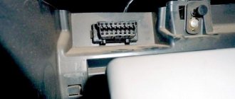
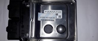
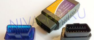
Modern cars, in the event of malfunctions in the operation of the engine or its systems, store errors in the memory of the electronic control unit (ECU). There is a special connector to connect it to diagnostic equipment in the car. The Lada Priora uses a standard European OBD-II connector.
Diagnostic connector Lada Priora OBD 2
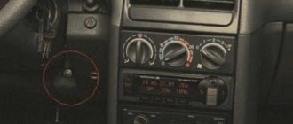
Diagnostic connector location
Diagnostic connector location
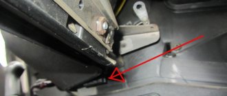
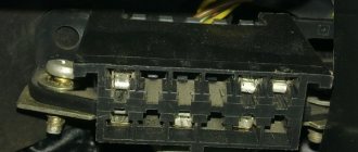
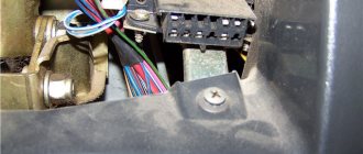
On Lada Priora cars, the diagnostic connector is located behind the glove compartment (glove box) on the rear wall on the left side. To gain access to the connector, open the glove compartment. Then disengage the glove box latches and lower it down.
Assignment of diagnostic block contacts
Assignment of diagnostic block contacts: 2 - J1850 Bus 4 - Chassis Ground 5 - Signal Ground 6 - CAN High (J-2284) 7 - ISO 9141-2 K Line 14 - CAN Low (J-2284) 15 - ISO 9141-2 L Line 16 - Battery Power
Error code: Renault Duster check engine light is on: causes and solutions
After reading the error codes, they are deciphered using the table:
Kalina/Priora on-board computer errors:
0102 Low level of mass air flow sensor signal 0103 High level of mass air flow sensor signal 0112 Low level of intake air temperature sensor 0113 High level of intake air temperature sensor 0115 Incorrect signal of coolant temperature sensor 0116 Incorrect signal of coolant temperature sensor 0117 Low level of temperature sensor coolant 0118 Coolant temperature sensor signal high 0122 Throttle position sensor signal low 0123 Throttle position sensor signal high 0130 Oxygen sensor signal 1 incorrect 0131 Oxygen sensor signal low 1 0132 Crankshaft sensor signal high 1 0133 Slow response oxygen sensor 1 0134 No signal from oxygen sensor 1 0135 Malfunction of oxygen sensor 1 heater 0136 Short circuit to ground of oxygen sensor 2 0137 Low level of oxygen sensor 2 0138 High level of high signal of oxygen sensor 2 0140 Open circuit of oxygen sensor 2 0141 Malfunction of oxygen sensor 2 heater 0171 Too lean mixture 0172 Mixture too rich 0201 Injector 1 control circuit open 0202 Injector 2 control circuit open 0203 Injector 3 control circuit open 0204 Injector 4 control circuit open 0261 Injector 1 circuit short to ground 0264 Injector 2 circuit short to ground 0267 Injector circuit short to ground sunki 3 0270 Short to ground in the injector 4 circuit 0262 Short to 12V in the injector 1 circuit 0265 Short to 12V in the injector 2 circuit 0268 Short to 12V in the injector 3 circuit 0271 Short to 12V in the injector 4 circuit 0300 Many misfires 0301 Misfires in cylinder 1 0302 Misfire in cylinder 2 cylinder 0303 Misfire in cylinder 3 0304 Misfire in cylinder 4 0325 Open circuit of knock sensor 0327 Low level of knock sensor signal 0328 High level of knock sensor signal 0335 Incorrect crankshaft position sensor signal 0336 Crankshaft position sensor signal error 0340 Phase sensor error 0342 Neither low signal level phase sensor 0343 High signal level of the phase sensor 0422 Low efficiency of the converter 0443 Malfunction of the canister purge valve circuit 0444 Short circuit or break in the canister purge valve 0445 Short to ground of the canister purge valve 0480 Malfunction of the cooling fan circuit 1 0500 Incorrect speed sensor signal 0501 Not correct speed sensor signal 0503 Interrupt speed sensor signal 0505 Idle speed control error 0506 Low idle speed 0507 High idle speed 0560 Incorrect on-board power supply voltage 0562 Low on-board power supply voltage 0563 High on-board power supply voltage 0601 ROM error 0603 External RAM error 0604 Internal RAM error 0607 Knock Channel Malfunction 1102 Low Oxygen Sensor Heater Resistance 1115 Faulty Oxygen Sensor Heater Circuit 1123 Rich Idle 1124 Lean Idle 1127 Rich Partial Load 1128 Lean Partial Load 1135 Oxygen Sensor Heater Circuit 1 open, short circuit 1136 Rich mixture in Light Load mode 1137 Lean mixture in Light Load mode 1140 Measured load differs from calculation 1171 CO potentiometer low level 1172 Potentiometer CO level high 1386 Knock channel test error 1410 Canister purge valve control circuit short circuit to 12V 1425 AD purge valve control circuit sorber short short to ground 1426 Control circuit of the canister purge valve open 1500 Open circuit of the control circuit of the fuel pump relay 1501 Short to ground of the control circuit of the fuel pump relay 1502 Short circuit to 12V of the control circuit of the fuel pump relay 1509 Overload of the control circuit of the idle speed regulator 1513 Circuit of the idle speed regulator short circuit to ground 1514 Idle air control circuit short circuit to 12V, open 1541 Fuel pump relay control circuit open 1570 Incorrect APS signal 1600 No communication with APS 1602 Loss of on-board voltage to the ECU 1603 EEPROM error 1606 Rough road sensor incorrect signal 1616 Rough road sensor low signal 1612 Reset error ECU 1617 Rough road sensor high signal 1620 EPROM error 1621 RAM error 1622 EPROM error 1640 EEPROM Test error 1689 Incorrect error codes 0337 Crankshaft position sensor, short to ground 0338 Crankshaft position sensor, open circuit 0441 Air flow through the valve is incorrect 0 481 Cooling fan circuit malfunction 2 0615 Starter relay circuit open 0616 Starter relay circuit short circuit to ground 0617 Starter relay circuit short circuit to 12V 1141 Malfunction of the oxygen sensor 1 heater after the converter 230 Malfunction of the fuel pump relay circuit 263 Malfunction of the injector driver 1 266 Malfunction of the force driver nki 2 269 Malfunction of injector driver 3 272 Injector driver fault 4 650 CheckEngine lamp circuit fault
Priors diagnostic connector: where is it located and why is it needed?
The operation of the car control system is checked using special devices. Therefore, to test the vehicle, you need to find the Priora diagnostic connector and connect the equipment. The work takes minimal time. You just need to know the rules for connecting and using the test device.
For Lada Priora, the diagnostic connector allows you to test the ECU. The connection is completed in a matter of minutes. The connector is located near the glove compartment. You can get to it by looking under the recess for storing various small items.
Many motorists want to know where the Priora diagnostic connector is located and how to get to it. This will allow you to independently check the car. It is executed after the testing program is launched. Troubleshooting will help solve the following problems:
1. Incorrect measurement of oxygen in exhaust gases.
2. Incorrect fuel distribution.
3. Irregularities in transmission control (automatic and robotic gearboxes).
4. In difficult cases of Lada Priora, the diagnostic connector will indicate problems in the firmware of the ECU itself.
It is important not only to know where the diagnostic connector is on the Priora, but also to be able to use it correctly. Therefore, before purchasing a testing device, you should study the testing features. The results obtained will indicate any problems in the operation of the ECU.
You just need to be able to understand these problems and learn how to correct them correctly
The results obtained will indicate any problems in the operation of the ECU. You just need to be able to understand these problems and learn how to correct them correctly.
But knowing in Lada Priora where the diagnostic connector is located, you can not only repair the car. In some situations, such knowledge can lead to vehicle theft. Burglars use the connector to disable the alarm. There are several measures to solve the problem.
It is better to move the Lada Priora diagnostic connector to a new location at a service station. Specialists will do the work quickly and accurately. The driver can also perform the move. However, to do this you need to disconnect the wires from the connector and connect them to a new connector. The old one can be dismantled or left.
For the Lada Priora, the diagnostic connector, correctly installed in another location, will work properly and without interruption. And only the driver will know about the true position of the connector. You can place it near the steering column. It is very convenient to place the new connector near the gear shift knob.
Having no idea where the diagnostic connector is located in the Priora, attackers will not be able to carry out theft. And the car will work reliably and efficiently. Therefore, the connection diagram must be strictly observed during transfer. This will guarantee the normal functioning of the installation and the ECU.
To understand where the diagnostic connector on the Priora can be located during conversion, you need to study other AvtoVAZ models. Predecessors have a different connector location. Only design differences should be taken into account. The supply wires should not interfere with other car systems.
Anti-theft protection for connector
The connector also helps thieves. By connecting to it, the attacker can easily turn off the car alarm, and his further actions will be predictable. The whole problem is that the thief knows in advance the location of the plug, which simplifies his life, and connects to it immediately after opening the car door.
The plans of attackers can be ruined if the diagnostic plug is moved to another place in the car. This is most often done at service stations, so it is recommended to entrust this operation to specialists. If you do this yourself, you should first think about where to put the plug so that it “does not catch your eye.”
In words, everything is quite simple: remove the plug, disconnect it, put it in a new place and reconnect the wire block. In fact, you will have to dig a fair amount into the inside of your Priora, but it’s worth it if you want to take care of protection against theft.
The diagnostic plug will make life easier for the owner of a Lada Priora - instead of torturing yourself with a tool in your hand, digging in the engine compartment, you just need to get this “adapter”, find out the reason and only then start repairing.
Additional signals about the causes of the malfunction (1000)
- 102 – the DC heating resistance has disappeared;
- 115 – circuit failure of the same sensor;
- 123/124 - violation of mixture formation in the absence of load - idle is acting up;
- 127/128 – duplicates the previous signal in partial load mode – jerks, dips or jerks when pressing the gas pedal lightly;
- 135 – open circuit or short circuit of circuit DK1;
- 136/137 – violation of the formation of a combustible mixture at minimum load;
- 140 – potential difference between measured and actual load;
- 171/172 – incorrect operation of the potentiometer;
- 386 – incorrect detonation channel test result;
- 410/425/426 – short circuit to the sides or ground/break in the lines of the canister purge valve;
- 500/501/502 – open circuit with short circuit of the fuel pump for ground and 12V, respectively;
- 509 – overload of the XX regulator;
- 513/514 – short circuit of the throttle position in position XX;
- 541 – there is no power to the fuel pump or the integrity of the housing may be damaged with fuel getting inside;
- 570 – an incorrect signal from the APS design is received;
- 600 – no impulse is received from the APS; there may be a breakdown or the unit is coming off;
- 602 – 12V short circuit to the electronic engine control unit;
- 603 – problems with the firmware, can be resolved by rebooting;
- 606/616 – interruptions in the operation of the rough road sensor;
- 612 – incorrect ECU reset code – the system did not reboot;
- 617 – the rough road sensor has died or a short circuit has formed;
- 620 – critical fault in the EEPROM;
- 621 – critical RAM fault;
- 622 – failure or breakdown of the EEPROM;
- 640 – conflict in checking firmware status;
- 689 - diagnostics showed that all vehicle systems are in order - erroneous codes were displayed.
Error code: Volga diagnostic connector pinout
Refinement of the VAZ 2110 OBD connector: independent connection of the elm 327 adapter
There is a special “CheckEngine” light on the dashboard of the VAZ 21110 car. When the ignition is turned on, the light comes on and while the vehicle’s internal combustion engine is not running, a special program reads data from all units and systems of the vehicle, transmitting data on fault detection to the on-board computer.
If, after starting the vehicle’s internal combustion engine, the “check” does not go out for another 10 seconds, it means that faults in the system have already been identified and the corresponding error codes have been entered into the memory of the on-board computer.
VAZ 2110 cars are equipped with a “January-4” controller, which does not provide feedback and the “check” lights up and there is a fault detection signal. Error codes in such a controller are calculated starting from “12” and ending with “61”.
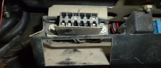
The codes are deciphered either with a special diagnostic device or independently. Using the example of the VAZ 2110 “January-4” ECU, we will consider the algorithm for performing diagnostics independently:
- connect contact “B” of the diagnostic block and “ground”;
- turn the ignition key to the third position without starting the car;
- the “CheckEngine” light illuminates the code “12” (the light flashes once -1, after a pause of two seconds it flashes twice in a row -2 flashes three times in a row (the program has started diagnostics);
- the program will detect the malfunction by displaying the corresponding error codes (flash, pause).
Some tips for installing a modern ELM 327 adapter with the OBD-II program (protocol) for the VAZ 2110:
- purchase an adapter along with a cable;
- study the installation instructions (pinout of the block and location of each connector);
- You must insert your own cable into each connector of the block, checking the pinout; it must comply with the manufacturer’s instructions.
Let us also add that programs for determining faults of the ELM 327 adapter are downloaded from various sources on the Internet.
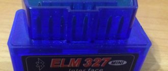
Diagnostics of VAZ PRIORA using a smartphone and OBD 2 Bluetooth Car ELM 327 Reader Diagnostic Scanner
Often those who purchase OBD scanners for self-diagnosis of their car have questions about how to diagnose a car with only a smartphone with an Android system and Bluetooth ELM 327 OBD 2 scanner.
In this article we will try to describe the diagnostics step by step using the example of the VAZ PRIORA diagnostics.
For other brands of cars that support OBD 2 , everything is the same, the only difference is in the location of the diagnostic connector and in the number of sensors available for diagnostics; if your car model does not have any control sensor, then it is simply not in the list of available for diagnostics.
So we have an OBD 2 Bluetooth Car ELM 327 Reader Diagnostic Scanner and a smartphone without any identifying markings. Having rummaged through the menu, we find the item ABOUT THE PHONE and read: ANDROID 4.1.2; Model GT-I9500 i.e. a Chinese analogue of the Samsung GALAXAY S4, for our purposes any Android smartphone will be suitable and you will need to install the TORQUE - diagnostics and engine control - the most convenient in my opinion and you can easily download the Russified version from the Internet.
1. Find where in the car the OBD 2 diagnostic connector is located in the VAZ PRIORA (station wagon), it was found when opening the glove box (glove compartment) behind it on the left side, on the website shop.avtoc.com in the article about the diagnostic scanner for PRIORA this is the location It has already been suggested that there is no need to disassemble and remove the glove box because the scanner is small-sized and fits perfectly into this connector when the glove compartment lid is open, although it is poorly visible and probably the designer could have chosen a more convenient place.
2. We insert the scanner into the connector without distortion; you can illuminate it with a flashlight if it’s a little dark in the garage and you can’t immediately touch it
3. You don’t need to start the engine right away; first you need to pair the scanner with your smartphone
SYSTEM SETTINGS menu item, find the Wi-Fi SETTINGS item and the Blueto SETTINGS item. Wi-Fi SETTINGS can be switched to OFF mode, but Blueto SETTINGS.., be sure to switch to ON mode and then hold your finger on the inscription of this setting, enter the submenu where there will be an inscription about searching for devices and a list of available devices - in addition to OBD II, there may be, for example, BT-300 (wireless earphone) if you have connected such a device previously. If the scanner is connected for the first time, a window will pop up prompting you to enter a code of four zeros or a sequence of numbers 1234,
we point our finger at this empty line and a very inconvenient keyboard appears on the screen, but after several attempts we manage to dial 1234 and press ok ,
we see the message OBD II paired but not connected
That's how it should be!
4. Start the car engine,
We pick up the smartphone again and run the pre-installed TORQUE
If, when starting the program, a message pops up to CALIBRATE, answer NO,
This can be done as needed later.
Place your finger on the screen just below the inscription GRAPHICS and moving your finger in a semicircle will display several more menu items - we are interested in the inscription ADAPTER STATUS, press your finger and view information about the scanner we have connected to the car
Having thus verified the functionality and normal wireless data exchange, you can also interrogate the scanner about its software version, etc., see which vehicle sensors are available for diagnostics
Yes, Priora doesn’t have that many sensors available for diagnostics - I counted seven) and plus duplication of all dashboard readings
5. Let's return to the main TORQUE and start diagnostics by clicking on ERROR CODES
Further actions do not require comments, you need to wait a couple of minutes and if everything is fine, you will receive green inscriptions on the smartphone screen next to the names of the sensors
if an error pops up along with the decoding, for example 304 - ignition system error, then this indicates the need to take the spark plug wrench and replace the 4th spark plug
TORQUE has many fine settings, but the initial diagnosis of the car can be done right away without worrying about the engine size, etc.
In conclusion, about one noticed subtlety - if in point four, when you launch the diagnostic program, you do not see all the green checkmarks in the ADAPTER STATUS, then with the car engine running, on the smartphone we again go to SYSTEM SETTINGS in Blueto SETTINGS.., and if the OBD II inscription is paired with not connected remains unchanged, then we point our finger at this inscription, and when prompted to disconnect the device, we confirm the disconnection, then we search for devices again, enter the 1234 , and as a result, after re-entering we should get OBD II paired and connected
and you can return to the running diagnostic program.
Why is diagnostics needed?
The purpose of diagnostics, as stated above, is to accurately determine possible malfunctions that may occur during vehicle operation. If any symptoms of breakdowns appear in the operation of the car, but you cannot accurately determine the fault yourself, then you can try to diagnose the car.
But this is only a general purpose; more specific reasons for the check are listed below:
- The need to perform this process usually appears when indicators appear on the control panel that warn the car owner about a breakdown.
- In practice, this procedure is often carried out in the event of malfunction of one or more units and components of the car. The completed check will allow the car owner to give an accurate answer as to whether these mechanisms have really failed or not.
- When purchasing a vehicle. Thanks to computer error recognition, a potential buyer can determine without the help of specialists how correctly the power unit, gearbox and suspension are working.
- In addition, the need for this process may be due to a reduction in the possible costs of repairing the machine in the future. In other words, we are talking about preventive diagnostics; according to many experts, it is better to perform such a task at least once a year. If the car owner learns about possible malfunctions in advance, before the car becomes impossible to operate, then he will be able to reduce the financial costs of repairing it (the author of the video is the CompsMaster channel).
VAZ auto electrician on-site
The computer diagnostic service with on-site VAZ (LADA) cars in Moscow is in a hurry to provide immediate technical assistance in any difficult situation on the road. You don't have to waste valuable time moving your car to a car service center. A knowledgeable auto electrician and VAZ (LADA) diagnostician will come to your call point.
We provide roadside assistance and will be useful in:
- auto electrician visit
- repair of immobilizer of any manufacturers
- emergency car opening
- emergency door opening
- opening locks
- light the car
- charge the battery
- computer diagnostics
- troubleshooting
- delivery of gasoline to the site
- electrical repair
- eliminating found problems
- diagnostics of electrical equipment for heated windows
- checking the condition of the electrical wiring
- programming of car control and car alarm units (if necessary)
- replacing broken auto parts
- installation of additional electrical equipment
- It’s not clear, but something is wrong with the car
- other failure variations
How to remove and check the sensor
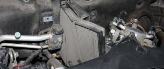
Access from above to the Priora DD is difficult due to the intake module located above it. The easiest way to get to the sensor is from below, first removing the engine protection or at least unscrewing and folding its front part. When working from above, you will have to do everything by touch. In any case, before starting work, it is necessary to disconnect the ground wire attached to the “negative” terminal from the battery.
To remove the crankcase protection, you need to:
- unscrew 5 nuts with a 10mm head;
- unscrew the 2 19 nuts installed on the back of the shield;
- remove protection.
- by pressing the metal latch of the DD connector, disconnect the block of wires going to the controller;
- using a 13mm wrench, loosen the bolt securing the sensor;
- Unscrew the bolt and remove it from the threaded hole, removing the sensor.
- We connect a multimeter to the DD terminals. We set the device to voltmeter mode, choosing a measurement limit of up to 200 mV.
- We take a metal object - pliers or a bolt - and lightly tap it on the DD.
When you tap on a working sensor, the voltmeter will show voltage surges. A faulty DD will not react in any way. A more accurate diagnosis of a removed sensor can only be done using a special stand.
Installation of a new DD is carried out in the reverse order of dismantling. Experts recommend installing a similar Bosch instead of the “native” one. Before going to the store for a new sensor, you should write down the markings of the removed sensor. Tightening the bolt securing it to 13 should be done with a slight force - 10.4–24.2 N m (1.1–2.5 kgf). Tightening too tightly will affect the operation of the sensor.
Problems with engine detonation can occur due to various faults. They are often associated with the operation of the electrical circuit from the knock sensor to the electronic control unit, or with the knock sensor itself. The diagnostic scanner can detect 4 common knock errors - P0325, P0326, P0327 and P0328.
Types of equipment used to check LADA
A list of diagnostic devices used not only in specialized car services, but independently, for example, in a garage. • Odometer correctors, with setting mileage values; • Models that support protocols, by reading information, erasing errors, codes are deciphered: ELM327 USB / Bluetooth / Wi-Fi running on the elm327 chip; • Vag adapter (cable) for later versions of the ECU and 12 pin pads; • Testers whose work is organized on the basis of oscilloscopes.
Diagnostic devices that support combination with ABS and SRS units, as well as using a CAN bus, are in demand.
Modern popular models
The best diagnostic scanners compatible with the VAZ have been selected for review. We pay attention to the following samples:
Scan Tool Pro
Scan Tool Pro is a compact adapter without an external environment, built on a universal microprocessor elm327 (basic) Chip version v.1.5 (PIC18F25k80). This diagnostic OBD2 scanner is used in conjunction with a laptop or smartphone; it has Wi-Fi and Bluetooth versions.
The device is practical and reliable, so it is sold out from official dealers very quickly. Reviews for this adapter are mostly positive, but it is difficult to purchase due to the shortage of original versions. Supports all common protocols and car brands.
Scan Tool Pro Black Edition - budget multiscanner
A good choice for a novice diagnostician. New 2021
Nowadays there are scanner models with different versions of firmware and chips on sale. Scan Tool Pro with firmware 2022 is the most stable version so far, and also has maximum compatibility with cars manufactured since 2001 (Russia, Asia, Europe, States). You can buy Bluetooth scanners for car diagnostics of the Scan Tool Pro brand from an official dealer who provides a 12-month warranty using the link on the right. Happy diagnostics!
Launch Creeder VII
Launch Creeder VII. A semi-professional tool for self-diagnosis of modern engine control systems and ECUs. Suitable for domestic cars equipped with an electronic control unit. There is an external display and built-in software.
This version has a complete base for Russian cars, the adapter is even suitable for VAZ 21124. Optionally, the kit includes adapters for various brands of cars.
Bosch KTS 590
Bosch KTS 590. Refers to professional diagnostic equipment and is more expensive than the previous car scanner. The device is connected to a laptop or desktop PC, and there is also an external display.
The kit includes an oscilloscope and a digital multimeter. It is possible to carry out not only computer, but also instrumental diagnostics of electrical circuits and connections. Well suited for car repair shops
Scanmatic 2
Scanmatik 2. The device has shown itself very well with Russian cars. Scanmatic 2 is characterized by fairly high operating efficiency; it reads information using a tablet or smartphone.
Supported protocols: OBDII/EOBD (13 x ISO-9141/ISO-14230 (KLINE); 1x High Speed CAN (ISO-15765); 1x Single Wire CAN (GM-LAN). 1 x J1850 VPW; 1 x J1850 PWM; 1 x Medium Speed CAN (GM-LAN).The kit includes adapters for various brands of cars, additional adapters can be purchased from an official dealer.
Launch X431 Pro
Launch X431 Pro. Leader of the Russian market of equipment for auto diagnostics. Since 2016, it has been supplied with a DBS Car II adapter, as well as a tablet with large memory for programs and high-capacity batteries.
More than 100 supported car brands and maximum access to car electronics. The most expensive and presented options.
VAG adapter (VAG-COM 409.1)
VAG diagnostic cable K-line (VAG-COM 409.1). The adapter is made on an FTDI chip and is well compatible with the January, MIKAS and other ECUs installed on domestic cars, including GAZ. It is not so convenient to connect wiring to it (there are no clamps). It is more often used for diagnosing cars produced before 2006.
Connector design
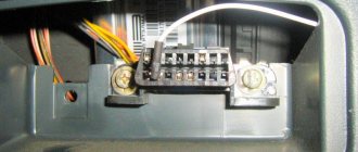
The functionality and pinout of the obd2 connector is made according to a two-component circuit without symmetry and includes sixteen knife-shaped contacts. These contacts are located in the block parallel to each other with a guide key. Their numbering in the block is done from left to right, with the top line of contacts indicated by numbers 1-8, and the other row with 9-16. The connector design is made of durable plastic, and the contacts themselves are separated by a special longitudinal plate.
To ensure correct polarity when connecting the male connector to the female socket, a trapezoidal design with slightly rounded corners is provided. The functions of the contacts in the connector have two groups of assignments. One of which is made according to a standard design, and the manufacturer has the right to use the other group at his discretion to perform certain tasks.
The wiring of the obd2 connector with the definition of the function of each contact is shown in the table below:
| 1 | Branded |
| 2 | J1850 bus |
| 3 | Branded |
| 4 | General grounding |
| 5 | Signal ground |
| 6 | CAN bus |
| 7 | Line K according to ISO 9141-2 |
| 8 | Branded |
| 9 | Branded |
| 10 | J1850 bus |
| 11 | Branded |
| 12 | Branded |
| 13 | Branded |
| 14 | CAN bus |
| 15 | Line L according to ISO 9141-2 |
| 16 | 12 V |
A distinctive feature in the design of the obd2 connector is that it has a socket for connecting the on-board network. And this makes it possible to use scanners without resorting to the use of an additional power supply circuit. Since the advent of the first obd2 connectors, which were only capable of displaying information about an existing problem, a lot has changed.
How to use
Before purchasing an adapter, make sure it is compatible with your car. After purchasing the adapter, it is important to correctly connect the scanner to the connector. As a rule, the OBD 2 connector is located in the passenger compartment under the dashboard. Models before 2006 usually have a 12 pin connector (GM), and to connect the scanner you will need a 16 pin adapter.
Information on the location of the connectors is presented in the table and photo below.
| No. | Brand VAZ | Connector location | Suitable and recommended scanners + program |
| 1 | 2105, 2107 (with injector) | On the left side of the steering column | VAG-Adapter + Adapter 12 pin + OpenDiag Mobile |
| 2 | 2108, 2109 | Below the storage shelf, in the center. | |
| 3 | VAZ 2113, 2114, 2115 | In the cigarette lighter area, approximately 10-12 cm lower. | Scan Tool Pro + 12 pin adapter + OpenDiag Mobile |
| 4 | VAZ 2110, 2111, VAZ 2112 | On the right side in relation to the steering column, under the dashboard. | |
| 5 | Lada Priora, Kalina, | In the opening located behind the glove compartment. | Scan Tool Pro 2022 + OpenDiag Mobile |
| 6 | Lada Vesta | Located under the steering column on the left, on the left near the handle for opening the hood, under the mounting block | |
| 7 | Lada Largus | Inside the glove compartment on the back wall and closed with a protective cap | |
| 8 | Lada Granta | Right above the cigarette lighter. |
Location
Often faced with a problem where the diagnostic connector is located. In each car they are installed differently, taking into account the specifics of the entire structure. As for Prior, everything here is done quite cleverly. If you don't know the exact location, it will be difficult to find.
Error code: Where is the diagnostic connector on Renault Logan, Megane and Duster, and how to diagnose it yourself?
Car manufacturers have placed a diagnostic connector in the glove box. You can find it on the passenger side in the interior. Simply put, look in the glove compartment. If you contact service centers, specialists will immediately find the required design. Beginners need to be more vigilant in this matter.
It is best to work according to already compiled instructions. Let's take a closer look at the process:
- We completely open the glove box and clear it of foreign objects to make it easier to work.
- The glove compartment should hang on plastic guides on each side.
- We press on the side plates so that the small door opens further. This will make it easier to work and find the Priora diagnostic connector.
- We pull out the tabs on the side and completely remove the glove box from the latches.
- Provides access to the input plug for diagnostics. Now he is free and ready to go.
Access to the device is open. The following operations directly depend on the purpose of “opening” your car. More often they get to the connector to reconnect it or check the correct signals from the ECU. This way his work will be adjusted and will not create problems or unforeseen situations.
Glove compartment in a Lada Priora car
OBD connector location
Lada Granta obd connector
If you have purchased a diagnostic adapter and do not know where the OBD 2 diagnostic connector is located in your car, then this article will come in handy. The article will tell you where the diagnostic connector is located on cars of various brands: VAZ, GAZ UAZ, Chevrolet, Reno and others.
The diagnostic 14-pin connector on a VOLGA car is located under the hood, on the wall of the engine compartment, on the passenger side
On newer models, this connector is already standard OBD 2 located under the steering wheel (a similar location in Gazelle cars of recent years)
On a VAZ 2110 - 2112 car, the diagnostic connector is located to the right of the driver, next to the steering column at the bottom.
On a VAZ 2109 with a high instrument panel, the diagnostic connector should be found on the shelf under the glove compartment, next to the car's ECU.
On cars of the VAZ 2108-2115 model range with a “European panel”, the diagnostic connector is located in front of the gearbox, directly under the cigarette lighter. The diagnostic connector is covered with a decorative cover.
On the Kalina car, the diagnostic connector is also located behind the decorative cover near the gearshift knob
On VAZ Priora cars, the OBD diagnostic connector is located on the rear wall, behind the glove compartment.
On UAZ cars, the diagnostic connector is located either under the hood near the wall on the left of the driver (goat), behind the driver's seat (loaf), under the steering column on new cars like UAZ Patriot.
On Reno cars, the diagnostic connectors are located either behind the glove compartment; if you open it, you will see a diagnostic connector at the very end of the far wall behind the decorative cover, or under the steering column from below.
On Chevrolet cars, the diagnostic connector is also usually located under the steering column at the bottom, or to the right of the driver on the side of the center console, near the driver’s right foot (Chevrolet Lanos).
The process of diagnosing a Lada Priora car using an on-board computer
First of all, you need to know how to reset the parameters using the button to reset all daily mileage indicators. It is located on the instrument panel. You must press this button and, while continuing to hold it, you must simultaneously turn on the ignition using the key.
At this time, at the beginning of the diagnostic process, all arrows on sensors and instruments should show a jump from the minimum to the maximum indicator, at the same time at this moment all the necessary indicators and errors for checking the car should be shown on the liquid crystal display.
If at this moment any arrow does not show the correct movement or any position on the display does not appear, then you need to check the sensors and systems of the car for errors. Also, do not forget to check the display itself for faults, because A situation is possible when the car is working correctly, but errors are shown on the display solely due to the separation of any contacts.
Now, in the same mode of self-checking the car, you need to double-click any button that is responsible for switching the operating mode of the on-board computer. After these steps, certain numbers should appear on the on-board computer’s LCD screen. These are the Lada Priora error codes.
| Error code | Decoding |
| 2 | There is quite a strong voltage in the on-board control system. |
| 3 | Malfunction of the sensor, which is responsible for indicating the presence of fuel in the fuel tank. |
| 4 | Problems with the liquid that is responsible for cooling (its temperature readings may be inaccurate). |
| 5 | Failure in the system of sensors responsible for reading the air temperature outside the car |
| 6 | Engine overheating. |
| 7 | The oil pressure level will drop critically. |
| 8 | Problems in the braking system |
| 9 | The battery is dead. |
| E | There were malfunctions in the information package that was stored in the EEPROM |
Test program activation
On Priora you can easily activate testing. This will help you recognize problems yourself and begin to solve them instantly. The test program allows you to solve common car problems, namely:
- fuel supply adjustment;
- searching for breakdowns in the transmission and neighboring structures;
- identify breakdowns and flaws in the firmware of the electronic control unit.
Brief conclusions
Owners of this brand should be aware of the location of the connector. This way you can be sure that you will always be able to identify problems in a timely manner. The main thing is to understand where this system is located and how to work with it.
The diagnostic connector of a Priora car is a plug, by connecting to which you can identify 80% of breakdowns related to electronics. Of course, the diagnostic plug will not show whether the valve is bent or whether the pump is worn out, but believe me, it knows and can do a lot. Knowing this, car thieves take advantage of this. It’s very easy to steal any modern car, be it a Priora or an Infiniti, if you know where this connector is located.
The presence of a diagnostic connector on the Priora OBD is a vital necessity. In a modern car, it is often impossible to just look under the hood and immediately determine the problem. This is explained by the fact that the operation of all components of the car is coordinated by an electronic control unit - a small computer with which you need to find a common language.
You will have to use the diagnostic connector of a Lada Priora car at least once during its operation. Before buying a connector, you need to find out more about where the connector is located, how it is designed, what it is needed for, and what operation can be used to secure the Priora from theft. Read the article to the end and we will talk about the topics: diagnostic plug pinout, anti-theft protection, where to find it!
Pinout
Where is the diagnostic connector on the Granta fret? Knowledge of the pinout may be required if a car enthusiast wants to make an adapter for computer diagnostics with his own hands, or if you need to connect without it. Experts recommend buying ready-made devices without the need to make a plug yourself.
However, if you do not have such an opportunity, and diagnostics need to be carried out urgently, we will consider two main pinout options used on VAZ cars of various years of manufacture. Until 2002, AvtoVAZ products used the following pinout option:
- The 4th and 5th pins are GND outputs.
- 16th pin – 12 V (power line).
- The 7th contact is the diagnostic line itself.
Since 2002, the pinout scheme has changed significantly. Now it looks like this:
- Pin H – 12 V (power line).
- Contact G – 12 V for the fuel pump.
- Pin A – GND output.
- Contact M – diagnostic line.
There is one important note to note regarding this diagram. If you connect the connector without a block, but directly, it is recommended to use the charge from the cigarette lighter as a source of electricity
The peculiarity of this pinout is that contact H is not always routed in the car. The use of G is also not recommended because high frequency current is supplied. This can have a negative impact on the adapter, even to the point of burning it out.
As you can see, the pinout on VAZ cars of different ages is sometimes very different. Therefore, we advise you to look at the registration certificate of your car and find out what year it is made. On older vehicles you will not find the new pinout design as it did not exist yet and on newer vehicles the old design was no longer used.
Test program activation
On Priora you can easily activate testing. This will help you recognize problems yourself and begin to solve them instantly. The test program allows you to solve common car problems, namely:
- fuel supply adjustment;
- searching for breakdowns in the transmission and neighboring structures;
- identify breakdowns and flaws in the firmware of the electronic control unit.
Brief conclusions
Owners of this brand should be aware of the location of the connector. This way you can be sure that you will always be able to identify problems in a timely manner. The main thing is to understand where this system is located and how to work with it.
Location of the diagnostic connector on the Prior
The diagnostic connector in the Priora was shoved into a very inconvenient place. Inside the glove compartment. I would tear off the hands of whoever came up with the idea to do this.
This is very inconvenient if you are taking measurements on the go; you cannot close the glove compartment. You also cannot leave the adapter there and close the glove compartment. If you are looking for a malfunction and need to look at the diagnostic data on your next trip, you will have to open the glove compartment again and install the connector. Well, change the front passenger.
This is very inconvenient if you are taking measurements on the go; you cannot close the glove compartment. You also cannot leave the adapter there and close the glove compartment. If you are looking for a malfunction and need to look at the diagnostic data on your next trip, you will have to open the glove compartment again and install the connector. Well, change the front passenger. The easiest way is to use a “short” adapter, like the one in our photo.
If you need to constantly read data, the connector can be moved to a more convenient location.