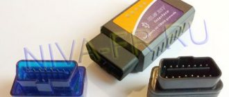
Lada Vesta, like any other modern car, is “stuffed” with electronics. The OBD diagnostic connector is needed to check all these systems. Almost any Lada Vesta component has either an electronic control or a drive. Especially important are the connections between the electronic control unit and the internal combustion engine sensors. The problem in these connections, as well as the incorrect operation of the circuit components, can rarely be detected with the naked eye, mechanically. To do this, you need special devices that connect to the Vesta diagnostic connector. They quickly and specifically recognize the error. Electronics in a car is progress, but it is also a bait for thieves - protection against theft of the connector will not be an unnecessary plus for the car. Read the article and find out about the OBD connectors: where they are located and what to do with them!
Where can I buy?
According to reviews, the highest quality and most popular products on the market are products from the Auto-Zbu brand. This company has been working in this direction for many years and is a recognized leader.
Auto-Zbu is a leader in the Russian car protection market.
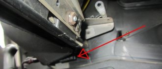
Protection of the Lada Vesta engine control unit
Protecting the OBD Vesta diagnostic connector from theft
https://lada-vesta-shop.ru/shop/v-pomosch-avtomobilistu/zaschita-diagnosticheskogo-razema-obd-ot-ugona.html – 3300 rubles.
As you can see, the price is not too high to refuse to purchase protective equipment. Of course, if desired and given enough time, the hijacker will still carry out his plans. However, his time is very limited, which means that the attacker will simply abandon his idea when he sees the comprehensive protection.
Do-it-yourself firmware
You need to be aware that all actions are performed at your own peril and risk. No one can guarantee that after installing the firmware yourself, the device will work correctly. To prevent this outcome, it is recommended to update the panel either at an authorized dealer or at specialized service stations.
The cost of such a service varies from 1,500 to 2,500 thousand rubles. This is much cheaper than buying a new shield to replace a damaged one yourself. For dismantling and reflashing, the warranty may be revoked if the procedure is not carried out by an authorized dealer. If you decide to update the software yourself, you will need to make a backup copy of the standard firmware, then prepare the necessary tools:
- A device for flashing Usbdm OSBDM V4.95 - can be ordered on AliExpress, the cost is approximately 600-700 rubles.
- Install drivers and software for Windows from the disk included with the programmer.
- Dismantle the instrument panel, peel off the factory seal, and remove the cover from the back.
- Open the programmer and move the checkbox to the 3.3V position - at this voltage you will not need an external power source.
- Connect to the dashboard and PC.
- On a computer or laptop, open the HCS12 Programmer program, select and click on the “Detected” item.
- Go to the “Target” item and select the folder with the location of the firmware, check the box next to the “Auto Reload” item, then click on “Detect Chip”. The programmer will determine the chip type automatically.
- Go to the “Security” tab and check the “Unsecure” box.
- In the “Advanced” tab, check the “Enable” box.
- In the “Device Operations” section on the “Target” tab, select the “Erase Selective” item - only the firmware will be replaced, the immobilizer data and mileage will be saved.
Now you can click on the “Program Flash” button - the firmware process will start. This will last a few seconds. After completion, when prompted by the program to connect the dashboard, click “No”. The flashing device can be turned off and the instrument panel replaced.
Protecting the OBD Vesta diagnostic connector from theft
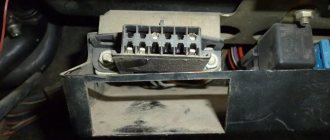
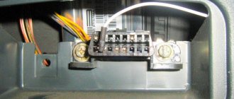
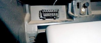
Protecting the OBD diagnostic connector from theft on the Lada Vesta is implemented a little simpler than protecting the engine control unit. In this case, you must be wary of connecting to the “brains” of the car directly from the passenger compartment - through the diagnostic connector, which is located to the left of the steering wheel, behind the plastic shield. This way, car thieves can start the car even without a key, bypassing all non-mechanical security measures.
The safe itself is a metal box with a bracket into which a diagnostic connector is inserted, after which the box is closed with a lid and screwed with 4 bolts. The peculiarity of such a safe is the unique configuration of the bolt, as a result of which it can only be unscrewed using the secret lock that comes with the kit. Moreover, manufacturers periodically change the layout of fasteners and secrets, complicating the work of car thieves. The wires are inserted into a small piece of corrugation, which is sealed with electrical tape.
It is also worth noting that the protection of the OBD Vesta diagnostic connector from theft is universal, unlike the ECU unit, so it will also fit other models, which is very important when there are several cars in the family.
The video demonstrates the installation process of both Vesta protective equipment.
Main malfunctions and their causes
- The device often fails due to mechanical damage. For example, the device received a strong blow or prolonged vibrations were observed, which caused cracks to appear on the soldered contacts and in other places.
- The controller overheats due to strong temperature changes. For example, in winter, some motorists start the engine at high speeds, trying to ensure it starts, which results in overheating of the ECM.
- Corrosion. Oddly enough, rust appears on the module due to frequent changes in air temperature and, as a result, the occurrence of large amounts of condensation.
- Depressurization. For this reason, moisture gets inside, which leads to failure of the device.
- Lack of communication with the control unit. Occurs after interference in the control system from the outside. This often happens when they try to “smoke” another car with a dead battery from one car. It is possible that while the engine is running the battery terminals are reset or the polarity is incorrect when connecting (the terminals are reversed). Less often, lack of communication occurs due to the starter starting without connecting power to it.
If the device is not working correctly or there is no connection at all, then you can notice this by the following signs:
- If there are obvious malfunctions, the Check Engine icon on the instrument panel does not light up or flashes intermittently at varying frequencies. You must first make sure that the light bulb is working properly and that it has power, and only then can you diagnose the ECU module.
- When connecting a diagnostic scanner to the connector, the latter produces incorrect data that raises serious doubts. Simply put, the data is completely different from what it should be. If the controller fails, the scanner may not connect at all.
- Engine malfunctions, tripping, the car does not start or starts with difficulty. However, there are no objective reasons for such phenomena.
- Misfires when the ignition system is in good condition.
- The fan in front of the radiator turns on spontaneously.
- For no apparent reason, fuses burn out, and different ones. Usually fuses blow due to voltage surges in the on-board network or a short circuit in the circuit, but if the diagnostics do not reveal such problems, then the problem is with the ECM.
- Pulses from the sensors do not arrive or arrive, but unevenly.
- Incorrect operation of the gas pedal. This is especially true for the electronic pedal: when the driver presses it, it either does not respond or does so late.
- Damage to the device body or contacts, for example, traces of burning on the terminal blocks.
Why is the check engine light on, what should I do next?
In a situation where the check light is on or flashing, the driver must listen to the operation of the mechanisms. If there are no failures or noticeable changes in the operation of the engine, there may be an error or failure of the Lada automatic system. Turn off the engine and start it again. If the check engine lights up again, some problems have arisen, and it’s not on for nothing.
Try to cope with the situation
Please note if there are any changes in the vehicle's performance. If the engine is operating in normal mode and the Vesta is driving normally, it does not twitch, there are no knocks, squeaks or noises, check the fuel tank cap
If it is not tightly screwed, or the integrity of the tank itself is compromised, the check may also catch fire.
Other problems are also possible - a malfunction of the oxygen sensor, low-quality fuel, a broken gas pedal, etc.
Diagnostics 2110
The tenth generation VAZ received a 12-pin diagnostic block. These began to be installed on cars as Euro-3 and higher standards were introduced.
Why is OBD2 not suitable for 10?
Frets of the tenth family received their own connection option for diagnostics. You cannot connect a standard international plug to it - intervention will be required.
The reason is that tens have a 12-pin connector. OBD2 has 16 pins.
Adapter for ELM327 and OBD2
News - you can assemble an adapter for tens. Need to:
- Connection diagram;
- 4 wires;
- New OBD2 format plug (if you don’t want to connect the wires directly to the scanner every time).
General questions about OBD2 on Grant
Let's look at questions about OBD2 on Grant - a diagram of what it is needed for.
How to use the connector
The main options for using OBD2 in Grant:
- Connecting a scanner to check the car and work with errors;
- Installation and connection of an on-board computer of the State or Multitronics type.
It will be useful to connect the on-board computer - this is how you can:
- control engine temperature;
- receive error codes immediately when they occur;
- force the cooling fan to turn on.
Diagnostic block diagram
The contact diagram of the block is shown in the picture:
The pinout of the block can be useful in the manufacture of adapters for OBD2.
Types and functions of the Lada Vesta ECU
The CBKE processes sensor signals and transmits commands to vehicle systems. His incorrect actions affect the operation of the machine.
The LADA VESTA sedan and Lada Kalina Cross cars are equipped with an M86 engine control unit manufactured by ITELMA.
ECU control functions:
TsBKE "Lada Vesta" controls the lights and power windows, takes into account the presence of a trailer hitch (traction device) on the car when braking.
Vesta with HBO has an ECU with firmware that supports two ignition timing modes. Also, a gas-powered car needs additional software for the control unit. The cost of making changes usually does not exceed 10 thousand rubles.
Why is it needed and how to reset the ECU
Sometimes the car loses power even with working equipment and jerks in gears. The reason may be incorrect operation of the Lada Vesta control unit. A reset will be required to return the device to normal.
- Install the OPENDIAG diagnostic program on your computer. Connect the scanner to the OBD2 connector. On the errors tab, reset the ECU settings followed by initialization. These operations are carried out with the ignition on.
- Next, adapt the throttle valve. After quiet clicks appear after 10 seconds, turn off the ignition and wait a few minutes.
- To train the ECU, you need to select a flat section of the road without heavy traffic. Warm up the engine to operating temperature. Perform 6-7 acceleration cycles with rpm of 4000 and engine braking to 1000.
- The unit is trained in 16 trips from starting the car to stopping the engine. During this period, you need to use good gasoline and drive the car with your usual driving style.
If during operation the car’s dynamics deteriorate, then the best way to reset the self-learning protocol of the ECU on the Vesta is to reset with initialization.
Source
We flash the Itelma M74 (Lada Granta) ECU with our own hands
In order to independently flash the Itelma M74 ECU, which, as we already know, is installed on the Lada Grant, you need to perform the following procedure:
- Disconnect the battery mass.
- Remove the ECU block. The connectors are disconnected like this:
- Let’s make a “spider” like this (I recommend signing the wires)
- We connect the connectors: Connector 1 (large) J1 - switchable voltage (K15) (12V) - second switch B2 - programming permission (12V) - first switch A4 - programming permission (12V) - first switch Connector 2 (Small) G2;G3; G4 - Ground (can be connected to any) H1; H2 - non-switchable voltage (K30) F2 - switchable voltage (K15) (12V) - second switch D2 - K-Line
- here's EL. diagram (many people write that they are flashing, but there is no diagram anywhere)
6. It is not recommended to apply voltage to all wires at the same time! It is necessary step by step through a double switch.
7. 4-And so the whole circuit is assembled and the KKL VAG-COM cord is inserted into the USB PC. Here is the voltage supply sequence
- Apply voltage (+12 V) to H1; H2 (throw the hooks onto the battery)
- Turn on the first switch (programming permission) B2 A4
- We launch the WinFlashECU program (-Select M74, -select the port number on which KKL VAG-COM hangs -it’s better to set the speed to the minimum)
- Next, turn on the second switch (which is on the “switch-off voltage”) F2 J1
- Communication with the ECU should appear (this is an indicator that the circuit is assembled correctly)
- Then we save copies of your “firmware and immo” on your computer, click
- Reading EEPROM and Reading ECU just in case (at the same time we check how everything works)
- code copying finished
- click ECU programming, look for the required firmware on your computer and download
ECU pinout on Lada Vesta
The electronic control unit of the M86 Lada Vesta car uses a 55 pin controller. List of sensors connected to the Lada Vesta control unit:
- throttle position;
- oxygen flow sensor;
- brake pedal position;
- crankshaft position;
- refrigerant pressure;
- gas pedal position;
- inlet air temperature;
- oil pressure;
- coolant temperature.
The electronic control unit also contains ground contacts, injectors, relays, and valves. The pinout of the VESTA ECU is specified in detail in the vehicle manual.
https://youtube.com/watch?v=RxjzBrfxj3U%3F
Access to the car's electronic unit is made through a special connector.
Assignment of OBD2 contacts in order:
- Reserve.
- J1850.
- Reserve.
- Weight.
- Signal equipment ground.
- J2284 CAN HIGH.
- Channel K.
- Reserve.
- Self-diagnosis codes - Service Check System.
- J1850.
- Reserve.
- Programming contact.
- Immobilizer.
- J2284 CAN-LOW.
- Channel L
- Power supply 12V.
Different communication protocols use their own sets of contacts. If output No. 7 is present and No. 2 is connected, then ISO 9141 and ISO/DIS 14230 are used. The presence of connection No. 7 indicates the SAE J1850 Variable Pulse Width Modulation or Pulse Width Modulation protocol. Diagnostics uses an OBD2 cable, part number J1962, for all communication protocols.
LADA VESTA. DIAGNOSTIC OXYGEN SENSOR (DOC) OF ENGINE 21129 WITH M86 EURO-5 CONTROLLER
content .. 120 121 122 123 124 125 126 127 128 129 ..
LADA VESTA. DIAGNOSTIC OXYGEN SENSOR (DOC) OF ENGINE 21129 WITH M86 EURO-5 CONTROLLER
To reduce the content of hydrocarbons, carbon monoxide and nitrogen oxides in the exhaust gases, a catalytic converter is used (see section 1.9).
The neutralizer oxidizes hydrocarbons and carbon monoxide, causing them to be converted into water vapor and carbon dioxide. The neutralizer also reduces nitrogen from nitrogen oxides.
The controller monitors the redox properties of the converter by analyzing the signal from the diagnostic oxygen sensor installed after the converter (Fig. 1.1-06). DDC works on the same principle as UDC. The UDC generates a signal indicating the presence of oxygen in the exhaust gases at the inlet of the converter.
The signal generated by the DDC indicates the presence of oxygen in the exhaust gases after the converter. If the neutralizer is operating normally, the DDC readings will differ significantly from the UDC readings.
The output signal of a warmed-up diagnostic oxygen sensor when operating in feedback mode, with a working converter in steady state, should be in the range from 590 to 750 mV and should not repeat the UDC signal. If a malfunction occurs in the circuits or the diagnostic oxygen sensor itself, the controller stores its code in its memory and turns on the alarm, signaling the presence of a problem.
The maintenance requirements for the DDC do not differ from those described above for the UDC.
LADA VESTA. CRANKSHAFT POSITION SENSOR (CPKV) OF ENGINE 21129 WITH M86 EURO-5 CONTROLLER
The crankshaft position sensor is installed on the oil pump cover (Fig. 1.1-07) at a distance of 0.9±0.5 mm from the top of the tooth of the drive disk mounted on the engine crankshaft.
The drive disk is combined with the generator drive pulley and is a gear with 58 teeth spaced at 6° pitches and a “long” synchronization cavity formed by two missing teeth.
When the middle of the first tooth of the toothed sector of the disk after the “long” cavity is aligned with the DPKV axis, the engine crankshaft is in position 114° (19 teeth) to the top dead center of the 1st and 4th cylinders.
- 1 - crankshaft position sensor
- When the drive disk rotates, the magnetic flux in the sensor's magnetic circuit changes, inducing alternating current voltage pulses in its winding. The controller determines the position and speed of the crankshaft by the number and frequency of repetitions
of these pulses and calculates the phase and duration of the pulses to control the injectors and ignition coil. The DPKV wires are protected from interference by a screen shorted to ground.
- If a malfunction occurs in the crankshaft position sensor circuit, the engine stops working, the controller stores a fault code in its memory and turns on the warning light.
- LADA VESTA. PHASE SENSOR (DF) OF ENGINE 21129 WITH CONTROLLER M86 EURO-5
Advantages of an auto scanner
What is the OBD diagnostic connector
“Scanmatik-2” was appreciated even by professional diagnosticians. Having tried this kit once, car enthusiasts were pleasantly surprised that for a relatively low price it allows you to work with a full fleet of domestic cars and an impressive part of foreign ones. When working with the diagnostic kit of this model, you can also use a wireless interface to connect the system to a computer (Bluetooth).
https://youtube.com/watch?v=Q5esXF84-Lk
The OBD-2 connector on Grant regularly supplies power to the diagnostic adapter. In extreme cases, the Scanmatik-2 adapter can be powered from the cigarette lighter. In general, the device is very convenient for performing diagnostic procedures yourself. It even has surge protection. If, for example, you apply current from the cigarette lighter when the system does not need it, nothing bad will happen.
Every device has pros and cons. Many car thieves know how to use the diagnostic connector for their own selfish purposes. As a rule, the diagnostic block is used by criminals to disable the standard immobilizer. A common solution to this problem is to replace the standard block with a “re-pinned” one, with a different arrangement of contacts.
The adapter consists of a “male” (fake connector) and a “female” (standard connector), which is previously removed. It will not be possible to connect standard diagnostic equipment to the new connector without such an adapter, but the chances of saving the car from theft are increased. That's all. Good luck!
Add to favorites
Seal
For me, the most difficult thing about a car is its “brains”. So I can fix everything myself, but I never get into this computer.
Well, at least the “brains” are not the same as, for example, in Toyota. Nothing can be done there at all without the permission of the BC.
It’s better not to get involved in this system yourself. It's easier to contact a specialist.
Oleg, essentially it’s like that in everything. If you don’t know something, then it’s better to run to a specialist.
BC STATE-1 stopped working. The diagnostician could be blocked or disabled. block? Anyone in the know, please tell me. Thank you.
Any system has “foolproofing”; since the 90s I have always repaired cars and computers (as far as understanding was enough) and have never broken anything, but I have found errors left by “professionals”
Please tell me where is the diagnostic connector for Lada Granta 2013?
Car driver test: what kind of driver are you? Car test for girls - you and the car Who is more important, you or your car?
Plug protection
Thieves can use the diagnostic connector to steal a car. They open the driver's door, connect their devices to the OBD, disable the protection, and start the engine without the ignition key. To protect the connector, you can block access to it.
The protection for the plug is like a steel box with holes for screws. It is made of two halves. One of them is removed to use the diagnostic connector. The protection is fixed through a bracket to the torpedo struts. The halves are fastened together with screws with heads for a secret key. Every year, experts develop new types of secret keys. This allows you to secure the product.
Protecting the OBD Vesta diagnostic connector from theft
Protecting the OBD diagnostic connector from theft on the Lada Vesta is implemented a little simpler than protecting the engine control unit. In this case, you must be wary of connecting to the “brains” of the car directly from the passenger compartment - through the diagnostic connector, which is located to the left of the steering wheel, behind the plastic shield. This way, car thieves can start the car even without a key, bypassing all non-mechanical security measures.
The safe itself is a metal box with a bracket into which a diagnostic connector is inserted, after which the box is closed with a lid and screwed with 4 bolts. The peculiarity of such a safe is the unique configuration of the bolt, as a result of which it can only be unscrewed using the secret lock that comes with the kit. Moreover, manufacturers periodically change the layout of fasteners and secrets, complicating the work of car thieves. The wires are inserted into a small piece of corrugation, which is sealed with electrical tape.
It is also worth noting that the protection of the OBD Vesta diagnostic connector from theft is universal, unlike the ECU unit, so it will also fit other models, which is very important when there are several cars in the family.
The video demonstrates the installation process of both Vesta protective equipment.
temperature sensor
The first thing I wanted to change was the temperature sensor readings. Initially, I didn’t like the algorithm of its work. In the range from 55 to 105 degrees it always shows 90. After riding Vesta for a year, I got used to it, but I would like to narrow the range and set it to 70-105. Why exactly like this? If the thermostat gets stuck and does not close completely, the antifreeze will circulate in a large circle. When heading out onto the highway, the temperature will drop to about 70 degrees.
But with the current range of 55-105 we simply won’t see this; the engine will operate in underheating mode
I don’t want to set the real temperature, since the needle will jump from 80 to 100 degrees and distract attention. These are still acceptable limits
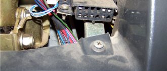
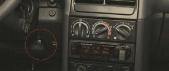
We connect the ELM to the diagnostic connector. On the Lada Vesta it is located near the hood release lever
It is important to insert it all the way
I read a lot of comments where people did not understand why the ELM does not connect to the phone. Then it turned out that this was due to loose insertion of the device into the connector.
Procedure:
- Turn on the ignition and launch the EcuTweaker program on your phone.
- Wait for the connection to be established between the phone and the ELM. The green indicator in the program will light up.
- Click on the magnifying glass icon.
- Select "All".
- Click "Meter Cluster".
- Click “PP_vesta” - Settings - Settings 2.
In the menu that opens, you can make the necessary changes.
If you want to see the real temperature, then change the “stepped” item to “linear” and click Write Model Tempengine. But I made a range change. In the corresponding column, instead of 55, I indicated 75, then saved with the same button.
Instructions for diagnosing VESTA via OBD2 connector with your own hands via a laptop or smartphone
Determine where the OBD2 connector is located
Determine which scanner is suitable for your car
The selection of a scanner (adapter) for LADA VESTA depends on the ECU model, as well as the needs of the diagnostician / car owner.
To select diagnostic equipment, use the calculator: “Selecting a scanner for Lada Vesta”
Download the diagnostic program for the scanner
The diagnostic adapter requires software that can be installed on a laptop or smartphone/tablet. Auto scanners with their own software shell and display do not require software.
To select a program for the adapter, go to the section: “Programs”
Use the instructions and carry out diagnostics
When you purchase an adapter, instructions are included with the adapter. More detailed instructions on diagnostic car scanners and descriptions of their operation are posted in the section: “OBD2 car scanner reviews”
Identify errors and decipher them
Error codes and their interpretation are displayed in the scanner program interface. You can also study the complete database of errors for your car in the section: “OBD2 error codes for Lada Vesta”
Make repairs according to the error code
The unit is repaired according to the decoding of the error (problem) or contact a car service to eliminate a particular malfunction.
Check errors again
A good choice for a novice diagnostician
Diagnostic adapters
Recently, diagnostic adapters that transmit information via Bluetooth to the phone have become widespread among car owners, as well as professionals. It can be used to read and erase error codes. The OBD-II V1.5 adapter is suitable for the Lada Vesta (the first part of the name is the type, the second is the version). The advantage of such a scanner is its low price, the disadvantage is that it is only suitable for a specific brand of car. However, for the owners of the Lada Vesta, the minus does not matter, but the pluses make you think - maybe they can buy it after all.
Instructions for replacing the block
The need to remove the control unit may arise for various reasons. For example, the problem may be the failure of the control device or the need to reflash it. It should be taken into account that flashing the ECU is a very important and responsible procedure that not every car owner can handle. Incorrect actions in the process of performing this task can lead to the fact that the unit becomes completely inoperable; accordingly, such an undertaking can cost the owner of the car dearly.
So, to dismantle the unit you will need to partially remove the center console.
To complete this task yourself, follow these steps:
First of all, you need to unscrew the bolts that secure the handbrake trim. Remove the cover from the gearbox control lever, and the facing panel must be dismantled. Next to the pedals, it is also necessary to unscrew the fixing bolts and dismantle the plastic lining. Lift the plug on the center console and remove it. Having done this, you will be able to see the connector for connecting the control unit via USB output. The fixing bolts of the fuse block must also be unscrewed, after which the connector can be removed from the installation site. The side bolts securing the console also need to be unscrewed. After completing these steps, you can turn off the cigarette lighter and raise the center console slightly. The ECU itself is located on its right side. In order to dismantle the control device, you will need to unscrew its fixing bolts, and then disconnect the block with the power wires
Do this carefully so as not to damage the connectors, otherwise problems may arise during further installation. After completing all these steps, the device can be removed. It is repaired, re-flashed or replaced, then reassembled in the reverse order
As you can see, in general the removal procedure is quite simple.
Installation features
To install a standard 2 Din radio, you do not need to purchase any additional elements. The product is placed in a standard frame and then connected to the connectors. The equipment is equipped with a small liquid crystal display, which displays indicators of the playback mode, song number, radio station frequency, as well as a number of other icons. Some Vesta cars use a head unit with a 7″ diagonal color touchscreen display. The audio device is also switched without additional devices.
A standard 1 Din radio is mounted instead of a plastic niche located in the center of the instrument panel.
To install a 2 Din radio on Vesta you need to:
- Prepare an adapter plastic frame that will allow you to mount the head unit in the instrument panel.
- The mounting niche located in the panel is designed for the use of products up to 157 mm in size. To install full-size radios, it is necessary to deepen the channel by cutting off the partitions.
- To provide access to the mounting socket, it is necessary to dismantle the decorative frame located around the instrument cluster.
- Then the front panel is removed along with the plugs and central deflectors of the microclimate system.
- After this, you can modify the niche with your own hands, using the head unit housing as a template. When cutting, be careful not to damage the wiring harnesses located inside the instrument panel.
- The front decorative frame is attached to the head unit housing with flat head screws.
- If the equipment is equipped with a rear USB connector, then the port is brought to its original location using an extension cable. It is possible to use a special module made in China, which combines USB and AUX connectors.
- Install the dismantled elements in their original places. If the steering wheel has standard control buttons, they are connected to the radio directly or through a special signal converter. The type of switching depends on the head unit model.
If the manufacturer or dealership did not install the speakers in their original places, then independent installation is required.
At the same time, you can improve the quality of sound reproduction by covering the inner parts of the doors and trim with a special material.
AMT 2.0 firmware Lada Vesta and Lada XRay
Programming the new AMT 2.0 mode is only possible in conjunction with programming the updated ECU firmware.
The updated AMT 2.0 firmware for Lada XRay cars is temporarily unavailable.
When the gas pedal is released, the operation of the AMT goes into the “creeping mode” phase, that is, the clutch does not disengage at the second and first speeds until the lower idle threshold.
Switching between 1st and 2nd, 2nd and 3rd gears occurs 30% faster and the shifting itself is faster, softer, and does not lead to jerks and jolts.
A winter mode has appeared (the ability to start from 2nd gear in manual mode).
AMT operation in the new AMT 2.0 firmware is not a full-fledged analogue of an automatic transmission:
it is impossible to make a car with AMT stand still on an incline without a brake; it is impossible for a car to crawl on a steep incline without gas; The condition of the clutch disc and the settings of the actuator are very important for AMT operation; When the doors are open or the handbrake is raised, it is impossible to engage the gear.
Vesta error codes - decoding and designation
To properly understand the essence of the problem, you need to know how the serial error number is deciphered. The screen of a third-party device usually displays a five-digit code, where the first part is:
- B – body systems are damaged;
- C – interruptions in the stability of the suspension and chassis;
- P – incorrect functioning of the electronics of the power unit or gearbox;
- U – the data exchange bus is out of order.
Next comes the first digit:
- 0 – SAE catalog number;
- 1-2 – standard serial number;
- 3 – reserve.
- 1-2 – air or fuel supply devices;
- 3 – ignition;
- 4 – catalyst problems;
- 5 – incorrect idle speed;
- 6 – problems with the computer;
- 7-8 – gearboxes for automatic or manual.
The last element of the code indicates the serial number of the error.
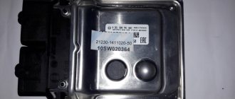
ECU characteristics
We suggest that you familiarize yourself with all the necessary information regarding the operation of the unit below.
Where is the block located?
The engine control unit of a Lada Kalina, Kalina 2 or Granta car is located near the center console of the cabin. To get to it, you only need to remove the panel. As you know, domestic engineers have always been famous for their senseless and “merciless” decisions in terms of assembling cars, so the location of the ECM unit was chosen thoughtlessly. In practice, such a device often fails as a result of moisture getting on it, so many car owners decide to move the unit so that it can stand in a safer place.
ECU location
Features of work
So, the control unit of the electronic engine control system is designed to monitor the status of all components and transmit impulses to the motor. The ECM itself transmits information from various sensors designed to monitor the operation of a particular mechanism or system. Information is processed without interruption, as a result of which all nodes can work harmoniously. In addition, the ECM controls systems designed to control the level of toxicity of exhaust gases.
The data collected by the Lada Grant or Priora ECU represents different characteristics. For example, the mass air flow regulator controls the fixation of mass flow by the motor - the more air the power unit consumes, the better its dynamics will be. But if the normalized indicators are exceeded, this will lead to excessive consumption of gasoline; accordingly, timely checking of the parameters will prevent possible malfunctions.
In addition, the ECM unit records the following information:
- about the position of the crankshaft and camshaft;
- o temperature of antifreeze in the cooling system;
- about the temperature of the intake air;
- about the voltage level in the car's electrical circuit;
- about the possible content of impurities in exhaust gases;
- about the speed of the vehicle;
- about the oscillatory amplitude of the body (video author - Low Customs).
In accordance with the information received, the “brains” check the performance of the main systems, including the diagnostic one. As for the latter, it is one of the most significant, since if a particular malfunction is detected, it is this system that will be able to notify the car owner about the problem. Information about breakdowns is transmitted through the appearance of a warning light on the dashboard. Regardless of the model of the ECM, the device will store error codes in its memory, which will allow the car owner to determine the malfunction as accurately as possible. Such information may be required if the device pinout is needed.
It should also be noted that the ECU has several types of memory:
- The first type is PROM. This memory contains all the necessary control circuits, and this memory also records commands in a certain sequence. The EPROM contains data on the calibration of various processes, which depend on the power of the power unit and its type, the weight of the vehicle as a whole and other factors. It should be noted that this type of memory does not depend in any way on voltage sources, so even if the device is not powered from the network, all the information in the memory will still be saved.
- The second type is RAM. This type of memory must always be powered from the on-board power supply, otherwise all information about diagnostic codes will be deleted. This block stores all the data that the ECM needs for calculations.
- The next type is EPROM, which literally stands for electrically programmable memory device. The main purpose of this block is to store combinations for the immobilizer. The absence of these passwords in memory or their discrepancy with the data on the key will make it impossible to start the engine. It should be noted that in this case the data is also stored permanently (the author of the video is Andrey Pomazanov).
lada news
Website support and promotion - Avada.ru
We draw your attention to the fact that all information presented on the site is for informational purposes only and under no circumstances constitutes a public offer as defined by the provisions of Article 437 (2) of the Civil Code of the Russian Federation. By providing your personal data and using this website, you consent to the processing of your personal data and accept the terms of their processing
Privacy Policy
By providing your personal data and using this website, you consent to the processing of your personal data and accept the terms of their processing. Privacy Policy
To improve the convenience of using the site and ensure its correct operation, AutoHERMES uses cookies. These files contain data about your previous visits to the site. Cookies do not identify your personal data. All information is strictly confidential. If necessary, you can disable cookies using your browser settings.
It’s clear what to do, let’s get to work!
We purchase the following components in the store:
Low frequency amplifier microcircuit TDA7560, without a letter code at the end of the name. Cost about 450 rub. Electrolyte with a capacity of 10,000 uF at 25 V with an operating temperature of 105 degrees. The radio is very hot when working. Cost about 100 rubles. Film capacitor with a capacity of 0.47 µF at 250 V, type K73-17. Cost about 20 rubles. We bought the components, remove the radio and take it to the desktop, where we will do the modernization.
This is what the radio looks like on the desktop, where we will solder the microcircuit and connectors.
And this is a marking plate, if anyone doesn’t know.
Let's disassemble the radio! This process did not cause any difficulties; we unscrewed the visible screws and that was it.
This is a view of the PCB with the top cover removed.
We disconnect the cable from the board and unscrew it from the case.
This is what the printed circuit board looks like.
And we will change these elements. The chip is circled in red, the electrolyte in yellow.
Recommendations
Comments 52
Hello. Tell me how you became friends with Elm.
Yes.elm I only have the bluetooth version
In addition, there was a +12 output from the reversing light in the camera wire (a separate wire), it was connected to the corresponding wire of the radio. - - - with which? What was the name of the wire?
The picture of the radio pinout shows the BACK wire. +12 reverse is supplied to it, this locks all functions of the radio and only the image is displayed
Doesn't turn on when engine is off
In what position is the ignition key?
in off (Ignition off)
If you connected everything correctly, this is correct. This is not a paradox. If you want constant operation of the MMC, then you need to power it not using + 12V from the ignition switch (ACC), but by taking the constantly hanging voltage used to power the MMC settings memory. It's clear?
From which contact do you supply power to the antenna amplifier? Lada westa sw cross.
Signed on the picture. Take from C4
Standard cameras have appeared in Westashhop. Price 5K
My friend, if the radio has only one wire to control the steering wheel, then how?
China radio, wire 10 in the photo
Connecting the three-wire interface of the multifunction steering wheel to the (one) two-wire interface of the radio The standard resistive interface of the radio control buttons on the steering wheel of a car usually contains three wires: KEY1(SW1), KEY2(SW2) and KEY GND. At least for Toyota, this is the case if the radio control is not implemented via CAN BUS (we will not consider this case). In radios manufactured in China, there are usually also three separate wires allocated for this: KEY1, KEY2 and KEY GND. In this situation, we connect the corresponding wires to each other and configure the necessary buttons in the radio.
But it happens that the radio has only one wire dedicated to the multifunction steering wheel. In this case, you can try the following scheme: connect the KEY GND wire from the steering wheel to the body of the radio, the brown (usually) wire KEY1(SW1), which controls the volume and switching tracks, to the KEY wire of the radio, and the gray KEY2(SW2), which controls the radio modes MODE, through a 5.1 kOhm resistor we connect to the brown wire KEY1 (SW1). After that, we go to the radio settings and check the operation of the resulting circuit in the Steeering wheel control settings, setting up the buttons we need. In theory it should work
Instructions for diagnosing VESTA via OBD2 connector with your own hands via a laptop or smartphone
Determine where the OBD2 connector is located
Determine which scanner is suitable for your car
The selection of a scanner (adapter) for LADA VESTA depends on the ECU model, as well as the needs of the diagnostician / car owner.
To select diagnostic equipment, use the calculator: “Selecting a scanner for Lada Vesta”
Download the diagnostic program for the scanner
The diagnostic adapter requires software that can be installed on a laptop or smartphone/tablet. Auto scanners with their own software shell and display do not require software.
To select a program for the adapter, go to the section: “Programs”
Use the instructions and carry out diagnostics
When you purchase an adapter, instructions are included with the adapter. More detailed instructions on diagnostic car scanners and descriptions of their operation are posted in the section: “OBD2 car scanner reviews”
Identify errors and decipher them
Error codes and their interpretation are displayed in the scanner program interface. You can also study the complete database of errors for your car in the section: “OBD2 error codes for Lada Vesta”
Make repairs according to the error code
Self-diagnosis
To diagnose all ECUs, electronic scanners are used that can be connected to portable devices - laptop, tablet, smartphone.
Scanners
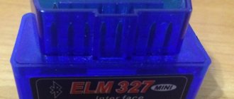
The most common devices for self-diagnosis of Lada Vesta are scanners with an ELM327 chip, versions 1.5 and 2.1. Devices compatible with OBD2:
- Scan Tool Pro;
- ScanMatic2;
- Launch CRP229.
The first two models are budget models, most in demand among car owners for self-diagnosis. Connect via an adapter to a laptop computer or smartphone with installed software and a USB output. A Bluetooth connection is also used. The cost of the equipment does not exceed 2000 rubles.
Scan Tool Pro. Photo source: drive2.ru
The Launch CRP229 autoscanner comes with a DBC adapter and includes a tablet with memory for installing software and a rechargeable battery. The price of a set of equipment is 19,000 rubles.
Launch CRP229. Photo source: youtube.com
You can buy equipment in specialized stores and on the Internet through Aliexpress. In the appendix to the operating instructions for auto scanners there is a decoding of common error codes.
Adapters
Types of adapters for connecting car scanners via OBD:
- VAG – USB port;
- ELM – wireless for connecting via Bluetooth or wi-fi.
Along with the adapters, software for portable devices is sold, compatible with the Android, IOS, Windows, and Mac platforms. Car enthusiasts can independently download the software for laptops and smartphones.
Software
To diagnose Lada Vesta via ELM327, there are several programs compatible with OBD2. The most popular, error-free and crash-free software for Vesta is OpenDiag. Also used:
- TorgiePro – application for use on Android;
- AutoEnginuti – program for IOS and Windows;
- PCMScan – for laptop computers.
Most software and drivers for adapters are available for download on specialized websites and online stores. It is recommended to use certified software.
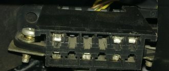
Equipment connector
Vesta diagnostic equipment is connected via adapters to a special 16 pin connector (has 16 contacts). It is located to the left of the steering column under the dashboard, next to the lever that opens the hood. The block socket does not have a plug. Until 2006, AvtoVAZ models had 12 pins (12 contacts) in OBD2.
Solution
It is worth noting that, unlike Solaris, it is a little more difficult to access the Vesta control unit, since it is covered on top by an air filter duct, and dismantling it will take time to get to the unit itself. However, there is nothing to rely on the air filter.
Naturally, all this can be avoided if the ECU is reliably protected. That is why installing 2 security measures in Vesta seems more than justified:
- Protection of the Lada Vesta engine control unit;
- Protection of the OBD Vesta diagnostic connector from theft (universal).
Buying these two accessories significantly increases your chances of emerging victorious in a fight with a car thief.
With such protection, the owner of Vesta can sleep much more peacefully.
Location
To carry out diagnostics on a computer, you must first find where the diagnostic connector is located. It serves to connect control devices and is connected to the electronic unit. The ECU diagnostic socket is located on the edge of the plastic panel under the mounting block and steering column. It is not closed and is easily accessible for use. But this only plays into the hands of the hijackers.
Methods for diagnosing ECUs and errors on Lada Vesta via OBD2
Let's look at examples of analyzing machine systems in different ways.
Check Engine light on Vesta?
Detailed article on the causes of Check Engine and how to clear the Check. If your Check Engine light comes on, read this article immediately. The material explains what a Check Engine is, what to do if it appears, and how to remove this error yourself.
Is the Check Engine light on?
TOP 15 reasons why the Check Engine light comes on and ways to solve the problem. Read the article to solve the Check Engine problem.
To enter the BC diagnostic mode, hold down the top key and turn on the ignition.
Reviews of diagnostic scanners for LADA VESTA
Read detailed articles on the review of car scanners, including those compatible with LADA VESTA.
Reviews of OBD2 diagnostic car scanners
This section provides descriptions of diagnostic scanners and adapters. Before purchasing a scanner for your car, it is recommended that you read reviews of the most popular equipment models.
New software is written using programmers. There are open and closed ECUs.
- In a diagnostic way. Without removing the ECU from the vehicle via the diagnostic connector using flash loaders and a program such as Combiloader.
- Work via BSL mode of the ECU processor. With this method, programming the ECU is carried out by removing the latter from the car using bootloaders that work with the ECU processor via BSL mode.
The scanner is suitable for Vesta
This is what a Chinese car scanner with Bluetooth looks like
If you have a domestic-made car, then you should choose firmware version 1.5, because the adapter with firmware 2.1 does not work with the OpenDiag Mobile program, which is designed specifically for diagnosing domestic cars. In firmware version 2.1, some protocols are processed incorrectly.
If the adapter has firmware 1.5, then it will work with foreign cars after 1996 that support the OBD-2 standard, and with domestic cars through the OpenDiag Mobile program. Machines after 2008-2009 work reliably on an adapter with firmware 2.1.
Before 2008-2009, it happens that if a car uses a non-standard diagnostic protocol, then 2.1 may not connect to your car. Therefore, if you have a car from 1998, then it is better to choose an adapter with firmware version 1.5.
First, let's connect the adapter with firmware version 2.1. To do this, insert it into the diagnostic connector of the Lada Vesta and turn on the ignition of the car. Go to settings on your smartphone. Select Bluetooth, turn on the search for a new device, click on the found device.
We ask for a password, after which you need to enter the standard password for the Bluetooth adapter. Usually this is 1234 or 0000. After this, exit the Bluetooth menu and find the OpenDiag program. Vesta will also be diagnosed.
When is diagnostics needed?
While the car is moving, when the driver does not notice any malfunctions, the icon (chek), schematically depicting the engine, may light up on the tachometer dial. This means that one of the systems has failed.
Check icon. Photo source: drive2.ru
In such a situation, there is no need to panic; perhaps this is a short-term equipment failure, then the chek lights up for a few seconds and does not appear again. If the error indicator blinks or is constantly lit, you must contact a service or dealer center for diagnostics. If you have the skill and necessary equipment, you can check it yourself.
Options
The electronic engine control device for the Lada Vesta is Itelma M86. All other nodes are controlled by CBKE. Communication with vehicle systems is carried out via the CAN data bus. In addition to the standard installed components, the ECU interacts with the following devices:
- alarm;
- GPS tracker.
Itelma block. Photo source: drive2.ru
The main requirement for connection is the ability to work using a protocol compatible with the engine ECU.
Through the TsBKE block it is possible to diagnose the main components of the car:
- automatic transmission;
- anti-lock braking system ABS;
- dashboard;
- electric power steering.
The condition of electrical accessories and airbags is monitored. The developers have provided more than 50 parameters by which you can control the operation of the devices. The owner's manual lists about a hundred common error codes that the engine ECU can report. There are a total of 3,000 faults that can be identified by diagnostics.
Electronic control systems are monitored and adjusted using the values approved in the manual. Based on the data received from the scanner, the following is determined:
- precise engine speed at idle and under load;
- coolant temperature;
- fuel consumption;
- on-board electrical network parameters.
The exact total mileage of the car is determined by the trip computer. The data received from the scanner may differ from the instrument readings. During diagnostics, you can clearly assess the technical condition of the car and receive graphic reports.
Description and technical specifications
Since March 2014 Instead of the DST-14 scanner-tester, its new modification DST-14T is being produced.
DST-14T differs only in the housing and the location of the connectors; the software and functionality have not changed. The diagnostic connector is now located at the bottom, the USB connector at the top.
Software support for the previous DST-14 model is retained in full; all software is suitable for both DST-14 and DST-14T.
The discontinued DST-14 differs from the DST-14T only in its housing and the location of the connectors, software and functionality have not changed.
DST-14 software support remains in full; all software is suitable for both DST-14 and DST-14T.
DST-14 is recommended by AvtoVAZ as a dealer scanner for VAZ cars.
Software. Updating the software of the scanner tester DST-14.
DST-14 software support remains in full; all software is suitable for both DST-14 and DST-14T.
The latest versions of software modules are on the NTS website. On our website you can view the detailed composition and download the software modules of the DST-14 tester scanner.
Procedure for updating the software: Software modules are stored in the Program Files folder of the tester scanner and have the corresponding extensions: diagnostic .d14 and system .sys Updating the DST-14 software (software modules) can be done at dealers or independently. Software updates are performed via USB using a standard USB cable. To update the software, you will need a scanner tester DST-14, a standard USB cable and a power supply (from the main package), a computer with a USB 2.0 port, an Internet connection and basic skills in working with a computer, programs and files. The DstManager program allows you to automatically check for updates for DST-14, download modules from the website, unpack from the archive and install them into a tester scanner. To operate the program, you need Internet access and a computer connection to the DST-14. If, when you start the DstManager program, there are no modules marked with arrows in the list, this means that the latest versions of the modules are currently installed in your DST-14. From January 20, 2022, the sales policy for update modules for DST scanner-testers has changed due to the situation on the sales market. Scanner-testers DST-14T are sold with the “all inclusive” option until 2015 (until December 31, 2014). All DST update modules released in 2015, 2022 and later will be sold separately. Updates to fix errors in already purchased software are available to users free of charge.
When purchasing a new update module, the user is sent an activation key. Software modules already authorized by the activation key will work indefinitely. As development progresses, new software modules are posted on the NTS website.
Video - Installing Applauncher and Easy Connected
From the moment I bought the car, the plan was to install MMC on Android, I like it better than WinCE. For installation, I chose an inexpensive device, which in terms of functionality and quality suited me quite well - ACV 7610 (RUB 12,000).
Total about 15,700 rubles. I found the pinouts for the luxury Lada on the Internet, and the pinouts for the radio were in the manual.
Let's get to work. We will not cut the original wiring; we will use donor adapters for switching. First of all, we make a male-to-female ISO A and B adapter. To do this, we use the ISO A and B connectors with wires from the radio kit and the purchased ISO A and B male connectors. We connect part B, which is responsible for the speakers, one to one, there are no problems here. The most important part is A, where the power and controls sit. You have to be careful here.
On the Lada connector, power is supplied from the battery to A4, power from the ACC ignition switch is supplied to A7, and on MMC ACV it is exactly the opposite: A7 and A4. They need to be connected correctly! For what? - Further. In order to prevent the radio from turning off when starting the engine, we attach a simple circuit to the ACC wire.
We select the capacity based on the desire for the duration of operation of the radio without an ignition key. With a capacity of 10,000 μF, I was able to operate for 3 minutes, with a capacity of 2,200 μF - 45-50 seconds, I didn’t experiment further, but the logical series can be continued. If you cross-connect (see above), it will not work.
About connecting the buttons on the steering wheel. In connector A of the radio there are three wires A1, A2, A3, labeled Key1, KeyGND, Key2, respectively. We use them to connect to C16, C19 and C18, respectively, in the blue Lada block. We cut and connect in the donor adapter! C16 and C18 are two white wires, they can be connected to A1 and A3 in any combination, C19 is black, ground, black with black) Next, solder 100 resistors to wires C13 (blue), C15 (white-blue), C14 (white-red), 220, 330 Ohms, respectively, we put them in heat shrink, solder the other ends together and solder them to the black wire C19, we insulate everything.