Tuning cylinder head VAZ 2112 2106 + review of VAZ engines
Well, I'll start with the standard sizes of the cylinder head of a VAZ.
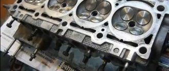
Classic cylinder head or front end 8 bore diameter 29 inlet 31 seat 26 exhaust 27 seat. valve 36 x 32 leg diameter 8, valve size - can be killed without problems) Naturally, the cutter on the 28 intake channel does not fit despite its diameter of 29. Plus, the classic has tides in the channel under the guides and the exhaust is more clamped than on the 8-piece front end . Cylinder head 2112 shesnar bore diameter 34 inlet 2 seats 25 exhaust 31 2 seats 21 valves 29 x 25 leg 7 valve size not very meaty
Standard channels have a serious roughness, which as a result of operation has a positive effect on carbon formation and a decrease in the diameter of the channel. On average, the soot layer in the channel reaches up to 4 mm or even more. Carbon deposits on the valve also sometimes resemble coral reefs. Another note from history, the cylinder head of the VAZ classic was created for the 2101 1.2 engine. For this engine, the cylinder head was suitable, small volume, small channels and valves. The same thing happened with the cylinder head 21083, created for the 1.1 21081 engine. However, instead of creating new cylinder head, the manufacturer simply created new blocks and slightly modified the cylinder head. The increase in power shows that the 2101 1.2 engine has a power of 64 hp, which is equal to 53 per liter, the 21011 1.3 engine has 69 hp, which is equal to 53 per liter, the 2103 1.5 engine has 73 hp, which is equal to 48 per liter, the 2106 1.6 engine has 76 hp, which is equal to 47 per liter, engine 21213 1.8 has 80 hp, which is equal to 44 per liter. It was according to this logic that I chose block 21011 1.3, and RS of course) That is. if the cylinder head increased along with the cylinder head, 1.6 would have 84 hp, and 1.8 95 hp, which is not bad)) Well, it is clear that the larger the volume, the less liter power, despite the fact that there is more power. The increase in torque from the bottom is a separate topic)
Now about the flow of the cylinder head, the narrowest place in the cylinder head is the valve seat. Let's stupidly add up the numbers VAZ 8 ve diameter of the inlet saddle 31x4 = 124 minus valve legs = 92 VAZ 2112 16 ve 25x8 = 200 minus legs = 144 You can immediately see how much 16 valve engine is in front. Although the shesnar has many of its own weaknesses, which do not give it such a great advantage in real life. The engine power of the VAZ 2112 1.5 is 90 hp, which is equal to 60 hp per liter, which is essentially not much relative to the 53 hp obtained half a century earlier))) Considering the huge differences in engines, a large compressor is 10.5 versus 8.6, 16 bugs versus 8, injector versus carb, it turns out that the 8 bugs engine also has quite a bit of potential.
Now about tuning these engines. The cylinder head of a classic VAZ can be bored to 36 intake channel 34 exhaust, seat to 34 x 30 valve to make it easier to reduce the valve stem.
The front cylinder head of a VAZ can also be bored when filling in the oil channel.
The cylinder head of a VAZ 2112 can be bored if without fanaticism)) 37x34 channels of the seat are expanded to 27x23 valves, lighten the legs, sharpen them to 6
Now let’s recalculate the result obtained: cylinder head VAZ classic saddle 34x4 = 136 minus legs = 108 cylinder head VAZ shesnar saddle 27x8 = 216 minus legs = 168 The difference has become even greater, but the channels have moved closer to each other. and the difference can be compensated by lifting the valve, and by larger valves. For which, unfortunately, a 16-cylinder engine is ideally suited, standard saddles can be turned to 32 by 27 with the replacement of valves, and on the classics it is necessary to change the saddles.
My personal opinion regarding the choice of motor. I consider swapping gear into classics not worthwhile, more fashionable than practical. Especially if the gear is standard and even minor tuning will not give a normal result. A good topic for a gearbox is pipe charging, but the cost of subsequent repairs is not commensurate with the result obtained. It is easier to prepare a classic motor and then replace the BC in case of destruction. Why is 8 valve better? Firstly, the cost of motors clearly varies, as do maintenance and repairs. The 8 valve is simpler and, as a result, more reliable, the drive chain is RV, the pushers are solid, the timing belt is lighter (one shaft, 8 valves, 16 springs)). The 8 valve is easier and cheaper to tune, has a significant service life, and it’s just as easy and cheap to find a replacement. The atmospheric version of the engine is quite simple and cheap to assemble, using either motorcycle carbs, or Dellorto, Webers, Solexes or whatever))) In this case, you don’t need to look for expensive boosts, the engine will not eat like a horse and fail when you press the gas to the floor , setup is cheaper and easier (yes, yes, easier!). The output power will of course be less (not significantly and that’s not a fact), but the price will not be commensurately less)) The 8-valve turbo option is again simpler and cheaper, you can assemble a turbo on a carb and blow it with the mixture. Which will cost nothing. If executed correctly, the resource will be quite large. But the power obtained from an 8 valve turbo cannot be compared with the power of a 16 valve. Here the gearbox fully opens, but the difference in price is cosmic) Among the 8 valves, the best option is a combination of a good RS with a small volume. Because, as I already said, the 8 valve head is designed for a smaller volume. Those. It turns out that a large crankshaft and a large volume only spoil the matter. You can, of course, improve the situation by increasing the channels and valves, but this is my logic. Why correct the situation if it is easier to get the maximum from a small business center. After all, what happens. If you cut the cylinder head to 36X34, then for a 1.6 engine it will be almost standard (by the standards of foreign cars). And for a volume of 1.3 cylinder head, 36x34 will be excellent, taking into account the increasing efficiency with speed from a high RS of about 2, you can get an excellent result for a torsional motor.
With an 8-valve front-wheel drive, you can also get a decent result with less hassle than with a gearbox. I have seen more than once how much effort, time and money people spent on converting it into gear, and the result was a car with almost standard dynamics of a regular 2112. And then even greater costs and hemorrhage with tuning the gear and bringing the dynamics to acceptable. Shafts receiver throttle program spark plugs boring modules. And then you end up with a guzzling, not very reliable car with an engine of 150 hp max. I just want to tell people to install a 406 engine; it has 150 hp in stock))) If, of course, you make a gear for the throttle on large valves, evil shafts, then the result will be excellent. But the ratio of investment and result will not be justified, and again, the expense.
Removing the seat
First, let's look at what not to do, although some automotive garage gurus recommend doing just that.
-valve welding + knocking out
https://youtube.com/watch?v=mEe3wNJwuKQ
First, the old unnecessary valve is adjusted to the dimensions of the seat, inserted onto the seat and the valve is welded to the seat. While it is still warm, knock out the valve and it comes out along with the seat. Due to the different expansion of metals - steel and aluminum - the tension decreases; when it cools down, it will not be so easy to come out.
Why shouldn't you do this? During welding, the entire head heats up and it will certainly move, it will become crooked and in addition to this, hidden cracks will open where there were internal stresses in the metal (and they exist in any case). Then you will wonder why my head suddenly turned out to be pierced.
The best way is to bore the valve seat on a machine until it becomes the size of foil and jumps out of the seat hole. But... this cannot be implemented in a garage due to the high cost of the equipment, and not every village will have such a machine. Therefore, let’s consider another method, easy and safe, and can be implemented in any garage.
Choosing garage technicians: a simple and safe way
Using a milling cutter, grind the saddle all the way through one edge. The seat will weaken, lose tension and jump out of the seating hole on its own, without even having to sharpen it through, reaching the seating plane, when a little less than 0.5 mm of tension remains, the tension is no longer enough to hold on. By opening the ring, the saddle will no longer be able to resist.
A drill cutter is sold in any hardware store and costs no more than a drill, which is why this method is so affordable.
Now that the saddle is out, we need to think about what we are going to put in there.
Cylinder head and valve mechanism of VAZ 2101 Zhiguli
3.11.1 Cylinder head and valve train
Main dimensions of the cylinder head, valves and guide bushings The cylinder head is common to four cylinders, cast from an aluminum alloy. It is unified, i.e. the same for engines 2101, 21011 and 2103. Cast iron seats and guides are pressed into the cylinder head.
3.11.2 Device features
Main dimensions of the cylinder head, valves and guide bushings The cylinder head is common to four cylinders, cast from an aluminum alloy. It is unified, i.e. the same for engines 2101, 21011 and 2103. Cast iron seats and guides are pressed into the cylinder head.
3.11.3 Removal and installation on a vehicle The cylinder head is removed from the engine on a vehicle if the engine itself does not need to be removed to eliminate the malfunction or if it is only necessary to remove carbon deposits from the surface of the combustion chamber and valves. Removal PERFORMANCE ORDER 1. Drain the coolant from the radiator and the central unit.
3.11.4 Disassembly and assembly
Valve mechanism parts 1 – valve; 2 – retaining ring; 3 – guide sleeve; 4 – oil deflector cap; 5 – support washer of the outer spring; 6 – support washer of the internal spring; 7 – internal spring; 8 – outer spring; 9 – spring plate; 10 – crackers; eleven - .
Springs
Basic data for checking the outer valve spring
Lever spring check diagram
A – free size; B – dimension under load
1. Make sure there are no cracks on the springs and whether the elasticity of the springs has decreased, for which check the deformation of the springs under load (Fig. Basic data for checking the outer valve spring, Fig. Basic data for checking the internal valve spring, Fig. Diagram for checking the lever spring ).
2. For lever springs (see Fig. Lever spring check diagram) size A (spring in a free state) should be 35 mm, and size B under load 51–73.5 N (5.2–7.5 kgf) - 43 mm.
Classic VAZ valve diameter
Moderator: Randall
Installation of enlarged valves
Unread message by VintoreZ » Sun Aug 01, 2010 23:49:36
Re: Installing larger valves
Re: Installing larger valves
Unread message Violent » Mon Aug 02, 2010 5:59:50 AM
Re: Installing larger valves
Unread message from VintoreZ » Mon Aug 02, 2010 10:03:05
Re: Installing larger valves
Unread message byran » Mon Aug 02, 2010 10:27:51
Re: Installing larger valves
Unread message from VintoreZ » Mon Aug 02, 2010 10:39:54
Re: Installing larger valves
Unread message byran » Mon Aug 02, 2010 10:55:40
Re: Installing larger valves
Unread message by VintoreZ » Mon Aug 02, 2010 11:12:44
Re: Installing larger valves
Unread message byran » Mon Aug 02, 2010 11:23:38
Re: Installing larger valves
Unread message by Lihoi78 » Mon Aug 02, 2010 11:33:46
Re: Installing larger valves
Unread message from VintoreZ » Mon Aug 02, 2010 11:44:54
Re: Installing larger valves
Unread message byran » Mon Aug 02, 2010 11:55:56 AM
Re: Installing larger valves
Unread message Violent » Mon Aug 02, 2010 17:56:42
Re: Installing larger valves
Unread message _Kolyan_ » Wed Jul 20, 2011 21:02:43
- Classic car forum
- ↳ Useful improvements to the classics
- ↳ Our classic iron horses
- General auto forum
- ↳ Operation and maintenance of our vehicles
- ↳ Tires and wheels
- ↳ Car protection from theft
- ↳ Car audio
- ↳ Auto gadgets
- ↳ Autoworld
- ↳ Tips and secrets
- Other cars of the VAZ family and more.
- ↳ “Chisels” from 2108 to 2115
- ↳ From tens to priors VAZ-2110 - VAZ-2170 and their modifications
- ↳ Kalina and Granta VAZ-1117 VAZ-2190 and their modifications
- ↳ Niva, Niva-Chevrolet and other 4x4
- ↳ Foreign Forum
- ↳ Domestic auto industry and others
- Classic auto repair shop
- ↳ Engine
- ↳Transmission
- ↳ Chassis
- ↳ Brake system
- ↳Electrics
- ↳ Injector
- ↳ Body
- ↳ Repair experience - miscellaneous
- ↳ Tuning
- Private advertisements
- ↳ Selling
- ↳ Buy
- ↳ I'll give it away
- ↳ Services
- Miscellaneous
- ↳ Number informers
- ↳ Classicist at the computer
- ↳ Our hobbies
- ↳ Our tool
- ↳ Meetings of forum members
- ↳ Travel, trips, events.
- ↳ Chat
- ↳ Smokehouse/floodhouse
- ↳Humor
- ↳ Community
- ↳ Entertainment (18+)
- Technical department
- ↳ About the site, forum and photo gallery
- ↳ Our symbols
Who's at the conference now?
This forum is currently viewed by: no registered users and 1 guest
- List of forums
- Time zone: UTC+01:00
- Delete cookies
- Users
- our team
Powered by phpBB® Forum Software © phpBB Limited
Article: 21080-1007055-00, additional articles: 21080100705500, 2108-1007055
Order code: 010583
- Maybe they will be useful for you
- show more
- Passenger cars / VAZ / VAZ-21091 drawing
” href=”/catalog/vaz-3/legkovye_avtomobili-30/vaz_2109-9/mehanizm_gazoraspredelitelnyiy-81/#part32138″>PusherEngine / Gas distribution mechanism
- ” href=”/catalog/vaz-3/legkovye_avtomobili-30/vaz_2110-10/mehanizm_gazoraspredelitelnyiy-101/#part40330″>PusherEngine / Gas distribution mechanism
- ” href=”/catalog/vaz-3/legkovye_avtomobili-30/vaz_2112-12/mehanizm_gazoraspredelitelnyiy-101/#part48946″>PusherEngine / Gas distribution mechanism
- ” href=”/catalog/vaz-3/legkovye_avtomobili-30/vaz_1111__oka_-16/mehanizm_gazoraspredelitelnyiy-53/#part66790″>PusherEngine / Gas distribution mechanism
- ” href=”/catalog/vaz-3/legkovye_avtomobili-30/lada_kalina_1118-437/mehanizm_gazoraspredelitelnyiy-66/#part1357130″>PusherEngine / Gas distribution mechanism
- ” href=”/catalog/vaz-3/legkovye_avtomobili-30/vaz_2113-648/mehanizm_gazoraspredelitelnyiy-13/#part1669039″>PusherEngine / Gas distribution mechanism
- ” href=”/catalog/vaz-3/legkovye_avtomobili-30/lada_granta_2190-1236/mehanizm_gazoraspredelitelnyiy-79/#part2981083″>PusherEngine / Gas distribution mechanism
- ” href=”/catalog/vaz-3/legkovye_avtomobili-30/lada_kalina_2192__2194-1646/mehanizm_gazoraspredelitelnyiy-26/#part3652588″>PusherMain elements of the engine / Gas distribution mechanism
- ” href=”/catalog/vaz-3/legkovye_avtomobili-30/lada_priora_2170__fl-1889/a150__mehanizm_gazoraspredelitelnyiy-120/#part4223678″>PusherThe main elements of the engine / A150. Gas distribution mechanism
- ” href=”/catalog/vaz-3/legkovye_avtomobili-30/vaz_2108-18/mehanizm_gazoraspredelitelnyiy-68/#part27726″>PusherEngine / Gas distribution mechanism
- ” href=”/catalog/vaz-3/legkovye_avtomobili-30/vaz_21099-79/mehanizm_gazoraspredelitelnyiy-81/#part36077″>PusherEngine / Gas distribution mechanism
- ” href=”/catalog/vaz-3/legkovye_avtomobili-30/vaz_2111-11/mehanizm_gazoraspredelitelnyiy-101/#part44638″>PusherEngine / Gas distribution mechanism
- ” href=”/catalog/vaz-3/legkovye_avtomobili-30/vaz_2115-65/mehanizm_gazoraspredelitelnyiy-70/#part52851″>PusherEngine / Gas distribution mechanism
- ” href=”/catalog/vaz-3/legkovye_avtomobili-30/vaz_2110__2111__2112-415/mehanizm_gazoraspredelitelnyiy-115/#part1302690″>PusherEngine / Gas distribution mechanism
- ” href=”/catalog/vaz-3/legkovye_avtomobili-30/vaz_2114-647/mehanizm_gazoraspredelitelnyiy-13/#part1669039″>PusherEngine / Gas distribution mechanism
- ” href=”/catalog/vaz-3/legkovye_avtomobili-30/lada_kalina_1117__1118__1119-1048/mehanizm_gazoraspredelitelnyiy-76/#part2612242″>PusherEngine / Gas distribution mechanism
- ” href=”/catalog/vaz-3/legkovye_avtomobili-30/lada_priora_2170-1643/mehanizm_gazoraspredelitelnyiy-124/#part3647873″>PusherEngine / Gas distribution mechanism
- ” href=”/catalog/vaz-3/legkovye_avtomobili-30/lada_kalina_2194-1886/a150__mehanizm_gazoraspredelitelnyiy-100/#part4210105″>PusherThe main elements of the engine / A150. Gas distribution mechanism
- There are no reviews for this product yet.
Now in the next article in the series “Crystal VAZs or ordinary breakdowns of Russian cars” we will talk about the latest developments of the Volzhsky Automobile Plant: Lada Grante and Lada Largus. We will tell you about the history of the creation of these models, as well as about their corresponding defects.
The series of articles “Crystal VAZs, or typical breakdowns of domestic cars” talks about the corresponding dilemmas and problems of cars produced by the Volzhsky Automobile Plant. Now we will talk about the front-wheel drive Samara family, as well as its modern analogues.
Source: www.avtoall.ru
The valve will last longer
One of the design features of the gas distribution mechanisms of VAZ engines of classic models (2101-2106) is the formation of holes at the point of contact of the end surface of the valve stem with the drive lever - the rocker. This hole forms after 30-40 thousand mileage, it usually has an irregular shape, and can appear on one or several valves.
The presence of such a defect negatively affects several places at once:
Firstly , it makes it difficult to adjust the thermal gap. This is understandable; during work, the probe, which is driven between the rocker and the valve, passes along the end, and when adjusting, the depth of the hole turns out to be unaccounted for. But this is where the parts come into contact, so the gap is slightly increased.
Secondly , the hole prevents the valve from rotating. The design properties of valve springs ensure rotation of the valve around its axis. This maintains uniform wear around the entire circumference of the valve edge and its seat. But there is one peculiarity in this - if the valve were to rotate constantly, then the place of contact of the rocker with the end of the valve would change. In fact, it begins to rotate when it reaches 4000 rpm; if the speed is lower, the valve does not receive rotational movement. It is because of this that a hole begins to form.
In the future, even when reaching the required speed, when the valve should begin to rotate, the heel clings to the edge of the formed hole and prevents it from moving around its axis.
The result of all this is uneven wear of the valve end, its edges and the seat. Additionally, due to this hole, the valve may become skewed in the guide, which leads to the breaking of the bushing and oil scraper rings. And this already threatens quite serious repairs.
We collect everything necessary for grinding in
Grinding valves at home does not require specific skills, specialized tools or large investments. Below is a list of necessary equipment and materials.
- Lapping paste. It is sold either in a one-component version, or in a more professional, two-component version (for rough and fine grinding). If you have no experience in this matter, choose the cheapest one-component paste.
- Any non-greasy solvent.
- Clean, lint-free rags.
- Lapping tool.
The grinding tool can be made from scrap materials. First, look at the valve plate. Some engines have a groove in it to simplify lapping. If there is a groove, we will grind it from the inside of the cylinder head. As a device for lapping, we are looking for any tool suitable for this groove (screwdriver, screwdriver bit, chisel, etc.). We insert a suitable tool into the groove and, with light pressure, we will rotate the valve in the seat with periodic changes in direction.
If the valve plate is smooth, we will make a grinding tool from scrap materials.
The easiest way to grind valves is using a drill or screwdriver. Insert a bit or drill into the chuck of the power tool, the diameter of which is as close as possible to the diameter of the valve stem. Next, we are looking for a small piece of hose (usually a regular hose from a fuel line is suitable) 7-10 cm long and two clamps that match the diameter. We place the hose on the drill (bit) and clamp it with a clamp with good force so that it is impossible to remove it manually. We will attach the second side of the hose to the valve stem in a similar way, using a clamp.
One of the simplest methods of fighting...
with uneven wear on the surface of the valve end - replace damaged elements with new ones. This method is really good, but it’s not very convenient. After all, you have to disassemble the engine to change the valves, and doing this every 40-50 thousand km is not very “fun”.
The second way to deal with holes on the ends was to use special devices for processing the end surface. But they were sold for a very long time, they were not particularly popular among car owners, so now you are unlikely to find this device.
In the 80s, this problem was dealt with seriously. One of the solutions was developed by a VAZ engineer who used existing experience, already developed methods and special software for this purpose.
He found that the location of the reference point of the drive lever has the greatest influence on the functioning of the rocker-valve assembly. According to calculations, for optimal functioning of the valve, a perpendicular from the center of rocker swing to the axis of the end must divide the segment within which the end moves into approximately equal parts.
This position of the rocker gives minimal displacement of the contact patch. The result of this is a threefold reduction in specific slip. That is, the rocker heel, by and large, simply rolls along the end surface of the valve, rather than sliding along it.
Thanks to this, it was also possible to ensure that the valve began to rotate already at 3000 rpm, that is, at average speeds for VAZ engines. This means that the service life of the valves increases, since rotation ensures more uniform wear.
Adjusting valves VAZ 2106, 2107, Niva
The VAZ classic family cars: 2101, 2102, 2103, 2104, 2105, 2106, 2107, 2121, 2123, 2131, 21053, 21213, 21214 have a four-stroke engine.
The carburetor was installed on the engines of Zhiguli cars until 2000 and subsequently, after a simple modernization, an injector was used on cars 2105 and 2107. This is an in-line engine with vertically arranged cylinders in a block. The channels of the cooling system in the cylinder block are made along the entire height of the cylinders, effectively cooling the piston group, piston rings from “stagnation”, and also preventing deformation of the cylinder block from local heating.
The crankshaft is located at the bottom of the cylinder block on five main sliding bearings. Oil seals made of oil-resistant rubber are used as seals to prevent oil leakage.
An important engine component is the cylinder head. It is a complex cast aluminum alloy block with valve seats and guide bushings pressed into it. The cylinder head contains a cooling jacket and oil passages for supplying lubricant under pressure to the camshaft bearings and rockers that drive the valves.
Oil seals are installed on the valves to prevent oil from entering the combustion chamber. A total of 8 valves are used.
The camshaft is mounted on the cylinder head and is driven by a double-row chain from the crankshaft. Semi-automatic chain tensioning device, powered by a spring. It is possible to install a device for automatic chain tensioning, the rod of which adjusts its position based on the oil supply under pressure.
Unlike the UMZ engine installed on Gazelle, Volga, UAZ cars, the transmission of movement to the valves from the camshaft is carried out through levers (rockers), without the use of rods and rocker arms. The OHC rocker system ensures stable operation of the valves at idle and at high crankshaft speeds, reducing the ringing noise of their operation.
Adjusting valves of VAZ 2106, 2107, etc. According to the maintenance instructions, it is performed every 10,000 km and, due to the simple and compact layout of the engine, there are no difficulties in the procedure.
Great power from a small pusher
Great power from a small pusher
Now the most common and inexpensive valve drive is widespread in the world - direct with flat pushers. Unfortunately, its advantages end at the low cost and manufacturability of the assembly. In terms of the ability to vary valve timing, direct drive is very inferior to the old ones, with single-arm levers (rockers) or rocker arms. But there is a method to redesign direct drive. I think it will intrigue almost all car enthusiasts, and firstly tuners. Please love and favor: RX system.
The name of the system consists of two words - Radius Fix, in other words, “radius fixed” pushers. The figure shows their main differences from ordinary flat cylindrical pushers - a radius working surface and a profile guide.
Pushers of this type have many advantages. In order not to delve into the technical jungle, let’s note the main points. Radius tappets have no limitation on the speed at which the cams can rise, and the cam never extends beyond the working surface of the tappet. In addition, the newest tappets remove the limitation on contact stresses at the top of the cam. This means that when designing a cam profile, you can choose the lift and opening phase of the valve without a lot of restrictions of a conventional cam-thin tappet pair. In practice, a motor with RX pushers increases torque over the entire speed spectrum - from the very “bottom” to the “top”, the “shelf” of torque is leveled, idle speed becomes smoother even at reduced speeds, and noise decreases. For a sports engine operating up to 9000 rpm, the working zone can begin as early as 2000 rpm. Naturally, the pushrods give the greatest output with special camshafts. Therefore, the newest type of pusher led to the emergence of a “system”, in other words, a complex of devices.
This is the invention of Anatoly Pavlovich Rozhkov, a famous engine designer who developed most of the camshafts used in tuning Russian cars. Moreover, Anatoly Pavlovich invented the newest cam profile, which VAZ adopted.
Getting started and disassembling
Before starting work related to adjusting the thermal clearances of the valves, it is necessary to prepare the engine, tools and related materials.
Secure the car with the handbrake and move the gearbox to neutral. For safety reasons and to prevent independent movement, additionally install shoes under the wheels. Open the hood and check the engine temperature, which should be approximately 20 degrees to carry out the valve adjustment process.
As an exception, there is a correction table for valve clearances depending on engine temperature, but given the unpredictable deformations of the metal structure, we recommend adjusting at the temperature specified in the manufacturer's instructions. It is at a temperature of 20 degrees that the metal structure is in a stable state, without noticeable thermal linear expansion or contraction (negative temperatures).
Before disassembling parts and assemblies to provide access to the valve regulation operation, turn off the power to the on-board electrical network of the machine by disconnecting the negative terminal of the battery.
Further operations for preparing the gas distribution mechanism of a carburetor engine differ from those of an injection engine.
On a carburetor engine:
- Unfasten the retaining spring latches of the air filter housing cover or unscrew the wing nut;
- Remove the cover and put the air filter element aside;
- Using an “8” socket or an open-end wrench, unscrew the four nuts holding the air filter housing on the top of the carburetor and move it to the side, separating it from the crankcase ventilation pipe;
- Remove the carburetor choke drive cable by partially unscrewing the half-clamp holding the cable sheath and the cable rod clamp;
- Using a slotted screwdriver, unfasten the plastic ends of the accelerator pedal drive on the carburetor and, by removing the locking ring from the drive axis mounted on the valve cover, remove the rod.
On an injection engine:
- Remove the limiter (in the form of a bracket) for spontaneous release of the cable from the throttle linkage groove.
- Turn the throttle linkage counterclockwise and pull the cable tip to the side;
- Unscrew the two bolts holding the accelerator cable assembly bracket with a 10mm head;
- If there is an adsorber, remove the connector on the purge valve;
- Loosen the clamps on the air duct and gas ventilation pipes, unscrew with a “10” head the bolt securing the plastic sleeve of the pipes on the valve cover and remove them;
Using a “10” socket, unscrew the eight bolts securing the valve cover and remove it from the block head. Inspect the parts of the gas distribution mechanism for damage and the condition of the springs.
What to use?
Such work involves the use of rough tools that are characterized by almost jeweler precision - countersinks and cutters. Such tools with narrow specifications are used exclusively for engine repairs.
A selection of cutters for valve seats is used for recessing the required diameter sizes. Such actions make it possible to give the plate maximum closing density.
Countersinks are used in the same way when repairing valve seats. But there is one difference - the countersink is used not only on mechanical, but also on power tools.
Tool
If we are replacing valves with our own hands, be it a VAZ or another car, we must not miss such a nuance as the presence of a special tool. Here's what you'll need:
Sets: wrenches, sockets, screwdrivers for dismantling and installing machine elements.
Valve desiccant. It is needed to compress the springs in order to eliminate the cracks (locking elements).
This is interesting: Kia Spectra safety block (Kia Spectra): diagram, location of blocks
Lapping tool. The valves require lapping to ensure compression. Purchasing a special device is not advisable; you can use a drill and a piece of hose.
The hose tightly connects the valve stem and the drill attachment and grinds in with translational movements. Then pour diesel fuel at the junction of the valve and the seat; if it does not leak, then the job is done efficiently.
Tool for removing oil seals. When replacing valves, you need to change the caps on the bushings, which will be quite difficult to do with your own hands. It is better to use a special puller.
There is another device - a micrometer. It will give an accurate measurement of the rod parameter and identify valve wear defects.
A key for fixing the crankshaft in order to adjust the correct operation of the timing belt.
It is advisable to have a torque wrench to tighten the bolts.
Consumables
In addition to valves, you will need:
- suitable sealing caps;
- cylinder head gasket;
- valve cover gasket;
- if necessary, sealant;
- cylinder head mounting bolts, sometimes it is possible to use old bolts;
- lapping paste or powder.
Countersinks and cutters for repairing valve seats – what to choose?
Replacing valve seats with your own hands requires the presence of not only a rough tool, but also an almost jewelry one - a roller cutter or a countersink. These highly specialized tools are used only for repairing internal combustion engines. A set of cutters for valve seats is used to grind out the desired shape of their internal diameter. This operation allows you to achieve a tight seal from the plate. In order to accurately process the valve seat, it is advisable to have a drawing of the mechanism at hand.
The cutter is made in the form of a metal cylinder, in which there is a hole and two or one conical surface; its angle can vary from 15 to 60 degrees. There are incisors on the surface of the cone. A set of countersinks for repairing valve seats is used in the same way as cutters, but there is one difference. The countersink can be used on mechanical and electrical tools.
Valve seat blank
For all popular engines, valve seat blanks are offered, both standard sizes and repair ones, with an increased outer diameter. For rare engines, blanks must be ordered or made to order.
Such blanks are quite cheap; if you don’t find one for a certain motor, you can choose the size from the available items. But don’t forget that companies that produce engine parts (Kolbenschmidt), in particular valves, also produce seats of the same sizes, so ask in stores in your city. After installation, the seat will need to be processed - chamfered for the valve.
Valve adjustment process
The procedure for adjusting valve thermal clearances is the same for carburetor and injection engines. The only difference is the thermal clearance of the valves. On a carburetor engine, the clearances on all valves are set to 0.15 mm when the engine is cold, and on an injection engine, 0.20 mm. Adjustment begins with setting marks on the crankshaft and camshaft.
By turning the nut securing the belt drive pulley (drive disc on an injection engine) with a special wrench to “38”, we align the mark in the form of a mark on the pulley with the protrusion on the front cover, while the mark on the camshaft sprocket should coincide.
In this position, the piston of the fourth cylinder is at TDC (0 0 kV) and the eighth and sixth valves are adjusted (numbering from 1st to 8th starts from the radiator).
- the dipstick is inserted between the camshaft cam and the working surface of the valve lever;
- use key 17 to loosen the locknut to allow free movement of the adjusting bolt;
- by rotating the adjusting bolt with wrench 13, achieve a gap value at which the feeler gauge will move with little effort;
- holding the wrench 13 against turning the adjusting bolt, tighten the locknut.
It must be borne in mind that when tightening the lock nut, the resulting gap may “move” to a larger or smaller direction, so it is important to re-check the thermal gap after fixing the adjusting bolt.
The next pair of valves is adjusted by turning the crankshaft by 180 0, and the camshaft sprocket will turn by 90 0. The mark on the sprocket will be located at the junction of the lower and upper camshaft beds.
Adjustment order table:
On a carburetor engine, to more accurately determine the position of the camshaft, it is possible to use a distributor, the slider of which is directed to the socket of the high-voltage wire of the corresponding cylinder. If the distributor cover is removed, then four screws on the housing that coincide with the sockets of the high-voltage wires can serve as a guide.
You can also use the distributor with the cover removed: connect a control light to the low-voltage circuit and turn the crankshaft with the ignition on. The moment the light turns on indicates the exact position of the camshaft at which the corresponding pair of valves is adjusted.
Two-step technique
There is a simplified method for adjusting valves in two steps.
- Set the crankshaft to top dead center.
- We combine the marks on the camshaft and the shaft bed.
- We adjust the 4th, 6th, 7th, and 8th valves.
- Immediately after this, turn the crankshaft a full turn.
- We adjust the 1st, 2nd, 3rd and 5th valves.
The two-turn adjustment technique allows you to reduce the time for servicing the gas distribution mechanism, and is also convenient for beginners to carry out this procedure with their own hands.
On a Chevrolet Niva car and a number of Niva cars, the thermal valve clearances are adjusted automatically by hydraulic compensators.
see also
Comments 18
What is the Kama Sutra for? From lack of money or from the brain?
Hello. It’s surprising why the VAZ2108 washer was small in your pushers? On AZLK-TIM, in the topic about pushers and washers, it is written that a VAZ washer with a diameter of 31 mm fits tightly under the VAG (AUDI) pushers... Here I quote the 1st post: “so! unique VAG number 056109311.3, I took the popular ATS CF65 substitute, there are also other substitutes, but they are more expensive,
Don’t be fooled by the signature “hydraulic pusher”, there is nothing hydraulic pusher there; D, this is an all-metal glass for a washer, the diameter of this glass is exactly the same as the original one, 35.0mm
washers... there is a list of unique washers, I bought one of these, and bought one VAZ one (be careful, there are a lot of filthy rawhide washers on sale) the unique washers, after being installed in a glass, “rattle”, have some free play, the VAZ washer fits tight, free play no, the vaso washers don’t “rattle”, there’s just a large selection of sizes, from 2.0 to 4.5, versus VAG’s from 3.3 to 4.25″
Thank you in advance for your reply.
PS: According to cross codes, the same analogues are fought, both according to your cup number and according to the cup numbers indicated on the “team”.
Source: www.drive2.ru
Adjustment Tools
The adjustment procedure begins with disassembling the valve cover and parts that prevent access to it.
Necessary tools for preparing the gas distribution mechanism for adjustment:
- 1/2 inch ratchet wrench with extension and socket for “10” and “8”;
- universal screwdriver;
- pliers.
To adjust the thermal clearances of the valves, the following tool is required:
- Ratchet key to “38”;
- Open-end wrench 17;
- Open-end wrench 13;
- The probe is 0.15 mm thick (for an injection engine - 0.20 mm).
Adjustment with a micrometer
The most accurate method for regulating valve thermal clearances is to use a device with a dial indicator - a micrometer. A micrometer is a very sensitive device that responds to changes in the translational movement of its measuring rod every hundredth of a millimeter.
The procedure is similar to the order of adjustment using a feeler gauge. The peculiarity of this method is to install a rail on the studs of the camshaft bed, onto which a micrometer is attached. The rack contains information on the angles of the crankshaft position to the valves corresponding to adjustment.
Before starting work, the micrometer is mounted on a device that has a lever in the form of a rocker arm. One side of the lever rests on the micrometer rod with a light touch, and the other on the extreme part of the rocker. By lifting the rocker without force with a special “spade” until it touches the back side of the camshaft cam, note how many divisions the arrow has deviated from the zero position. For a carburetor engine, the needle should deviate by 52 divisions.
A micrometer for adjusting valves is supplied with a description and all necessary accessories.
A homemade rail can be made according to a factory design. With the help of such a rack, the actions when independently adjusting the valves are more confident and there is no need to remember the routine or sequence of operations.
Consequences of untimely adjustment
Untimely maintenance of the gas distribution mechanism negatively affects engine performance, causing unbalanced operation. The engine runs rough, there is no traction performance, and fuel consumption increases. It is known that the injection phase is directly dependent on the thermal clearance of the valves. Correct and correct adjustment allows the valves to open and close in a timely manner. If the gap is set less than the permissible value, then the valve begins its operation with some advance, and vice versa, if the gap is large, it opens late. Reduced clearance on exhaust (hot) valves increases the time they remain open, which can cause the edges to slowly burn out, leading to loss of compression in the cylinder.
When operating the engine on gas (propane or methane), the thermal clearances must be adjusted with the same gaps, the value of which is determined by the instructions for operating the engine on gasoline. Adjusting the valves for gas does not have scientific and technical validity and can lead to unstable engine operation.
Checking and adjusting thermal clearances of VAZ 2101-2107 valves
To complete the work, you will need a special flat feeler gauge 0.15 mm, open-end wrenches 13 and 17, a key for turning the crankshaft using a ratchet.
Before checking and adjusting the thermal clearances of the valves, it is necessary to remove the distributor cover and the valve cover of the car engine, and adjust the tension of the chain (engines 2101, 21011, 2103, 2106) or belt (engine 2105). Checking and adjustment should be carried out on a cold engine.
On engines of rear-wheel drive VAZ 2101, 21011, 2103, 2105, 2106 cars, the thermal gap between the rear part of the camshaft cam and the working surface of the valve lever is measured. It is 0.14-0.17 mm for intake and exhaust valves.
The procedure for checking and adjusting thermal valve clearances on engines of VAZ 2101, 2102, 2103, 2104, 2105, 2106 cars
— Check and adjust the clearance at the 8th and 6th valves
We turn the crankshaft by the ratchet with a special wrench clockwise until the installation mark on the camshaft sprocket (pulley) coincides with the mark protrusion on the camshaft bearing housing. The contact of the distributor “runner” looks at the socket of the high-voltage wire of the fourth cylinder in its cover (to determine the location of the required socket with the distributor cover removed, we focus on the screws on four sides of the distributor body; they coincide with the location of the sockets).
When the marks coincide, a compression stroke occurs in the fourth cylinder, and an intake stroke occurs in the third. Accordingly, the 8th exhaust valve in the fourth and the 6th intake valve in the third cylinder will be closed, and there will be a certain gap between the working surface of their levers and the back side of the camshaft cams. This is what should be checked and regulated.
We check the thermal gap - insert the probe between the cam and the lever, it should enter with a slight pinch and not “bite”.
If the gap is too small or too large, loosen the locknut of the adjusting bolt with a 17 wrench, hold it from turning, and use another 13 wrench to rotate the adjusting bolt, decreasing or increasing the gap. We check the gap with a feeler gauge and if it is normal, tighten the locknut, holding the adjusting bolt with a 13mm wrench.
Checking and adjusting valves VAZ 2101-2107
— Check and adjust the thermal gap at the 4th and 7th valves
To do this, turn the crankshaft 180º using the ratchet. The “runner” contact rotates 90º and looks at the second cylinder. We check and, if necessary, adjust the thermal gap.
— We check and adjust the thermal clearances at the 1st and 3rd valves
Again we turn the crankshaft 180º using the ratchet. The contact rotates another 90º and looks at the 1st cylinder.
— Check and adjust the thermal gap at the 5th and 2nd valves
Again, turn the crankshaft 180º using the ratchet. The contact rotates another 90º and faces the 3rd cylinder. We check and adjust in the same way.
All checking and adjustment of thermal clearances of engine valves has been completed. After this, you may have to slightly adjust the engine idle speed using the carburetor adjusting screws.
Table of the sequence of adjusting the thermal clearances of the valves of engines 2101, 21011, 2103, 2105, 2106, 2107
Valve adjustment table for classic VAZ
Notes and additions
— Thermal clearances in the valve actuator are necessary to compensate for the thermal expansion of its elements during engine warm-up and operation. If the gaps are small or absent at all, the valves do not close tightly, their edges burn, the combustion process of the fuel mixture in the combustion chambers is disrupted, and the power and throttle response of the engine are accordingly reduced. Fuel consumption increases. If, on the contrary. The gaps are too large, a metallic clatter is heard under the valve cover at idle, the valves do not open enough, the filling of the combustion chambers and their subsequent ventilation are disrupted. Again, this leads to a drop in engine power and throttle response, increased fuel consumption, and uneven idling.