January 12, 2017 Lada.Online 43 359 0
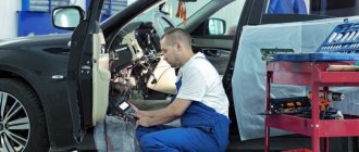
To increase safety (so that the driver does not start driving with the door open and for the alarm to work), cars are equipped with open door sensors (popularly “limit switches” or “limit switches”). Their malfunction causes the interior lighting to work incorrectly and prevents the car from being armed. Let's figure out how to check and, if necessary, replace door switches.
Wiring check
Instructions for cars of the B0 assembly line (XRAY, Largus, Nissan Almera, Renault Duster, Sandero). Remove the limit switch and set the multimeter to voltmeter mode. We measure the voltage at the contacts of the block with the wires:
- If there is no voltage, the circuit of the interior lamp lamp or the lamp itself is faulty.
- if the voltage is significantly less than 12 V, the wire connecting the sensor to ground is probably damaged.
We set the multimeter to ohmmeter mode, connect one probe to ground (body), and the other to the terminal of the block with the black wire. The resistance should be close to zero. If the resistance is high and tends to infinity, the connection between the wire and the body is probably damaged by corrosion or the wire is damaged (treat the connection with a product to protect electrical contacts). If the fault cannot be resolved in this way, it is necessary to remove the interior trim from the pillar, find and fix the fault.
FakeHeader
Comments 19
Hello, problem with vibration, did you solve it somehow or how?
I will also take a closer look at the advice. My handbrake light hasn't come on since I bought the car (it seems to have burned out)
The handbrake is paralleled with the brake level. close the contacts on the chip that is on the barrel plug. If it lights up, it means it's just the handbrake chain.
Closed - did not light up.
More likely + doesn't come. Or the light bulb on the panel has burned out or come off.
The light bulb is ok, I've already checked it.
Look along the path which terminal of the chip is coming and which is going out. Either + does not reach or minus does not go out.
Well, this is again drawing out the whole scale. Then sometime at your leisure.
The same principle is there. When the ignition is turned on, + comes to the light bulb. And the outgoing wire is divided into two: one goes to the handbrake limit switch and the second to the brake fluid level sensor. And from there to the masses. Since neither this nor that burns. It's somewhere out there. And you can see it visually there. Which contacts does the chip go to? If + comes and there is no access to ground through the handbrake and brake fluid reservoir. We look at the flail after the light bulb. If not + look at the circuit to the light bulb. And of course, don’t forget to ring the tracks on the board, you never know if there’s a crack.
Closed - did not light up.
+ comes to her? When the ignition is on?
It's pretty painstaking to check.
It was easier for me, the light bulb burned out.
I put the Vedashka tube under the rug and spray it. I massage it in the area of the button. and the grandmother whispered. enough for half a year
It didn’t help me. I just sprayed it with contact cleaner.
Yes, try another trick like checking the light bulb - with the ignition on, press the rubber knob of the cap on the brake fluid reservoir and ask someone to see if the light on the dash lights up. If it lights up, you will already know that you are not getting minus from the limit switch parking brake handles.
We're sorry, but the requests coming from your IP address appear to be automated. For this reason, we are forced to temporarily block access to the site.
To continue, please enter the characters from the image in the input field and click "Submit".
Cookies are disabled in your browser
. We will not be able to remember you and correctly identify you in the future. To enable cookies, follow the tips on this page.
Troubleshooting door switches
There are often cases when the door switch does not work.
There may be a lot of reasons for this, including dust, clogging and dirt, oxidation, or due to moisture getting inside during the cold season, it simply froze. The fault in this case lies only with the owner of the car, who, due to inattention, was unable to notice the non-working door switches in time. After all, monitoring their operation in each machine is very clear and it is difficult not to notice a non-working condition. But the solution to this problem today is quite simple - a sealed boot that completely covers the button and does not allow dust, dirt and moisture into this mechanism.
Before you start installing the boot, you need to pierce a cross-shaped notch on its underside where the end switch is attached. After this, you need to install a self-tapping screw in the button hole, then put on the boot and insert a screwdriver through the puncture and secure it to the body. This method surprises with its reliability, simplicity and accessibility.
Hood switch
What is a hood switch? This is still the same rod switch, except that the rod is longer than in the doors or trunk. Since the hood end is located on the front frame, the distance to the hood is quite large, which is why it is necessary to use a long rod.
This is the most rarely installed standard limit switch. On cars without a standard alarm system, it can be used by the factory only for the engine compartment lamp, which is offhand only remembered from the VAZ “eighth” family. Therefore, these alarm switches have to be connected independently, and therefore at least one limit switch is always included in the security systems.
But it also happens the other way around: for example, on Renault Megane 3 and Fluence for the Russian market it is standard in all trim levels except the minimum one, and is even built into the hood latch. And there are even wires going to it... but it’s impossible to find them in the cabin, because they remain under the hood, not connected anywhere. When installing an alarm, of course, you don’t have to install your limit switch, but you still have to run the wires under the hood.
This alarm switch will be the most problematic: water and dirt will get under the edge of the hood, causing corrosion, or failure of the switch, or false alarms. Therefore, you need to carefully select the location, if possible installing the limit switch in the cleanest available location.
Programming the standard control unit
Manufacturers, with each new car leaving the assembly line, increase its comfort and ergonomics. The cars are “stuffed” with electronic safety and comfort systems. They provide maximum driving pleasure.
The car central lock is a convenient and useful invention. Used over the past few decades. Its creation allowed the driver to get rid of unnecessary manipulations associated with opening and closing the driver's and passenger doors.
Since its inception, the central car lock has undergone a number of significant changes. Controls the opening of not only the doors, but also the trunk. The car's central locking cannot operate indefinitely. Sooner or later, malfunctions occur in its operation requiring repair or complete replacement of the system.
A person who gets used to good things is sensitive to the failure of comfort systems. He feels uncomfortable wasting time on manipulations that previously required just a finger press. A malfunction of the central locking forces the driver to look for information about why the central locking does not work.
At the end of the article you can find a video on how to repair a car's central locking system. It will be an excellent addition to the text material. Enjoy watching.
Door limit switch VAZ 2114: use, modernization and replacement
Limit switches - also known as limit switches - are electromechanical devices whose task is to open/close an electrical circuit. Although the device was originally developed for use in engineering structures, but with the increase in the number of electronics in vehicles, they began to be widely used in their control system.
So, since the 50s of the last century, almost all cars were equipped with an automatic system for turning on the light in the cabin when the front door was opened, but with the progress of progress, an increasing number of tasks began to be assigned to the limit switches used in the car, for example, the limit switches of the VAZ 2114 are located on the entrance doors and trunk.
Correct modernization of VAZ 2114 limit switches
The most common problem in cars of this series is that the driver's door switch of the VAZ 2114 wears out and then does not work, so there is no need to talk about the normal operation of sensors, alarms and even lights in the cabin.
The second most unpleasant problem that VAZ 2114 car owners may encounter is that the standard limit switches do not report that the door is not closed when it is slightly open by one click of the limit switch. Such a design flaw not only does not allow the car owner to be confident that all doors are closed, but also leaves a significant loophole for intruders.
Therefore, if you want the signal to be triggered even when the door is slightly open, you will have to slightly change its design with your own hands.
Modernization of the limit switch of the VAZ 2114
IMPORTANT! The design of the rear door limit switches on the VAZ 2114 differs from the design of the front doors; this should be taken into account when selecting materials and methods for solving the problem.
The essence of the problem is to reduce the stroke length of the limit switch to obtain the required response of the entire electrical network.
The simplest solution from available materials is the following modernization:
- We take the upholstery piston of your own car.
- We replace the standard “washer” with this piston.
- Using available means, measure the distance between the edge of the cap with the base; it should be 1 mm.
- We fix the design and check it; the light bulb in the cabin will act as a kind of quality control; it should light up after one click.
Although this method is not applicable for the rear door due to differences in design, it will help solve the problem of the front doors. Also, do not forget about fixing the piston; the ideal option would be a regular plumbing gasket of the appropriate size. On the back door, the limit switches will just have to be carefully ground off.
Replacing the limit switch with an alternative one
If a decision has been made not to sculpt the glue from scrap materials, then it is necessary to look for a worthy alternative. Let's say right away that the VAZ 2114 door limit switch can be easily replaced with a similar device with DAEWOO; we will need the General Motors device model 96235956 in the amount of 5 units.
We need to replace one limit switch with another, to do this we twist the old one and get to work:
- We start with the rear doors, where the analogs will become like family.
- We move on to the front door, where, due to the fact that our analogue is a little wider, the holes will not match, we will have to screw it in a little diagonally.
- Before doing this, it is necessary to solve the problem with the wiring running along the rack, due to the fact that our device is wider, it will not allow it to work normally. To solve this problem, a heat-shrinkable tube of the required size for the end cap is selected in advance; this will protect it from the cable.
- We assemble and check functionality.
IMPORTANT! If you couldn’t find the required tube, you can use scraps of cable duct or other dense material and fix them on the device, this is wrong, but it can help out for the first time.
Where do the door switches come from?
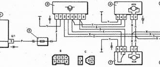
The general diagram of the VAZ 2114 door limit switches is shown in the diagram below:
In practice, it looks like this: a black and white wire goes to the limit switches, since they are responsible for opening the circuit, the white wire is responsible for the plus, and the black wire for the minus. So, for example, there are three wires going to the light bulb responsible for interior lighting: black and white, responsible for powering the light bulb itself, and black and white from the end switch.
As can be seen from the diagram, they are all connected in parallel, which means that the alarm system, the light bulb and the instrument panel are included in this network separately for each door.
Alarm connection
To install this device, the driver will have to become familiar with the concept of inserting wires.
Connecting an alarm system to limit switches
In order to carry out this simple operation, you do not have to disassemble the entire machine:
- Remove the sill trims and the side panel on the driver's door.
- We find there a wiring harness going to the dashboard (this is what is needed so as not to connect the alarm to each door in parallel).
- Having selected the white cable we need, we insert 1N5401 into it so that the direction of the current on the diode is directed towards the limit switches.
- We connect the 1N4001 paired with it according to the diagram shown in the picture.
- We find the handbrake wire; we need to embed 1N4001 into it so that the cathode is closer to the switch.
- We find a blue cable and solder a branch into it to the alarm unit.
- We turn on the alarm and test, and if something doesn’t work, first of all we “ring” all the solders, perhaps you soldered one of the diodes in the opposite direction.
In conclusion
Limit switches are a known problem in the VAZ line, but their repair, modification and maintenance can be done independently using the diagrams described above. It is better to entrust the installation of an alarm system to professionals, because the safety of the car is much more valuable than the saved “pennies”.
Source: https://vazremont.com/koncevik-dveri-vaz-2114
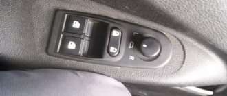
Connection points for standard alarm systems on Lada Priora
- Hood end (-) – white, black in the connector in the middle;
- Ignition (+) – orange in the connector in the middle;
- Button for opening the trunk lid (-) – black, white in a small connector;
- Luggage compartment end switch (-) – black, white in a small connector;
- Factory sound warning system - black, white on the safety panel. Owners of VAZ models change or improve the existing protection. Upgrading protection on a Priora is not difficult. To control the central locking, you need to cut the brown wire in the driver's door and connect according to the diagram.
Basic limit switches
- Ignition – blue, black, located in the ignition switch area;
- Starter – red;
- Turns – blue and blue with black line;
- Ignition – orange;
- The hood tip is white with a black stripe;
- The generator is black with a brown line.
How to tighten the handbrake on a Priora
Adjusting the handbrake on a Priora car is done in 7 simple steps, see them below. Normal operation of the handbrake lever is considered to be two to four clicks. Typically, an increase in clicks occurs every 20-30 thousand kilometers. The stroke of the lever must remain normal, so it must be tightened in time. It is not at all necessary to immediately buy a new set for Priora, because you can handle the tightening yourself.
Before tightening the cable, prepare the following tools:
- head "13";
- keys “13”, “10”;
- ratchet;
- technical lubricant.
Carry out the work according to the instructions:
- Place the car in a pit. If this is not possible, you can raise the rear of the car and then support it. It will be inconvenient, but this method will also work. Lower the handbrake lever and put the car in gear.
- Remove the metal cover under which the cable equalizer is hidden. Its tension is adjusted there. Remove the cover fastening bolts using keys.
- Coat the handbrake lever rod with lubricant to make adjusting the tension of the mechanical device easier.
- Loosen the stem locknut.
- Pay attention to the stem nut. If the handbrake needs to be tightened, reducing the number of clicks to normal operation, turn the nut clockwise. If you need to increase the number of clicks, turn the nut counterclockwise.
- Try tightening the handbrake. It should prevent the rear wheels from turning.
- Reinstall the metal cover.
Installation of limiters from Ford Focus 3
To work you will need the following tools:
- Collar;
- Torx bit T20;
- Torx bit T40;
- A plastic spatula for dismantling upholstery components - if you don’t have one, you can use a thin screwdriver, first placing a cloth under it so as not to damage the door card components and paintwork.
- Head for 10.
First you need to remove the door cards. First, use a plastic spatula to remove all components that block access to the bolts. You need to work carefully so as not to break the latches. Next, the mounting bolts are unscrewed using a T20 Torx bit. That's all - all that remains is to snap off the card, which is secured along the contour with caps
At the same time, it is important not to break the door opening handle, and also to disconnect the plugs for the electric windows. Then you need to remove the insulating material glued to the door to gain access inside
The next step is to dismantle the limiter itself. It is screwed to the body with one Torx T40 bolt, and to the door with a pair of bolts, to unscrew which you will need a 10mm socket. When the bolts are unscrewed, all that remains is to remove the limiter, but this must be done carefully, since you can lose the washers on the studs (in the places where the element is attached to door). In addition, after removing the limiter from the Vesta door, you need to make sure that the door does not open further than it should, which is especially important for the front doors. Otherwise, you can crush the edge and damage the paintwork.
The process of removing the upholstery and the door stop itself from the Lada Vesta is clearly demonstrated in the video
Installing limiters from Focus 3 in Vesta is not difficult, but there is one point. During installation, those 2 mm differences between the studs that were mentioned earlier begin to affect. For this reason, the limiter is not installed. There are two ways to solve the problem:
- Working with holes - you need to carefully drill out the seats with a drill or bore them with a file so that the element becomes as needed.
- Adjusting the studs - it involves bending the studs slightly inward so that they fit freely into the holes.
As practice shows, it is still better to squander the seats. Yes, it takes longer, but it is much more reliable. The reason is that the pins on the limiter are hardened, so if you bend them more than necessary, they can break and the limiter will have to be thrown away. In addition, before installation you need to put thick washers or nuts on the studs themselves. This is necessary, since the length of the element pins from Focus is several millimeters longer than those on Vesta.
If this is not done, the functionality of the component will not be affected, but at the end of the stroke it will no longer be a spare part from Ford that will stop the doors, but a factory additional stop. As a result, the paint will peel off very quickly and corrosion will appear at the contact point.
Once the stops are installed, you can reassemble the doors in reverse order.
Oil pressure sensor Lada Priora: where is it located, replacement - AutoExpert
First of all, don’t panic and run to the nearest service station. Indeed, when the light on the dashboard lights up, this may indicate a low oil level and a decrease in pressure, but there are times when the sensor does not operate correctly. It is best not to ignore the signal from this device, and if the light starts blinking, recheck the oil level, because if the device still made no mistake and you ignored it, this will lead to unnecessary troubles.
Where is it located and what does it consist of?
- Frame.
- Measuring membrane.
- Transmission mechanism.
Principle of operation
The level of deflection and location of the measuring membrane directly depends on the level of oil pressure in the system during a certain period.
Before checking the pressure sensor, you must make sure that the oil filter is working correctly and that the oil level is sufficient. The motor housing must be clean and without obvious signs of leakage. If all of the above is normal, then the cause is in the sensor itself.
We change DDT ourselves
First, remove the plastic cover from the motor. The DDT is located on the opposite side of the engine and is mounted on the right in the cylinder head hole. Next, disconnect the wire block from the DDM; to do this, press the block lock. Using an adjustable wrench, unscrew the DDT. The new sensor must be prepared for installation and mounted in the socket of the previous part. Finally, we clamp the contacts, install the plastic cover on the engine and check if the problem remains. If the light on the panel stops lighting, we can conclude that replacing this part was advisable.
The car starts to jerk at speed
For Soviet car models, getting the necessary part to replace it is not too difficult. For example, an oil pressure sensor for Priora can be purchased at your nearest auto store, and instructions for replacing it can be easily found on the Internet. If you do not dare to do this work yourself, then the nearest service station will do it for you in the shortest possible time and for little money.
As you know, the oil sensor in a car is used to determine the level of engine lubrication.
The importance of this small detail cannot be overestimated. Responsible motorists periodically check the oil level, as well as the engine and its surroundings for oil leaks.
However, a car is a technically complex organism, so there are many reasons why engines (especially old ones) can leak oil - leaking oil seals, oil filter, cylinder head gaskets, problems with the intake manifold, excessive amounts of oil filled, etc.
The car owner is often unable to track such a situation in time and the oil leaks out (sometimes at a decent speed). This is where the pressure sensor is triggered, causing the lamp on the instrument panel to indicate insufficient oil pressure (leakage).
In this case, the engine parts undergo increased friction against each other - as a result, the engine life is reduced. It is, of course, better not to let it come to this.
Cars often use two types of oil sensors - mechanical and electronic. If the first is connected to an arrow on the instrument panel, which shows the oil level, then the second turns on only when the amount of oil drops below the minimum (the so-called “emergency”).
Today we will consider replacing the emergency sensor on a Lada Priora car. The principle of its operation is simple - a curved membrane located inside such a sensor is pressure sensitive.
It is connected to electrical contacts, and these, in turn, are connected to a control lamp.
If the pressure drops below a certain value, the membrane straightens, allowing the contacts to touch, and the lamp lights up.
The oil pressure sensor, like another part, can break. If there is a suspicion that it is faulty (for example, the arrow indicator shows almost no oil or there is almost no oil on the oil dipstick, but the warning lamp does not light up), there are several ways to diagnose the sensor:
- Replace the sensor with a known-good device.
- Using a pressure gauge. It will need to be screwed into place of the sensor. If the pressure gauge reading is below 1 kgf/cm2, the sensor requires replacement.
- Unscrew the pressure sensor. Then you need to crank the starter, but do not start the engine. If oil flows out of the socket, it means the sensor is faulty.
Limit switch Lada Largus, door limit switch
Dear customers, in order to avoid errors when sending limit switch 7700427640, in the “Comment” line, indicate the model of your car, year of manufacture.
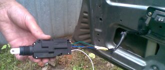
In simple terms, a door switch is a button, when pressed by a moving object, an action occurs that is entirely dependent on the actuator.
The door limit switch 7700427640 is designed to inform about the opening or closing of the Lada Largus door by closing or opening the contacts.
The operation of the limit switch 7700427640 for the Lada Largus is that when the doors are open, a special symbol lights up on the panel.
The car security system (system unit) is usually connected to the Lada Largus door limit switch. This design allows for maximum protection of the car door and trunk area. The limit switch is attached to the surface of the door and connected by electrical wires.
If, when setting the alarm, the door is not closed or not completely closed, that is, the limit switch is open, then the “alarm” will definitely notify you about this.
There are often cases when the door switch does not work. There may be a lot of reasons for this, including dust, clogging and dirt, oxidation, or due to moisture getting inside during the cold season, it simply froze. The fault in this case lies only with the owner of the car, who, due to inattention, was unable to notice the non-working door switches in time. After all, monitoring their operation in each machine is very clear and it is difficult not to notice a non-working condition.
The solution to this problem is a sealed boot that completely covers the button and prevents dust, dirt and moisture from entering this mechanism. Before you start installing the boot, you need to pierce a cross-shaped notch on its underside where the end switch is attached. After this, you need to install a self-tapping screw in the button hole, then put on the boot and insert a screwdriver through the puncture and secure it to the body. This method surprises with its reliability, simplicity and accessibility.
Other article numbers of the product and its analogues in catalogues: 7700427640.
PLADA Largus 4601, RENAULT Logan.
Any breakdown is not the end of the world, but a completely solvable problem!
How to replace the door switch on a Lada Largus car yourself.
With the AvtoAzbuka online store, repair costs will be minimal.
Just COMPARE and BE SURE!!!
Don't forget to share the information you find with your friends and acquaintances, because they may also need it - just click one of the social networking buttons located above.
The license plate light does not light up
Good afternoon, dear reader.
In this article we will talk about the fine for non-functional illumination of the state registration plate.
Light bulbs are provided only for the rear license plate of the vehicle. This is due to the fact that the rear license plate of the car must be readable even in the dark. There are no such requirements for the front number.
Let's consider what fine will be imposed on the driver if one license plate light bulb burns out or all the backlight bulbs burn out at the same time. Let's get started.
First of all, I would like to note that driving a car with non-working external lighting devices is prohibited by paragraph 3.3 of the list of faults:
3. External lighting devices
3.3. External lighting devices and reflectors do not work in the prescribed mode or are dirty.
Light bulbs for illuminating state registration plates are classified as external lighting devices. Therefore, operating a car whose light bulb does not work is a violation of traffic rules. We are also talking about a situation where there are several light bulbs in the rear license plate, and only one of them does not work.
Fine for lack of rear license plate illumination
The lack of illumination of the rear registration plate makes it unreadable at night:
1. Driving a vehicle with unreadable, non-standard or installed in violation of the requirements of the state standard state registration plates, except for the cases provided for in part 2 of this article, -
entails a warning or the imposition of an administrative fine in the amount of five hundred rubles.
Note. A state registration plate is recognized as non-standard if it does not meet the requirements established in accordance with the legislation on technical regulation, and unreadable if at a distance of 20 meters it is not possible to read at least one of the letters or numbers of the rear state registration plate at night, and in daylight hours of at least one of the letters or numbers of the front or rear state registration plate.
This fine can only be imposed at night if, due to the absence of a light bulb(s), the number has become unreadable.
For example, if one of two bulbs has burned out and the first letter of the number is not visible from 20 meters away, then the number is unreadable and the driver will receive a warning or a fine of 500 rubles.
Another example. If one of the two bulbs has burned out, but the remaining bulb illuminates the number well and all its symbols are visible from 20 meters, then this fine cannot be imposed.
Fine for faulty license plate light bulb
Let me remind you once again that the rear license plate illumination is an external lighting device. Operating a vehicle with such a malfunction is prohibited. In addition, for this violation there is a fine under Article 12.5 of the Code of Administrative Offenses:
1. Driving a vehicle in the presence of malfunctions or conditions under which, in accordance with the Basic Provisions for the admission of vehicles to operation and the duties of officials to ensure road safety, operation of the vehicle is prohibited, with the exception of malfunctions and conditions specified in parts 2 - 7 of this article, -
entails a warning or the imposition of an administrative fine in the amount of five hundred rubles.
Thus, a driver may receive a warning or a fine of 500 rubles for a non-working light bulb. Moreover, this fine, unlike the one discussed above, will be imposed even if the number remains readable after the backlight fails.
In 2022, the fine for non-working rear license plate lights is not very large - a maximum of 500 rubles. Nevertheless, it is very unpleasant to receive it, especially since the price of a new light bulb is much less.
Repair of electric central locking
Electric central locks on cars are sensitive to temperature changes and high air humidity. At first they start to freeze and after a short time they refuse to work.
Causes of malfunction of the electrical central locking system:
1.Breakage of electrical circuit wires.
Careless actions when dismantling doors or repairing them lead to a break in the electrical wire in the corrugations. It is necessary to “ring” the electrical circuit to find damage
2. Relay failure.
The damaged relay is replaced and the system operates as before.
3. Malfunctions of the control board.
It is being repaired or replaced.
4. Wear of motor gears.
Active use of the central locking system leads to wear and tear on the working elements of the motor. Plastic gears suffer. They wear out as a result of work. They are being replaced.
The central locking system in a car is a useful and convenient feature for the driver. To repair it, you need to understand the structure and principle of operation.
Thank you for your attention, good luck on your journey. Read, comment and ask questions
Subscribe to fresh and interesting articles on the site.
Replacing the handbrake and front parking brake cable on a VAZ 2101-VAZ 2107
Welcome! There are two cables in total in the car, namely the rear and front handbrake cables. The front one, coming from the parking brake and having a short length. It goes to the rear, compared to the front cable it is very long. The rear one goes directly to the two rear wheels. Thanks to the cable system, the car is braked.
Note! You will have to remove the handbrake, which means the following tools will be useful: various kinds of wrenches, a screwdriver and pliers.
Part location
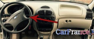
It comes from the handbrake and passes under the bottom of the car, connecting to the rear (main) cable. Below we have attached a photo with a diagram of the handbrake. The front cable is indicated by number 2.
Note! In the diagram above it may seem that cable number two is divided into two parts, but in fact it is not. It is solid, just in the place where it supposedly breaks (in the diagram) there is a roller (indicated by number 8).
When to change the cable and the handbrake itself?
You have to change it when the cable breaks. You will feel this when the handbrake begins to rise very easily and to a very high position, almost to a vertical position. Exactly the same situation will arise if the cable breaks at the back. Therefore, before you go to a car store and buy a new one, inspect the bottom of the car and figure out which cable has become unusable.
Note! The cable tends to stretch over time. It all depends on the quality of the material; a high-quality cable will last longer and stretch to a shorter length. If you see that this cable is sagging and the adjustment does not lead to anything good, then you will have to replace it with a new one!
Now let's talk about when to change the handbrake itself. Firstly, there is a gear sector on the parking brake, thanks to which the handbrake rises up neatly and does not slip between clicks. Secondly, the so-called pawl, which blocks the handbrake after lifting up, its breakdown leads to the handbrake not being held in one position, it will constantly fall. These factors are a reason to replace the part with a new one.
Removal
Remove the guide from the tip of our cable, for more details see the article: “Replacing the rear cable”, points 3-4.
Take a wrench and remove the bolt securing the roller to the bracket (the bracket is indicated by the blue arrow). Carefully remove the roller by rolling the roller towards the tip of the front cable, as shown in the figure, and remove it from the car.
Note! Be careful: inside the roller there is a bushing (number 3 in the photo below) and a fastening bolt (number 1). Don't let the parts fall and get lost.
We recommend using Litol-24 or LSC-15 lubricant, lubricating the contacting surfaces of the bushing itself (the surface is indicated by the letter B) and the surface of the roller (the letter A). To do this, remove the bushing from the socket.
Now pull the cable to the bottom and remove the cable from the bracket and the intermediate support of the cardan drive (indicated by the blue arrow).
Get out from under the bottom of the car and move into the interior. While inside the car, remove the two screws securing the handbrake trim, remove it and set it aside.
You will see four handbrake mounting bolts. By unscrewing them, you will remove the handbrake from the car along with the attached cable (front).
Note! If necessary, disconnect the cable from the handbrake: using pliers, remove the small cotter pin (looks like a small twisted wire inserted into the hole; a washer is placed under it, holding the parts in place) that goes into the hole indicated by the red arrow. Unfortunately, the hole is hard to see in the photo, but it is present in the so-called finger, where the cable tip is installed. Remove the cotter pin securing the end of the cable and remove the washer with the cable as shown in the figure below.
Installation
New parts are installed in the reverse order of removal. ,After installation, adjust the cable; the process is described in detail in the article: “Adjusting the cable.”
Note! Is the handbrake button stuck? Most likely the spring is to blame. It can be easily removed and replaced with a new one:
- Unscrew the handbrake button completely;
- pull out the hole button together with the spring;
- replace the spring with a new one;
- Reinstall the parts in reverse order.
Source: https://vaz-russia.com/remont/zamena-ruchnika-i-perednego-trosa-ruchnika-na-vaz-2101-2107.html
Checking the door switch
When the rod is recessed, the contacts are open. First of all, we check the serviceability of the sensors by opening all the car doors one by one.
Check with a multimeter. We connect a multimeter to the limit switch terminals in ohmmeter mode and check the closure of the sensor contacts (the contacts must be closed, the resistance is close to zero). We press the sensor rod and check the measurements (the contacts must be open - the resistance tends to infinity).
Let us remind you that in some cases (for example, in the cold season) limit switches may work intermittently. For Lada Vesta, Grant and Kalina 2 you can use this solution, and for Priora this.
Replacement
To remove the limit switches, open the doors, then:
- remove the protective cover from the sensor by simply pulling it towards you.
- pry off the limit switch with a screwdriver
- remove the limit switches by snapping off the three latches
- disconnect the block with wires.
On some Lada models (for example, Lada Priora or Niva 4x4), the limit switches are attached to the body with a screw.
On the Lada XRAY the limit switch is located in the door lock and changes along with the lock.
Installation is carried out in reverse order.
Door switches on Lada Granta Liftback
Structurally, each limit switch is located in the lower right corner of the doorway. As soon as the door opens, the contacts open and a signal is transmitted to the dashboard and interior lighting unit.
Freezing of the rubber tip contributes to the hardening of the cap and unstable operation of the door activation mechanism. To maximize the service life of rubber tips, they are periodically lubricated with silicone grease to maintain (increase) elasticity. Fixation to the body is carried out using spacer clamps made of plastic. When the base is inserted into the socket, the clamps expand, preventing the base from moving freely.
To connect the sensor to the power circuit, two terminals “+” and “-” are connected to the wires coming from the interior lighting. Be sure to observe polarity! As a rule, “plus” is indicated by red insulation, and “minus” by white with a black stripe.
Description of the brake pedal sensor
Below we will find out how it works and how to replace it.
Purpose, location and operating principle
The essence of the system is that when you press on the brake, the piston in the cylinder begins to move. After this manipulation, fluid enters the brake system from the intake valve. It passes through the pipelines towards the main wheel mechanism, thus creating a suitable situation for the pads to move towards the wheel discs and drums. As a result, contact and subsequent braking occur. The controller itself turns on the brake lights.
Typical malfunctions and methods for their elimination
When “communicating” with a car, you can encounter various problems, but there is the most common and annoying problem. This problem is called error P0504, or otherwise “Brake pedal sensor mismatch.”
This malfunction often slows down the car. To solve this issue, you need to release the brake pedal and adjust the gap in the position sensor.
Functions and purpose of the central lock
The car's central locking is the “heart” of the security system. Responsible for monitoring the locks in the car. That is why it is called central. The signal sent from the key fob symbolizing the central control unit closes or opens the doors, windows, trunk and hatch.
Central locking is one of the car's auxiliary comfort systems. The development of the central locking system does not stand still. New car models are equipped with a system that ensures automatic closing of door locks when driving. Some car models combine central locking and alarm systems under a single control.
Description of the clutch pedal sensor
What kind of device is this and how to replace it is below.
Purpose, location and operating principle
The clutch sensor is installed directly on the clutch pedal. It influences engine control with an electronic gas pedal and provides a convenient and flexible control scheme for machine modes. On its own, it looks like a nondescript switch that has on and off modes.
Typical malfunctions and methods for their elimination
Reliability level
Undoubtedly, the standard alarm system installed and configured on the Lada Priora is simple, reliable and fully adapted to difficult local weather conditions. Properly activated, it leaves no doubt about its functionality. Besides:
- the quality of installation and configuration of factory alarms is guaranteed by experienced factory specialists and the control service of the enterprise;
- The key fob is integrated into the regular ignition key. There is no need to wear them separately in a whole bunch;
- there is no need to equip standardly installed equipment with anything;
- The factory alarm system of the Lada Priora is covered by the factory warranty;
- if the Lada owner wishes to install and configure an additional sensor, there is a spare port;
Why did it happen so?
Perhaps the automatic requests do not belong to you, but to another user accessing the network from the same IP address as you. You need to enter the characters into the form once, after which we will remember you and be able to distinguish you from other users exiting from this IP. In this case, the page with the captcha will not bother you for quite a long time.
You may have add-ons installed in your browser that can make automatic search requests. In this case, we recommend that you disable them.
It is also possible that your computer is infected with a virus program that is using it to collect information. Maybe you should check your system for viruses.
If you have any problems or would like our support team, please use the feedback form.
Source: o-ladagranta.ru
If the central locking from the key fob does not work: troubleshooting sequence
p, blockquote 24,1,0,0,0 —>
Any repair or troubleshooting in a car must begin with checking the fuses that serve a specific system. There are three of them in the diagram below. Usually it can be more. You need to find their location using the car's instruction manual or searching on the Internet.
p, blockquote 25,0,0,0,0 —>
Video - if the central locking does not work from the alarm, then first check the fuses:
p, blockquote 26,0,0,0,0 —>
p, blockquote 27,0,0,0,0 —>
If all fuses are in good working order, proceed to determining the location of the malfunction based on its characteristic symptoms.
p, blockquote 28,0,0,0,0 —>
Central locking does not close the doors
There are several options for central locking:
p, blockquote 29,0,0,0,0 —>
does not respond to the key fob signal at all, in this case it is necessary to check, or better yet, immediately change the key fob battery;
does not close the door even with the lock key;
closes and immediately opens the doors.
The last option is associated with loose closure of windows or doors. It is necessary to try to press each door sequentially, supporting it with your whole body, and at the moment of pressing, try to close the central locking.
p, blockquote 30,0,0,0,0 —>
Perhaps a foreign object has gotten into the closing area of a door; it needs to be checked. You should also check the pressure of the glass so that it fits tightly into the upper grooves.
p, blockquote 31,0,0,0,0 —>
If the central lock does not respond to the key fob and key, the wires may have broken in the area of the corrugation entering the door. If you have experience repairing electrical wiring, you can find the faulty wire and connect it.
p, blockquote 32,0,0,0,0 —>
The central locking system does not open the doors, but at the same time closes them
One option is to shift the door hanger. The lock is locked with a door latch. This type of malfunction often occurs in the trunk doors. You have to press them manually to wedge the movement of the lock drive. When you try to open the door, you should hear a click from the drive. In some cars it is almost inaudible; you have to put your ear to the door.
p, blockquote 33,0,0,0,0 —>
Central locking only closes the driver's door
Here, most likely, the malfunction is a breakdown in communication from the driver's door control unit to the central unit or other doors. You should remove the corrugated hose from the wiring transition from the driver's door to the car interior - there will be a break there.
p, blockquote 34,0,0,0,0 —> adsp-pro-2 —>
In some car models, there is a connecting connector at the junction of the wiring into the car interior; you can check its contacts. It is also necessary to examine the electrical wiring under the door trim and all connectors.
p, blockquote 35,0,0,0,0 —>
One of the doors does not open
Possible malfunctions: damage to the electrical wiring in the corrugation or on the way to it in the cabin, malfunction of the lock drive.
p, blockquote 36,0,0,1,0 —>
Video - the central locking of the driver's door on a Skoda Fabia does not work:
p, blockquote 37,0,0,0,0 —>
p, blockquote 38,0,0,0,0 —>
The lock drive is easy to replace and is inexpensive. During replacement, the main thing is not to damage the levers, rods and plastic tips.
p, blockquote 39,0,0,0,0 —>
p, blockquote 40,0,0,0,0 —>
If you replace the central locking drive yourself, to be sure, it is better to find a mechanical diagram on the Internet, reference books, or instruction manual so that you do not forget to install any part.
p, blockquote 41,0,0,0,0 —>
p, blockquote 42,0,0,0,0 —>
Why does the central locking system not work?
Quite often a situation arises when the central lock cannot be opened with a key or key fob.
As a rule, the problem here is solely due to a faulty relay or due to damaged wiring. If the key normally opens the central locking system, but the key fob does not, then most likely the battery in the latter is simply dead or its button needs to be cleaned. Experienced specialists note that in their practice, signal receiver or transmitter failures have occurred extremely rarely. You can check it simply - just use a spare remote control or insert a new power supply into the existing one.
The inability to open with the key is due to incorrect operation of the activator. This device is located directly in the driver's door, and it is responsible for distributing the signal through the locking mechanism. First of all, in this case, check:
- wiring;
- circuit breakers;
- terminals.
To inspect the activator, you will need to remove the trim from the previously mentioned door.
Finalization of the scheme
Work on modifying the door end elements can be delegated to service station specialists. In this case, the owner will be charged an installation fee. You can do everything yourself, then installing limit switches will require plumbing tools and a device for checking the electrical circuit:
- Tester.
- Soldering iron.
- Phillips screwdriver.
- The wire.
- Solder POS-40.
- Corrugated hose.
- Insulating tape.
- Limit switch.
Both options involve parallel connection of unused elements to the working terminals of the door on the driver's side. The switches for opening the doorway of a Lada car are powered using a two-wire circuit. To simplify the choice, we will consider both options.
Why is everything so difficult?
It would seem that we only need to manage the locks. Why then connect to the window lift motors?
The opening of the passenger doors is carried out by the second impulse (relay K1 is activated). And elements K2 and K3 at this moment block the power windows. If they are not blocked, the windows in the doors will lower during the entire control pulse. And even in 0.8 seconds they will open noticeably.
Of course, connecting the signaling system in a Priora is more difficult than in many domestic cars. At the same time, the “Grant” in the “Norma” configuration uses a similar scheme. Be that as it may, the Lada Priora is the flagship of VAZ. And probably, difficulties with the electrical part should not confuse a competent car owner. It is also known that the standard control unit can be reprogrammed, and then unlocking occurs in one step. In this case, the connection is made according to “Scheme 1”.
Method for finding door limit switches for connecting car alarms
To search for circuits, try to use a voltmeter (especially in cars of recent years of production), since using a lamp probe may damage the car's auto electrics!!!
Limit switches are usually of 2 types. Positive (when the doors are opened, +12 Volts hang on them) and negative (when the doors are opened, they are shorted to ground). Positive limit switches are much less common (domestic GAZ-Volgas, bourgeois Fords, some BMWs, sometimes standard trunk limit switches of various cars) than negative ones. Some alarms do not even have a wire to connect the positive end switch.
So, we take a probe, sit on the “plus” with one end, and start poking at the wires with the other. If the probe light lights up, then press the door button or click the lock on the door, looking at where the limit switch is (all remaining doors must be closed) - if the light goes out, then it’s the negative limit switch. Now do the same with the other doors without changing the position of the probe. If the probe light in this case behaves the same way as with the first door, then you are lucky: all the door limit switches are tied, and you don’t have to worry anymore about finding the remaining limit switches.
It happens that the limit switch for each door runs on a separate wire. Then you have to look for every wire. In this case, the method of searching for limit switches is no different from the above. You just have to cut into these wires, drag the cut ends to one point (to the alarm) and there, using diodes, connect to the alarm wire (negative door trigger). We install the diodes so that the negatives from the door buttons go to the alarm wire, but do not go to the other buttons. Read more about the use of diodes in the article Diode and its use when installing car alarms.
It can be easier and more convenient to cut into the wire going to the interior lighting lamp. In this case, you need to look: the light goes out immediately after closing the doors or after a few seconds. If immediately, then you can safely cling to this wire. If not, then you need to program the alarm so that it will arm the doors not immediately after arming, but after some time (each alarm has its own values for this interval).
When installing a car alarm with auto start, pay attention - when starting and stopping the engine, the light in the cabin should not light up; if it does light up, then you cannot cling to such a light bulb (the alarm will assume that the doors have opened and the siren will turn on). When searching for positive limit switches, we sit down on ground with one end of the probe, and start piercing the wires with the other
The technique is the same as described above
When searching for positive limit switches, we sit down on ground with one end of the probe, and start piercing the wires with the other. The technique is the same as described above.
At the end of this section I will tell you where it is better to look for the limit switch wires. The wires to the interior lighting lamp are most often located in the driver's or passenger's side pillar. You can ring the wires in the passenger and driver thresholds. You can very easily find the limit switch behind the instrument panel. You’ll be lucky if there are inscriptions for the tracks behind the panel (doors, for example, on a Nissan, this is DOOR) or you can easily trace the path from the light bulb where the open door is drawn to the connector where the wire from the door buttons goes. It happens that there is not a light bulb on the panel, but a diode. In this case, it can be said 100 percent that the limit switches are untied and each one will have to be looked for separately
Usually, the negatives from each button come to one point - the fuse box, radio-controlled central locking unit, original alarm system, etc. — then one common wire goes to the instrument panel, but on this wire there is already a different signal, and not 12 Volts. The most difficult way is to run wires into each door (for example, in Volkswagen they had to do this, since in each door there was a block into which the negative signals from the door locks entered, and modified signals went from the block into the cabin). It was not possible to connect to the interior lamp for the reason I mentioned above.
There are even more difficult cases when using a probe it is not possible to find limit switches. For example, Fords are the latest. When the doors are open, +12 Volts hang on the end wires from the doors, but these wires can only be found with a voltmeter. It also happens that the wires from the door limit switches have to be connected through resistors (resistance). Well, these are complex cases and, as a rule, the owners themselves do not install alarms on such cars.
Lada Priora, problems with central locking and driver's limit switch.
The problem is with the central locking, I go to the car and disarm it, open the driver’s door and sit down, I don’t close the door and don’t insert the key, and then the central locking starts numerous times closing and opening, followed by arming, and I’m sitting and my door is open.
It turns out that the locks of all doors open and close numerous times only when the driver’s door is open, but pay attention, this does not always happen, but happens “once-every-once” or “once-every-twice” or “twice-every other time”. I also managed to open the driver’s door with the key without the siren going off, the car was on guard, then I opened the rear passenger door, the siren went off. The conclusion is that for some reason the signal from the driver's door switch is jammed, but the light in the cabin comes on and the radio regularly sees the open door.
The car is new, Priora 2, 4000 mileage. Even during my tests, I armed and disarmed it many times, I managed to disarm it once, but the central locking did not work, that is, the doors did not open and the security was turned off.
Alarm connection points for VAZ 2114.
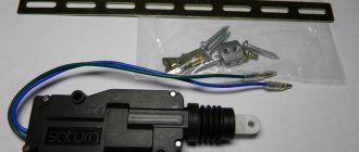
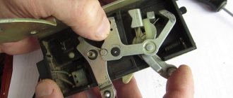
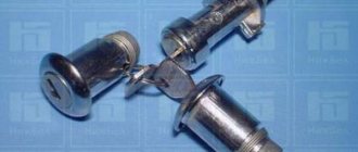
| The drawings and photographs show the main types of limit switches used for car alarms. The main problems arising with limit switches: The first is incorrect adjustment. In one case, the limit switch may break if the setting is unreasonably high. In another case, the limit switch stroke is very small. The hood or trunk lid may have natural temperature deformations, which can result in false alarms. If the limit switch stroke is small, moisture and dirt may enter the gap between the contacts, which can also cause false alarms. The second problem is the incorrectly chosen location for installing the limit switches. Sometimes they choose a place where the limit switch is easy to break, next to the standard battery (in case of careless battery replacement). In drains or places very close to them. In places where there is insufficient travel at the bottom of the limit switch. The third problem with limit switches is the rapid oxidation and corrosion of contacts. As a rule, a plus is supplied to the limit switch contact through the filament of the interior light bulb; other electronic units or alarms tend to pull the input to the positive potential to avoid false alarms. In this case, moisture (condensation) gets on the contacts and a slight leakage of electric current occurs. This is not enough to light the interior lamp or set off the alarm, but it is enough for the electrochemical reaction of oxidation-decomposition of the metal. After some time, this limit switch stops working. A slightly different situation occurs if the limit switches directly turn on the interior lamp. Small sparks at the moment the limit switch closes form carbon deposits and for this reason the interior lamp may not turn on, which means that when this door is opened, the alarm will not work. |
| Our domestic auto industry especially suffers from this, and more specifically, the door switches of VAZ cars. Usually they are cleaned with a file or sandpaper, but this usually lasts for no more than a month. It is better to replace these limit switches with new ones. The ideal case would be to use a reed switch-magnet pair. In this case, the contacts to be closed are reliably insulated in the glass bulb of the reed switch. Unfortunately, the majority of reed switches open when the magnet is removed. Although you can find locking reed switches, it is necessary that they work reliably on metal surfaces of the body, since there are special reed switch-magnet pairs for metal surfaces. Below are several more types of limit switches. The most durable in photo-2, on the contrary, the most quickly oxidized in photo-1 and photo-4. |
| Two diagrams for connecting a car alarm to the door and hood-trunk limit switches. |
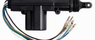
Most likely, you will need to install a 5-wire activator in the driver's door. The wires in the door are already there from the factory. Connect the activator to the red and yellow wires in the door. If there are no wires in the door, you will have to pull the yellow and red wires into the cabin to the central locking unit. The block is located on the left above the clutch pedal. Limit switch activator, connect to the end of the standard door lock. Black - mass, blue/brown - open/close.
The problem of how to connect an alarm system to the central locking of a domestic car has been relevant for VAZ owners since 2000. Before this, central locks were not installed at all on Tolyatti models. Now the useful device is offered for basic configurations as an additional option. Realizing the benefits of central locking and car security alarms, many car owners install both devices on domestic cars of all years, especially since self-installation helps save money. VAZ models make up about half of the country's car fleet, and ensuring their safety is of interest to millions of drivers.
Door switches: where they are located, connection, checking
Initially, limit switches were installed on the doors to automatically turn on the interior lamp. Their connection scheme was the simplest - everything was connected in parallel, that is, it did not matter which door was open. In budget car configurations, only the driver's door switch was often installed.
Video: Problems with limit switches in Lada Vesta, Grant and Kalina
The weak link of such limit switches was the need to place them in an extremely inconvenient place: the protruding part of the metal sheet of the door in the lower corner pressed on them; less often, designers managed to place the limit switch higher. Because of this, they often failed even despite the sealing cap on the outside. For a car with an alarm, this meant randomly triggering the alarm at the wrong time, or, just as bad, being able to open the door without setting off the alarm.
Subsequently, the connection diagrams for limit switches in doors became more complex - initially to indicate a specific open door on primitive on-board computers. Here, each door had its own signal wire, which complicated the installation of alarms: since the limit switches need to be connected to the only input of the central unit, an attempt to connect it with all the limit switches immediately leads to a violation of the display on the on-board computer screen (shows all doors open at the same time). Because of this, it is necessary to use diode isolation, which allows you to logically combine the outputs of the limit switches without disturbing the operation of the computer.
It works simply: since the diode conducts current only in one direction, when any of the limit switches is closed, the alarm output is connected to ground in any case, but the pressed one is connected to the rest of the limit switch wires through a back-to-back pair of diodes that do not pass current.
The solution to the problem with the reliability of limit switches turned out to be quite simple. It has long become the norm that the door end is located in the lock mechanism itself, that is, it is raised high and well protected from water, if, of course, the glass seal is in good working order. Note that the very principle of operation of the door limit switch has changed. If the door limit switch is installed in the slam, then it is triggered at a certain position of the door, closing the contacts when it begins to open.
If the door switch is in the lock, it is triggered by moving the locking mechanism: often (but not necessarily) it is enough to lift the handle without opening the door itself to close the contacts. This, by the way, makes installing alarms more convenient: you can leave the door open during operation by clicking the lock pawl with a screwdriver, and the alarm will no longer “see” the door open.
It is so good, for example, to adjust the shock sensor by arming the car with the door open, and not repeating the cycle “closed - armed - struck - disarmed - opened the door - changed the setting” for each adjustment.
On modern cars, the driver's door switch has received one more function - it is usually responsible for “falling asleep” and “waking up” of the on-board electronics. For this reason, on alarm systems with auto-start, it is necessary to connect a circuit simulating the opening of the driver’s door: the on-board controller at the end of the auto-start cycle will “see” that after turning off the ignition the door opened and closed, and will normally switch the car into a low-power mode.
In this case, a short-term “ground” pulse often appears on the limit switch wire, which, with a conventional diode isolation circuit, triggers an alarm for opening the door some time after arming. To avoid this, the diode decoupling circuit is complicated.
The difference with the previous diagram is that the diodes also cut into the standard wiring, and the alarm is connected between the diode and the limit switch. In this case, when the limit switch is closed, ground comes to both the standard vehicle on-board circuit control unit and the alarm system. But, when the controller creates a “ground” pulse in the standard wiring, the alarm input is blocked by back-to-back diodes, and no alarm is triggered.
It is important to understand that the duration of such pulses is very short, and the alarm can work correctly even when decoupled with one diode per line: for example, Sherkhans are less sensitive than StarLine, according to the author’s experience. But sometimes random operations are possible, and this is often associated with owner problems, when the limit switches are absolutely in good working order, but the car still sometimes “screams on its own.”