Print this article Font size 16
In our material today we will talk about how the ignition module on a VAZ 2114 is checked, how it works and why so much in the car depends on its functional state.
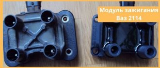
Ignition module
PRINCIPLE OF OPERATION OF THE MODULES
The VAZ ignition module is an improved engine starting system. The principle of its operation is not very different from conventional systems. If in older systems the high-voltage voltage was generated by opening the contacts in the ignition distributor, then in the module the signals from the control unit serve as a pulse generator.
The control unit collects signals from sensors on the engine, generates a control pulse and sends it to the ignition module of the VAZ 2115. In it, a high-voltage voltage is generated from the on-board network voltage and sent to the cylinder spark plug to ignite the air-fuel mixture.
Crankshaft position sensor (CPS)
DPKV is installed near the timing belt, namely near the crankshaft gear. This sensor is responsible for counting the crankshaft revolutions from the generator belt pulley. DPKV is involved in the formation of the spark necessary to ignite the fuel mixture in the combustion chamber. If the crankshaft position sensor fails, the car engine will not start.
Signs of DPKV malfunction:
- The car's internal combustion engine does not start;
- Spontaneous stop of the internal combustion engine;
- Uneven operation at idle and high speeds;
MODULE DEVICE
Design (circuit) of the VAZ 2114 ignition module
The device includes two coils, the main task of which is to generate high voltage. A two-channel electronic switch helps them in this. All these parts are contained in a housing made of durable plastic. The housing has a low-voltage connector for connecting the supply voltage and supplying control pulses. There are also leads for connecting high-voltage wires that are connected to the spark plugs.
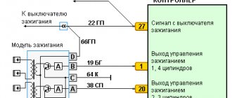
Electrical diagram of the VAZ 2114 starting system
The figure shows an electrical diagram of the VAZ 2114 starting system. As can be seen from the figure, it consists of:
- Battery;
- Ignition switch;
- Relay that turns on the ignition;
- Hall Sensor;
- Semiconductor signal receiver from the sensor;
- Electronic switch;
- Ignition module.
- High voltage terminals.
The electrical diagram also shows the fuses of the power supply circuits of the electronic units. Let's try to look at the device and operating principle of the ignition coil. As already noted, there are two of them in the block; they are identical in design. The ignition coil circuits of one and the other are also absolutely identical. The principle of operation of the ignition coil remains the same. Both consist of cores made of electrical steel. Two windings are wound on them. One of them is low-voltage, and the second produces high-voltage voltage to ignite the working mixture.
The ignition coil connection circuit is made in such a way that one end of the low-voltage winding is connected to the supply voltage, and the other end of these windings is connected to a transistor generator. Each coil has its own transistor. The high-voltage leads are connected directly to the spark plugs; each winding supplies energy to two spark plugs. One of them outputs pulses to cylinders 1 and 4, and the second to cylinders 2 and 3.
The wires on the ignition module are arranged as follows. Contacts A and B receive control pulses from the electronic switch, pin D receives power from the machine’s on-board network. The terminal marked with the letter C is connected to the vehicle ground.
Video: VAZ 2114 sensors - what they are and what they do
Signaling devices called sensors are installed in order to inform the driver or some control device about changes occurring during the operation of the car or about the state of the corresponding unit or system, as well as to signal in case of failures or emergency conditions in the car. Therefore, the driver must have a good understanding of the operating principle and location of the sensors on the VAZ 2114.
- The oil level has dropped significantly;
- the oil filter is clogged;
- the oil pump has failed;
- oil pressure sensor is faulty;
- The wiring is faulty or the oil pressure has dropped due to leaks.
On an eight-valve engine, the sensor is located on the right side below the valve cover in the cylinder head. On a sixteen-valve engine - on the left end of the camshaft bearing housing.
Where is the coolant temperature sensor located on the VAZ 2114
For proper operation, ensuring the collection and transmission of optimally accurate indicators, the DTOZH must be located in direct contact with the measured medium, that is, it must be immersed in the coolant.
Let's look at a temperature sensor using the example of one of the cars in the Lada model range.
The cooling system of VAZ cars is a complex of the following parts:
- heating and cooling radiators;
- fan;
- pump;
- expansion tank;
- coolant temperature sensor.
The measuring device, located between the thermostat and the cylinder head, consists of a resistor and is connected to the control unit by two wires.
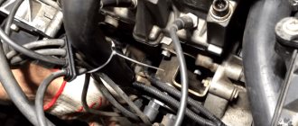
WHERE TO FIND THIS MODULE
It is hard to believe that the driver who undertakes to check or repair this device does not know where it is located. Well, for those who don’t know, we’ll tell you. It’s easy to find it, find at least one high voltage wire, and walk your hand along it from the spark plug to the plastic case that belongs to the module.
From the picture its location becomes clearer.
Phase sensor (PF)
The phase sensor is located:
- In 16-valve engines near the intake camshaft gear;
- In 8-valve engines from the end of the cylinder head near the mass air flow sensor;
Serves for phased fuel injection. It is a fairly reliable sensor that rarely fails. The design of the sensors for 8 and 16 valve engines is different and is not interchangeable.
Signs of DF malfunction:
- Increased fuel consumption;
- Engine vibrations;
WHAT ARE THE FOLLOWING SIGNS OF MALFUNCTIONS?
When asked what are the signs of a malfunction in the VAZ 2114 ignition module, any driver will say without hesitation that there is no spark at the spark plugs. This is partly true, but there are several other possible reasons for the failure of this device. You can see the following:
- The dynamics disappeared during acceleration, dips in engine performance appeared when the gas pedal was sharply pressed to gain speed;
- A decrease in engine power has become noticeable; drivers say in such cases that the engine does not “pull”;
- The idle speed floats a lot;
- There is no spark on one of the pairs of spark plugs.
When signs of a faulty ignition coil appear, the test should begin with the spark plugs, which do not work, then the sensor indicating the position of the crankshaft is the last module to be checked.
conclusions
As a rule, the ignition module is not restored and is simply replaced with a new one. There is no guarantee that he won't start bucking again. This will save a lot of gray brain cells and save a lot of personal time, which can be spent on something more necessary. It's better to buy a new one and not worry.
However, as children, we all loved to take toys apart to find out what was inside and how everything worked. It’s not a pity to try to disassemble a broken unit, but still throw it away if nothing works. But if you repair it, you will get so much pleasure and pride in yourself!
HOW TO CHECK THE SYSTEM FOR OPERATION
In any case, the check begins with the candles. To do this, they need to be removed from their nests. This is also easy to do. Remove the tips of the high-voltage wires from them and, using a wrench for turning out the spark plugs, remove them from their places.
Next comes their inspection, cleaning and testing. They should have a working brown color, with no soot or soot. If their presence is observed, then there may be wear on the pistons and rings. In any case, the spark plugs are cleaned, checked and, if necessary, the gap between the electrodes is adjusted. After this you can check their functionality
There are special probes for these purposes. “Craftsmen” manage to make such products themselves from a piezo lighter. If nothing like this is available, then check it on the engine. It’s good if there is a car nearby with a known good starting system. This will make it possible to make an accurate diagnosis for candles. If they are in good condition, the search continues further.
Many publications recommend checking for the presence of high voltage voltage at the terminals of the device. Doing this in a garage is problematic due to the lack of a special measuring device. A conventional tester is used here, since it cannot measure several tens of kilovolts of high voltage. If you have experience as a radio amateur, you can assemble a voltage divider.
Checking for the presence of high voltage is dangerous due to a possible sensitive electric shock, so we will touch on other methods. Let's talk about how you can determine ignition coil malfunctions and check this system:
- The simplest method is to replace the unit with a working device. It is not always possible, since not all drivers carry this device with them in reserve;
- They also advise, which has been tested many times, to move the device or knock on it while the motor is running. If changes are noticeable, they indicate poor contact inside the device. Sometimes it's fixable;
- Check with a tester or multimeter in resistance measurement mode. The resistance of the paired terminals of the coils, 1 and 4, as well as 2 and 3, is measured. It should be identical for both windings and equal to approximately 5.4 kOhm.
On-board computer errors
Error number P0343 very often appears after oxidation of contacts or when the electrical wiring is broken. You can independently diagnose the internal combustion engine control system using the simplest scanner that works via the K-line or the OBD-II protocol. But it is better to entrust this work to professionals who have high-quality equipment.
The most accurate check of the VAZ-2114 phase sensor (8 valves) is to install a known-good device. But keep in mind that you also need to purchase sensors for 8-valve engines. Those installed on 16-valve engines have a different design. Their output signal is different.
ABOUT THE POSSIBILITIES OF MODULE REPAIR
Most breakdowns of this device lead to its replacement, but sometimes it is possible to repair the ignition coil to return it to service. This is especially true in cases where moving or tapping changes the behavior of the motor. If you have the ability to use a soldering iron and a multimeter, you can try to get it back into operation.
You need to remove the metal back cover, under which the electrical parts of the module are filled. You need to try to carefully get rid of the silicone and its “insides” will be revealed to your eyes. Find broken or “bad” contacts and solder them.
The conductors in the block are aluminum, so special solder is needed to solder them.
After this, close the back cover and check its functionality. If the repair result is positive, you need to open it again and fill the inside with silicone.
If the result is negative, then the block must be replaced. True, owners with extensive amateur radio experience continue to “dig” further. You can try replacing the electronic switches. Basically, these two elements become the culprits of failures of the engine starting system.
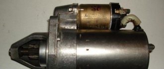
CHANGING THE IGNITION SYSTEM MODULE
When repairing the ignition module does not produce positive results, all that remains is to look for and install a new device. Most mechanics recommend choosing a “GM” device as a very reliable product. Its cost varies in different regions, but is close to 2000 rubles. Replacing the ignition module can be done independently, there are no special features, and no special devices are needed. For work, prepare:
- Ignition unit for replacement;
- Key to "13";
- Rags.
The work can easily be done in a garage or on level ground. Work order:
- Open the engine compartment hood and disconnect the battery terminals. It is quite enough to remove the terminal only from the negative side.
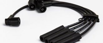
- After this, we remove the high-voltage wires from their installation locations. You need to remember where which wire was located. If you doubt your abilities, then make marks. Wires cannot be swapped. A new spare part can be damaged.
- At the next stage, carefully disconnect the connector with wires from the module. Use the key set to “13”, which unscrews the three nuts securing the device to the motor.
- When the nuts are removed, the device is removed from the engine.
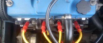
Now they use rags to wipe the installation area and around it. Carefully inspect the new device and begin installing it. It is carried out in the reverse order to removal. Once again I would like to remind you of the importance of installing high-voltage wires in their places. If difficulties still arise, then take another look at the block. It shows the numbers of high-voltage wires.
Numbers - the order of arrangement of explosive wires in the module
It should be noted that on sale you can still find old-style ignition modules that do not have wire numbers marked on the high-voltage terminals. If you purchased just such a device, be careful when installing it.
Video “Visual guide to replacing MH”
The STO TONN channel presented a visual aid for replacing the ignition module on a domestic VAZ 2114 car.
It cannot be said that the VAZ 2114 is a very modern car filled with electronics. However, the list of sensors used that are connected to the electronic control unit is quite impressive on the fourteenth.
Each of these devices is responsible for certain functions and collects data transmitted to the main computer of the car. This way, the ECU controls the entire process and makes appropriate changes, so that the driver does not have to look for the reasons for the failure or insufficiently efficient operation of a particular unit.