Repair / From Ekaterina Larina
- Performance diagnostics
- Fuel pump repair
The fuel pump does not pump
- Replacing the rod
- Cleaning the fuel pump
- Using the repair kit
- Video: repairing a VAZ 2106/07 fuel pump
- Dismantling the pump
In the ranking of the most capricious components of a car, the fuel pump occupies one of the first places. Therefore, any car enthusiast needs to know the basics of diagnosing the performance of the pump and the procedure for repairing and replacing it.
What fuel pumps were equipped with classic VAZ models?
Classic VAZs include all models of the Zhiguli family, produced from 1970 to 2012 and their modifications:
- VAZ 2101;
- VAZ 2102;
- VAZ 2103;
- VAZ 2104;
- VAZ 2105;
- VAZ 2106;
- VAZ 2107.
Depending on the year of manufacture, the engines of these vehicles were equipped with different fuel systems. In all the first Zhiguli models, the fuel mixture was injected into the cylinders using a carburetor, and the fuel was supplied by a mechanical fuel pump. The latest modifications of the VAZ 2104, 2105 and 2107 had an injection system and an electric fuel pump.
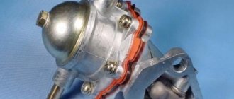
Carburetor cars of the Zhiguli family were equipped from the factory with mechanical fuel pumps of the diaphragm type DAAZ 2101 (catalog number 1106010) produced by the Dimitrovgrad Automotive Unit Plant. Thanks to their simple design, reliability and maintainability, they have proven themselves well not only on the “classics”, but also on cars of the Sputnik and Samara families, which were equipped with their modified versions.
Carburetor VAZ 2101–2107 were equipped with DAAZ mechanical fuel pumps
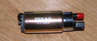
Injection Zhiguli models were equipped with domestically produced electric fuel pumps. They were produced by the Pekar and Utes enterprises under catalog number 21073–1139009. The latest modifications of the Zhiguli were equipped with products (catalog number 2112–1139009). The same devices were installed on all models of the Samara and Lada families.
Injection models of classic VAZs were equipped with electric fuel pumps “Pekar”, “Utes”, “Bosch”
Reasons for lack of submission
The owner of a VAZ 2106 is faced with a choice - which path to take in order to restore the functionality of the pump.
The first option is the simplest and most reliable
, but expensive in terms of cost. Any decent service station has equipment that, in a minimum amount of time, will not only measure the pressure at the inlet and the vacuum at the outlet of the fuel pump, but also identify the part causing defects in the operation of the equipment.
Second
The option is not the simplest, not so fast, but practically free, except for the time spent on it - do all the diagnostic and repair work yourself in the garage.
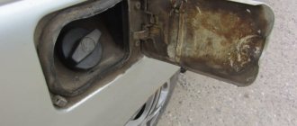
Where is the fuel pump located on 2106, 2107 and other models
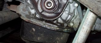
The location of the fuel pump on carburetor and injection classic VAZs is different. In the first, it is installed on the left (as viewed from the passenger compartment) on the engine cylinder block on a special boss, and is attached to it using studs through a heat-dissipating ebonite spacer. The mechanical fuel pump is driven from the engine intermediate shaft through an eccentric and a pusher (rod).
The mechanical fuel pump on the classic is mounted on a special boss on the engine cylinder block
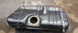
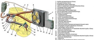
In injection Zhiguli cars, the pump is included in the design of the fuel module. It is located inside the gas tank. The design of an electric pump consists of a DC electric motor and a specially shaped impeller mounted on its shaft. The electric motor is powered from the vehicle's on-board network. The electrical circuit of the device is protected by a separate fuse and relay.
The electric fuel pump on injection classic models is installed in the gas tank
Removal and installation
The process of removing and installing the fuel pump is performed in several operations.
The fuel pump is secured using two studs and nuts with the simultaneous installation of gaskets. To remove the fuel pump, it is necessary to disconnect the discharge and supply pipelines and unscrew the fastening nuts.
When removing the pump, it is necessary to carefully disconnect the heat-insulating and sealing gaskets without damaging them.
After the repair, it is necessary to perform an installation, which has a number of features. First of all, gaskets are installed: sealing gaskets with a thickness of 0.7–0.8 mm, then heat-protective and insulating gaskets 0.27–0.33 mm. It is necessary to comply with the condition that the pusher is slightly higher than 0.8 mm; if it does not peek out, then replace the gasket 0.7–0.8 mm with 0.27–0.33 mm.
If the pusher protrudes above the gaskets by more than 1.3 mm, replace the 0.7–0.8 mm gasket with a thicker one, 1.2–1.3 mm thick. It is also necessary to follow the procedure when a 0.27–0.33 mm gasket should be installed between the heat-insulating gasket and the body.
The set of gaskets between the pump and the cylinder block should allow the pusher to extend to a distance of 0.8–1.3 mm. After installing the fuel pump, it is secured and the fuel lines are connected.
The engine is started and the condition and functionality of the fuel pump and pipelines are checked for the presence of gasoline leaks.
Photo instructions
Fittings
Replacing the fuel pump
Removing the fuel pump
The process of removing and installing the fuel pump is performed in several operations. The fuel pump is secured using two studs and nuts with the simultaneous installation of gaskets.
To remove the fuel pump, it is necessary to disconnect the discharge and supply pipelines and unscrew the fastening nuts.
After the repair, it is necessary to perform an installation, which has a number of features. First of all, gaskets are installed: sealing gaskets with a thickness of 0.7–0.8 mm, then heat-protective and insulating gaskets 0.27–0.33 mm. It is necessary to comply with the condition that the pusher is slightly higher than 0.8 mm; if it does not peek out, then replace the gasket 0.7–0.8 mm with 0.27–0.33 mm.
If the pusher protrudes above the gaskets by more than 1.3 mm, replace the 0.7–0.8 mm gasket with a thicker one, 1.2–1.3 mm thick. It is also necessary to follow the procedure when a 0.27–0.33 mm gasket should be installed between the heat-insulating gasket and the body.
The engine is started and the condition and functionality of the fuel pump and pipelines are checked for the presence of gasoline leaks.
Photo instructions
The preferred option for car enthusiasts who do not want to engage in such repair work may be to purchase an electric fuel pump for the VAZ 2106, which is more durable and reliable in operation.
Diagnostics and replacement of the electric fuel pump on cars of the Zhiguli family
In injection engines of classic VAZs, the fuel pump may lose its functionality both due to problems with the power supply to it and due to a malfunction of its electric motor. In the first case, the situation can be corrected by diagnosing and repairing the electrical circuit of the device. But if the electric motor of the pump fails, only replacing it will help.
Checking the protection devices for the electrical circuit of the fuel pump on injection VAZs of the Zhiguli family
If there is a problem with the electrical equipment of the fuel pump circuit, it usually does not turn on at all. Turn on the car's ignition without starting the engine and listen. First, you should hear a click from the relay, and then a characteristic “squeal” emitted by the pump’s electric motor. If you don’t hear anything like this, start diagnosing with the electrical circuit of the device.
The pump circuit is connected to the on-board network via a separate relay, and its protection is provided by a fuse. Both of these devices are located in the vehicle's optional mounting block. You will find it under the glove box. It contains 3 relays and 3 fuses. The fuel pump relay (indicated R2 in the diagram) is located in the middle, and the fuse (F3) is to the left of it. We pull the fuse out of its seat and check it by “ringing” it with a tester. If a malfunction is detected, we replace it, not forgetting to comply with the rating (15 A).
You can check the functionality of the relay by installing a known working device in its place. Instead, replace it with the relay located to the right of the one being diagnosed, which is responsible for the radiator fan circuit. If this option does not suit you, turn on the ignition and measure the voltage between the pink wire going to the relay and the vehicle ground. The device should show 12 V. This means that the device is powered. After this, you need to connect the pink wire with the gray one at the relay terminals. So we will connect the fuel pump directly to the battery. If it works (that same “squealing” sound will be heard), simply replace the relay.
The fuel pump relay is located in the middle (R2), and the fuse is located to the left of it (F3)
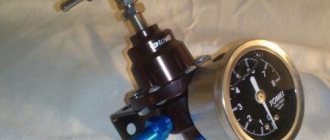
Checking the fuel pressure in the system
The main indicator of the operation of a fuel pump is the pressure it creates in the system. If the device turns on, pumps fuel, but the engine runs intermittently, take the time to check the pressure. To do this, you will need a pressure gauge with a measuring range of 5–7, equipped with a gas-resistant hose and a threaded fitting (if there is no special one, you can use a regular tire pressure gauge). The sequence of actions is as follows:
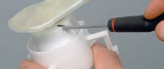
- On the fuel rail we find a fitting closed with a plastic cap. Unscrew the cap and connect the pressure gauge hose to the fitting. If your device is not equipped with a special threaded fitting, the hose can be secured to the “nipple” using a small clamp.
Pressure connection - We start the engine and look at the instrument readings at idle. The pressure in the system should be between 2.8–3.2 atmospheres. Otherwise, the fuel pump is faulty.
The pressure in the ramp should be 2.8–3.2 atmospheres - Just in case, let's check the pressure regulator (also located on the ramp).
Without disconnecting the pressure gauge, disconnect the vacuum hose from it. The pressure should rise by 0.2–0.7 atmospheres. The pressure has not increased - we are replacing the pressure regulator. When removing the vacuum hose from the regulator, the pressure should drop by 0.2–0.7 atmospheres
Performance diagnostics
The main reasons for checking the performance of the pump are as follows:
- significant reduction in fuel supply to the carburetor;
- reduction in engine performance;
- car jerking while driving.
Before diagnosing pump malfunctions, you need to make sure that other elements of the fuel system are working - carburetor, fuel hoses, filters, etc.
For diagnostic work you will need:
- open-end wrench 10;
- flat screwdriver.
The work is performed in the following sequence.
- On a car with a cold engine, the hood opens.
- Use a screwdriver to loosen the clamp securing the pump inlet pipe.
Use a screwdriver to loosen the clamp securing the inlet pipe. - The pipe is removed and a plug (bolt of a suitable size) is installed in its hole to prevent fuel leakage.
- The fuel supply hose is disconnected from the carburetor fitting and lowered, and a plug is placed in the hole.
- By pressing the manual pump lever, the resistance of the diaphragm spring is checked - the pump should make retracting sounds. If there is no resistance and no characteristic sounds, then the pump is faulty.
My car won't start. What to do? – Signs, reasons, your actions
Fuel pump in VAZ 2110/2112: self-diagnosis and replacement
Car owners have asked us at the service station many times with this question. There could be a lot of reasons. Today we will look at those that you can diagnose yourself without special tools and devices. Let's look at the signs that can be used to determine by hearing or appearance the failure of one or another unit in a car. I’ll tell you what a simple car owner can check and fix without going to a car service center.
Some of them will seem banal, even primitive; they can mislead an untrained driver, and the service station will charge him money for this. Beginners know little about them, but experienced car enthusiasts will find it useful to refresh their memory. You can already start throwing rotten tomatoes at me, but I’m sure that not all of the commentators will be able to independently determine why their car won’t start.
TNND device
TNND consists of:
- Drive shaft;
- A rotor with a certain number of blades;
- Stator;
- Distribution disk;
- Adjustable drive gear;
- Connection couplings.
Low pressure fuel pump design
When the rotor begins to move, its blades begin to move closer to the stator and, under the influence of centrifugal force, certain chambers appear. Since there is a certain voltage inside, the fuel from these chambers is sent directly to the fuel injection pump. For this purpose, special channels in the distribution disk are used. In this case, a small amount of fuel is directed to the pressure reduction valve if the pressure is created greater than that set by the system.
Since both devices are inextricably linked, to maintain the necessary conditions, a fuel drain choke (in the form of a nozzle) screwed into the high-pressure pump is used. Thus, the design of this part makes it possible to create the necessary conditions in the chambers depending on the speed of the drive shaft. This design is suitable for diesel engines, but there are other types, which will be discussed further.
Signs of fuel pump defects
Many car enthusiasts know that the fuel pump is a component of the “six” fuel system that repeatedly malfunctions or, in simple words, it malfunctions. Reasons: low-quality gasoline, clogged and lately replaced fuel filter, high loads on product parts, exposure to active ingredients due to oil and antifreeze leaks, low-quality rubber components, etc.
The main malfunctions of the fuel pump are a violation of the sealed conditions of the fuel pump, gasoline leakage and “the VAZ 2106 fuel pump does not pump,” i.e. failure of the product membrane. In this case, repairs “in the field” are possible, when drivers have, for example, to install high-density cellophane instead of the standard membrane, which allows them to get to their destination. A more civilized repair of the fuel pump for the “six” is to purchase a repair kit for the fuel pump and replace worn parts.
Scheme of work
The movement of the diaphragm starts the mechanism. Due to the fact that the direction of its movement is up and down, when it moves down, a vacuum is formed above it and the inlet valve opens, through which gasoline passes, subsequently entering the recess of the diaphragm, having previously passed through the filter. When the diaphragm moves up, pressure is generated, stimulating the closing of the intake valve, then the exhaust valve opens and gasoline flows through the fuel system.
Design of an automobile electric fuel pump 1 - outlet fitting; 2 - check valve; 3 - electrical terminal; 4 - collector; 5 — brush holder with spring and brush; 6 - stator permanent magnet; 7 fixed axis for the electric motor armature and for the pump rotor; 8 — electric motor armature; 9 — coupling fork; 10 - centrifugal roller; 11 — supercharger cover with outlet slot; 12 — supercharger stator with an eccentric cylindrical cavity; 13 — supercharger rotor with five centrifugal rollers; 14- supercharger bottom with inlet slot; 15 — inlet; 16 — fuel coarse filter mesh; 17 — outlet; 18 — relief valve; 19 — recess in the bottom of the gas tank.
How to adjust the fuel pump drive?
Using the example of the fuel pump of the engine power supply system 21083 of the VAZ 21093 car, we will adjust the fuel pump drive.
On a VAZ 21093 car, the fuel pump is mechanical, driven from the camshaft through a pusher. The performance of the fuel pump, and therefore the normal operation of the engine, directly depends on how correctly the fuel pump drive is adjusted.
If there are dips, jerks, twitches in the engine operation, throttle response has decreased at medium and maximum loads, or no fuel is supplied to the engine at all, it makes sense to adjust the fuel pump drive.
The essence of the adjustment is to change the amount of minimum protrusion of the pusher relative to the plane of the heat-insulating spacer and gaskets of the gas pump, in order to ensure its optimal performance.
Adjusting the fuel pump drive of a VAZ 21093 car
Removing the fuel pump from the car engine
In this case, the heat-insulating spacer and gaskets remain on the engine.
Rotate the crankshaft until the pusher protrudes to a minimum
The moment of minimum protrusion can be determined visually by placing a finger on the pusher. Using a large slotted screwdriver, we slowly rotate the crankshaft by the flywheel teeth in the hatch on the clutch housing, and use our finger to control the movement of the pusher into the spacer.
We measure the minimum protrusion of the pusher
There is a special device for these purposes (67.7834.9506), but you can get by with a caliper. In the image below, the measurement was made generally using a conventional drill (1 mm). The minimum protrusion of the pusher should be in the range of 0.8 - 1.3 mm.
If the obtained value is less than the required one, the performance of the fuel pump will be low. As a result, the negative consequences for engine operation described above occur. Otherwise (the value is greater than normal), fuel “overflow” occurs in the carburetor, since the fuel pump produces high fuel pressure, and the valve in the float chamber is not designed for such a load, fuel “overflow” will occur.
Adjusting the minimum protrusion of the pusher
You can adjust the minimum protrusion by selecting gaskets for the fuel pump. There are two of them: between the heat-insulating spacer and the engine (0.27-0.33 mm), between the fuel pump and the heat-insulating spacer (0.79-0.80 mm).
If the protrusion of the pusher is insufficient, replace the gas pump-spacer gasket with a thinner one similar to the spacer-engine gasket (0.27-0.33 mm). If the protrusion is greater than normal, then install a thicker gasket for the fuel pump-spacer (1.10-1.30 mm). Such a thick gasket can be taken from the fuel pump repair kit or cut from a paronite sheet of the required thickness. The gasket between the heat-insulating spacer and the engine does not change and is not involved in adjustment.
If it is impossible to adjust the fuel pump drive by selecting gaskets, it is necessary to replace the pusher, since it can simply be worn out during long-term operation.
Notes and additions
The performance of the fuel pump of a VAZ 21093 car is 1 liter per minute at an engine speed of 2000±40 rpm and an air temperature of 20 degrees. The fuel injection pressure is 0.21-0.30 kgf/cm².
Source
Lada 2106 2001 - self-repair
Comments 8
Participate in the discussion can only registered users.
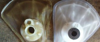
The problem of gasoline evaporation and the formation of an air lock in the gasoline pump lies in the design of the gasoline pump itself. In the DAAZ there is a “parasitic” volume in the hemispherical lid, which serves as a catalyst for the formation of a plug, but in the baker there is no such volume, and the filter itself is mounted in the inlet fitting of the pump, but the baker has only one diaphragm and there is no safety fuel discharge in case of a membrane break.
mm interesting, but sometimes you also get up, the fuel pump heats up and you spray it with water, you wait and then you drive on)
I don’t agree about Pekar. It’s been working for about five years now and I don’t know any problems with it, the only drawback is that the outlet fitting is poorly flared, and it has never failed in any heat or cold! And such b.n. with round lids I changed a lot until I got tired of throwing away money. Almost everyone had problems in the heat, many had membranes leaking after a short period of use. With the Baker I forgot about all these shortcomings, only with a normal Baker, and not a Chinese ga.n!
Then you were lucky with Pekar, but I came across China twice :/
There was a lot of China on the market then and even more so now. It’s not difficult to distinguish between a normal one and a Chinese one, it’s very noticeable by the casting and coloring of the case, at least five years ago I bought it that way.
Interesting, this is the first time I’ve seen such a system, I’ve mostly only heard it in words. Is it working fine at the moment? On what principle is the return line built?
So far everything is amazing with this system. The car runs on gas-gasoline. During the transition to gas, the pump turns off automatically so as not to run idle, and when gasoline is turned on, it also automatically starts pumping. freed from constantly being under the hood for manual pumping. return from the Solex carburetor to the tee in front of the filter.
Full version of the site