What are the reasons for the charging failure, how to fix the problem on the road or in the garage - this is discussed in this manual.
The electrical circuit of the LADA Niva 4×4 is built according to a classic layout and has undergone virtually no changes since the start of production. Why, knowing its weak points and moving from the obvious to the complex. You will quickly find the root cause.
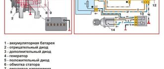
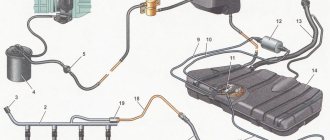
Generator connection principle, drawing:
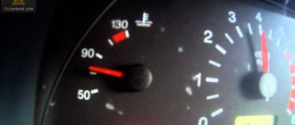
Basic information about the state of the charger can be obtained from the behavior of the instrument cluster - flashing of the indicator, emergency operation of electrical equipment (headlights, interior lighting, heater) and the engine.
Niva 2121 / Lada 4×4 - fuses and relays
Niva SUV is known under the names VAZ-2121
(VAZ 21213, VAZ 21214) and since 2006 as
Lada 4x4
.
Produced from 1977 to the present with various body modifications, mainly 3- and 5-door station wagons with gasoline engines ( carburetor, injection ). In our publication you will find a description of the fuse and relay blocks of the Niva 2121 with their locations, photo examples of execution and block diagrams. Note the fuse responsible for the cigarette lighter. In conclusion, we will offer a Niva electrical diagram for downloading.
Due to the long production period and the huge variety of designs, there is no one general description of the fuse and relay block for Niva 2121. In your car, the purpose of the fuses may differ from those presented.
All main fuse and relay boxes are located in the passenger compartment, under the instrument panel on the driver's side.
Generator operation
The Niva Chevrolet generator is responsible for the reliable and high-quality operation of the electronics system. The owner should identify possible malfunctions in a timely manner and carry out high-quality repairs, since the functioning of all lighting devices depends on its good condition. This also affects the battery charge. A continuous supply of current is provided by a generator.
Although it has small dimensions, the generator is very durable. To prevent damage and failure of the car regulator, the owner must follow the rules for operating the car.
Particular attention should be paid to how the Chevrolet Niva generator works. Malfunctions that led to a malfunction in its operation can be determined using automotive diagnostics. And the repair depends entirely on the degree of complexity of the breakdown.
Engine control system fuse box
Designation
p, blockquote 10,0,0,0,0 —>
| 1 | 15A 1* ECM sensors Starter relay Canister purge valve |
| 1 | 7.5A 2* Controller |
| 1 | 3: Electric fuel pump relay (contacts) Electric fuel pump |
| 1 | 30A 4.5* Cooling fan |
| 2 | 15A 1* Injectors Ignition coils ECM controller Right electric fan relay Left electric fan relay |
| 2 | 15A 2* Electric fuel pump relay (contacts) Electric fuel pump |
| 2 | 30A 3* Reserve |
| 2 | 30A 4.5* Cooling fan |
| 3,4 | 30A 1* Electric fans (right, left) Right electric fan relay Left electric fan relay |
| 3 | 15A 2* Main relay |
| 3 | 15A 3* Controller |
| 3 | 15A 4* Ignition coil, power supply for fan relay control, controller, injectors |
| 3 | 15A 5* Ignition relay |
| 4 | 15A 3* Main relay Electric fan relay (winding) Electric fuel pump relay (winding) Vehicle speed sensor Canister solenoid valve Oxygen sensor Mass air flow sensor Controller |
| 4,5 | 30A 2* Electric fan relay (winding) (right, left) Electric fan motor (right, left) |
| 4 | 15A 4* Mass air flow sensor, phase sensor, heating oxygen sensor (two), canister purge valve, DS |
| 4 | 15A 5* Electric fuel pump |
| 5 | 15A 1* Electric fuel pump Electric fuel pump relay |
1* - 2014-2016, 2* - 2010-2012, 3* - 2007-2008, 4* - Cars with Bosch ME17.9.7/M74 controllers, 5* - Cars with 7.9.7+ controllers.
Main fuse box
p, blockquote 14,0,0,0,0 —>
| 1 | 16A Heater fan electric motor Relay (winding) for headlight wipers and electric motors for headlight wipers in all wipe positions except the initial Relay (winding) for turning on the rear window heating Electric motors for the rear window cleaner and washer Electric motor for the windshield washer |
| 1* | 16A Lamps Horns Socket Lighter Brake light |
| 2 | 8A Relay and electric motor of the windshield wiper Turn signal lamps and relay-interrupter for direction indicators and hazard warning lights (in turn signal mode) Turn signal indicator lamp Tail lights (reversing light lamps) Generator excitation winding (when starting the engine) Differential lock activation indicator lamp in the transfer case Indicator lamp for turning on the parking brake Indicator lamp for the emergency condition of the service brake system Indicator lamp for insufficient oil pressure Fluid temperature indicator in the engine cooling system Fuel level indicator with a warning lamp for fuel reserve Indicator lamp for battery charge Indicator lamp for closing the carburetor air damper Tachometer Electric heater motor Relay headlight cleaners and washer (with the headlight cleaner and washer switch button not pressed) Headlight wiper electric motors in all brush positions except the initial one* |
| 3 | 8A Left headlight (high beam lamp) Indicator lamp for turning on the high beam headlights |
| 4 | 8A Right headlight (high beam lamp) |
| 5 | 8A Left headlight (low beam) |
| 6 | 8A Right headlight (low beam) |
| 7 | 8A Left front light (side light) Right rear light (side light) License plate lights Indicator lamp for turning on side lights |
| 8 | 8A Right front light (side light) Left rear light (side light) Instrument lighting lamp Heater control lever backlighting lamp Cigarette lighter lighting lamp Illumination lamps for switches and switches |
| 9 | 16A Direction indicators and relay-breaker for direction indicators and hazard warning lights Rear window heating element and relay (contacts) for its activation |
| 9* | 8A Warning lamp and oil pressure gauge Coolant temperature gauge Fuel level gauge with reserve warning lamp Parking brake warning lamp Brake fluid level warning lamp Turn indicators and corresponding warning lamp Carburetor choke control warning lamp Battery charge warning lamp Carburetor shut-off valve Tachometer Rear lights (reverse light) Differential lock warning lamp Turn signal relay interrupter Heated rear window (control circuit) |
| 10 | 16A Sound signal Cartridge for connecting a portable lamp Interior lamps Tail lights (brake lamps) |
| 10* | 8A Voltage regulator Generator excitation winding |
| 11 | 8A Turn signal lamps and relay-breaker for turn signals and hazard warning lights (in hazard warning mode) Rear fog lamp |
| 12 | 8A Daytime running light relay, daytime running light lamps |
| 12* | 8A Headlight cleaner and washer relay (with the headlight cleaner and washer switch button pressed) Headlight washer electric motor Headlight cleaner electric motors at the moment of start-up and when the brushes pass the initial position |
| 13 | 8A Rear lights (fog light lamps) Electric motors for headlight cleaners at the time of start-up and when the brushes pass the initial position Relays (contacts) for headlight cleaners Electric motor for headlight washers |
| 14 | 16A Cigarette lighter |
| 15 | 16A Backup Heated rear window (power circuit) |
| 16* | 8A Hazard warning switch and direction indicators in hazard warning mode Rear window wiper and washer |
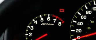
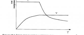
The battery charge indicator light is constantly on
The phenomenon indicates that the generator has stopped its normal operation; at this moment, the BS is powered by the battery. With a normally charged battery, you have 30-40 km of mileage left to get to the repair site.
Disconnect consumers as much as possible, arm yourself with a multimeter and a set of keys.
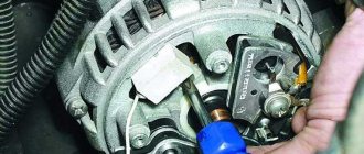
Belt break
Pay attention to the presence of a belt on the pulleys of the water pump and generator. To return it to its place, you will need 17 or 13 socket wrenches, depending on the year of manufacture of the car, as well as a strong flat-head screwdriver.
Disconnect the HF position sensor (for example, on 21213,21214).
Loosen the nuts securing the tension bar and slide it to the side towards the cylinder block.
Place the belt on your seat.
Upon completion of installation, adjust the tension, controlling the deflection when pressing with your thumb on the belt gap between the generator and pump pulleys - 10-15 mm, pump and crankshaft - 12-17 mm.
Failure to comply with this requirement may result in the belt slipping with further damage and rupture.
Burnout of wires, poor contact in the circuit
If the circuit opens at terminals B, V and Ш, tighten the nuts or replace the terminals with new ones.
Engine Control Relay Box
It is located under the main fuse box and consists of 5 relays and 1 fuse.
Electrical diagram of the block
Decoding
p, blockquote 21,0,0,0,0 —>
- Ignition relay
- Main relay
- Right cooling fan relay
- Left cooling fan relay
- Fuel pump relay
- Fuel pump fuse F5 15A
The only difference between Nivas with injection and carburetor systems is due to the fact that the engine control relay unit can be located under the hood of the car in a specially designated compartment.
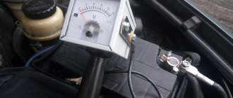
How to check if the battery is charging
Before looking for a fault in the charging circuit, it is necessary to find out whether this very undercharging actually exists. After all, the problem could be:
- in charge indication circuits;
- in a faulty battery.
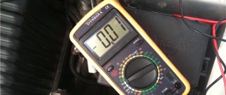
Healthy! To check, we use a DC voltmeter with a measurement limit of 20 V or a multimeter (tester). Both pointer and digital devices are suitable. The accuracy of both will be sufficient.
We connect a voltmeter or multimeter turned on in the DC voltage measurement mode to a limit of at least 20 V. We start the engine and raise its speed to 1,000 per minute. If the voltmeter shows a voltage in the range of 13.5-14.2 V, then the charging circuits are OK. The fault is with the charging indication elements that mislead us, or with the battery.
In the first case, we check the control circuits (their circuits and testing algorithm will be described below), in the second case, we test the battery using a load fork.
Additional relay block
This block is located above the gas pedal.
p, blockquote 26,0,0,0,0 —>
- Rear fog lamp relay
- Rear window heating relay
- Low beam relay
- High beam relay
A little higher, above the block, a relay can be installed - a breaker for the turn signals and hazard warning lights.
Separate fuses and relays can be installed under the hood: on cars with ABS, on the left side of the engine compartment near the ABS hydraulic unit, a block with fuses is additionally installed that protect the elements of the anti-lock brake system and the starter relay not far from the starter itself.