The most basic function of the generator is to charge the battery and power the electrical equipment of the engine.
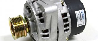
Therefore, let’s take a closer look at the generator circuit , how to connect it correctly, and also give some tips on how to check it yourself. A generator is a mechanism that converts mechanical energy into electrical energy. The generator has a shaft on which a pulley is mounted, through which it receives rotation from the engine crankshaft.
- Accumulator battery
- Generator output "+"
- Ignition switch
- Generator health indicator lamp
- Noise suppression capacitor
- Positive power rectifier diodes
- Negative power rectifier diodes
- Generator "mass"
- Field winding diodes
- Windings of three stator phases
- Field winding power supply, reference voltage for voltage regulator
- Field winding (rotor)
- Voltage regulator
A car generator is used to power electrical consumers, such as the ignition system, on-board computer, car lighting, diagnostic system, and it is also possible to charge a car battery. The power of a passenger car generator is approximately 1 kW. Car generators are quite reliable in operation because they ensure uninterrupted operation of many devices in the car, and therefore the requirements for them are appropriate.
Carburetor engines
The connection diagram for the VAZ-2107 generator (carburetor and injector) depends on the year of manufacture of the car. The first carburetor models had a G-222 generator installed. The same device can be found on commercially produced VAZ-2105 and VAZ-2104 models with a carburetor injection system.
The maximum output current for such an installation is 55 amperes. But in recent years, cars with fuel injection systems have become widespread. Its use implies a large current consumption, so it is necessary to use a generator with a high current to ensure a normal charge level and power supply to all consumers.
DIY Generator Connection Guide
The reason for replacing a VAZ 2107 generator with an injector or carburetor may be:
- burnt windings;
- an interturn short circuit has occurred;
- mechanical damage to the housing;
- malfunction of a three-level regulator, etc.
The generator replacement procedure consists of removal, installation and connection.
- First of all, we de-energize the car by removing the negative terminal from the battery.
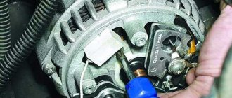
- Disconnect the connector from the generator set.
Disconnecting the connector from the unit - Having removed the protective cover, you need to disconnect the terminal with a “10” key and remove the wire.
- After loosening the generator, you need to remove the drive belt.
- Using a “17” wrench, unscrew the nuts and remove the adjusting bar.
- After unscrewing the lower fastening nut, remove the bolt and bushing.
- We dismantle the generator.
Unit removed for repair
The generator set is installed in the reverse order. Before installing the unit, you need to thoroughly study the connection diagram of the 2107 generator with an injector or carburetor, as well as the electrical connection diagram. In this case, you need to pay attention to the difference between 37.3701 and G222.
After installation, you need to adjust the belt tension. To adjust the belt tension, you need to loosen the two bolts securing the unit. Using a pry bar, tighten the belt and secure it in this position with a nut on the adjusting plate. Then you need to check the degree of tension. To do this, you need to press the belt in the gap between the pulleys.
The deflection should be in the front from 10 to 17 mm. The procedure should be repeated until the desired value is achieved. After tensioning, all fastening nuts are finally tightened. At this point, the connection of the unit can be considered complete.
Modern cars are equipped with a large number of electronics, so the generator must be powerful to provide power to the on-board network and the operation of network elements. Therefore, you need to carefully monitor its technical condition.
Injection engines
On injection engines, generator sets 5142.3771 or similar are used. They have increased energy, the maximum current is about 80-90 A, it all depends on the design option. Cars of the seventh series and similar models are good because they are like a designer set. You can install almost any generator on them, similar in design to the “native” one.
For tuning, installations with an output current of 100 amperes and higher are used. But the use of such devices is justified only if many powerful consumers are connected to the electrical equipment. Regardless of the design, the generators produce alternating current; a voltage regulator, capacitor and diode block are installed in the housing.
Common breakdowns
Generator faults can be electrical or mechanical. These include:
- loss of functionality of the voltage regulator;
- breakdown of the rectifier unit (diode bridge);
- short circuit of stator windings;
- current short circuit in the rotor winding;
- wear of bearings and brushes.
Read also: Steel 40x carbon content
Voltage regulator
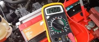
The purpose of this unit is to normalize the voltage before feeding it into the automotive electrical circuit. You can check the serviceability of the regulator by checking the voltage that it supplies to the battery terminals. This indicator depends on the model and brand of the vehicle and varies between 13.5-15.5 V. Therefore, you should find out in advance what voltage your particular type of regulator produces. This can be done by studying the manual for using the machine. For example, you can take a VAZ 2107 or 2110 car, since these vehicles have the most typical faults associated with the integral and relays.
Using a Multimeter
To check the VAZ 2110 generator with a multimeter, you need to switch the device to voltmeter mode. Then you need to connect its probes to the battery terminals. The most important thing is to observe the polarity and turn off the car engine. The voltage normally varies from 12 to 12.8 V. Next, the procedure should be repeated, but with the engine running. The voltage readings should rise to 13.5-15.5 V. Lower and higher voltage values indicate a malfunction of the generator.
Checking the generator without removing it from the car
A bridge of diodes performs the functions of a kind of alternating current converter. It contains three negative and three positive diodes.
Before checking the bridge, you need to disconnect all the wires coming from it and from the voltage regulator. You also need to remove the ground anchor from the battery in advance. First you need to check the rectifier for short circuits. We activate the ohmmeter mode on the multimeter and connect the red (positive) probe to the positive contact of the diode bridge, and the negative probe to the surface of the housing of the generator itself. If the rectifier is fully operational, then the readings of the measuring device will go to infinity. In other cases, the rectifier will be inoperative.
Testing of stator and rotor windings
A common breakdown of a car generator is a short circuit in the windings. It occurs when current surges are too intense, brushes wear out and liquid gets in.
So, you need to remove the rotor and find a pair of slip rings on its structure that will need to be ringed. Having started the ohmmeter mode on the multimeter, we connect the probes to these rings. Normal resistance is 2-6 ohms. If you get large values, then there is a loss of contact between the slip rings. If the device shows lower values, then an interturn short circuit has occurred.
Then you should measure the resistance between zero and the terminals of the windings. The normal value is no less than 0.3 Ohm.
Wear of brushes and bearings
If you have already disassembled the generator, then it is advisable to check the condition of the brushes. They can wear out or break due to misalignment of the rotor shaft. If the brushes are damaged, they should be replaced with new ones.
Inside a car alternator there is a pair of bearings. One is fixed on the rotor shaft, the other is in the center of the cover. The whistling and hum of the generator when the engine is running is a clear sign of bearing wear. In this case, the generator housing can become very hot. If you notice such signs, it is better to replace the bearings immediately, otherwise you may encounter more serious problems.
You can check the bearing by removing the belt from the generator and trying to rotate its shaft with your own hand. If the part rotates freely and easily, then everything is in order. If it is difficult to rotate the rotor, then you should not delay replacing the bearings.
How to check the generator for performance? Self-check and repair of the generator
A generator is a typical electrical station that provides energy to all engine systems: power, cooling, ignition, so its failure will inevitably lead to other malfunctions. To prevent breakdowns, you need to systematically diagnose it, and if problems cannot be avoided, repair it immediately.
In this article we will talk about how to check the generator for performance without resorting to the help of professionals. But before that, let's look at the symptoms of its possible defects.
Read also: Why knives become dull
Cars before 1986
The G-222 generator was used in cars. The connection diagram for the VAZ-2107 is almost the same as on later models. But there are features, among the main ones - there is a control lamp indicating battery charging. Moreover, it worked using an electromagnetic relay.
When the ignition is turned on, power is supplied from the lock through the instrument panel fuse to the electromagnetic relay of the battery charge lamp and the coil contact. The second contact of the coil is connected to the center wire on the generator (the point where the three windings connect).
The electromagnetic relay has normally closed contacts, so when the ignition is turned on, the lamp lights up. But as soon as the engine starts running, the generator produces current. And a current flows through the control lamp coil, which causes the armature to attract and open the contacts.
At the same time, the power to the incandescent lamp stops and it goes out. This indicates that the battery is charging normally. Only when the power supply to the lamp stops will voltage be applied to the excitation winding and the generator will be able to return to operating mode.
How to disassemble a generator
After the generator is removed. It needs to be inspected externally. For the presence of cracks. The rotor should rotate freely. When rotating, no creaks or knocks should be heard. If the bearings jam. This also causes the generator to lose charge. In this case, the rotor slows down. The strength of magnetic flux fluctuates. As a result, the required voltage is not created.
There should be no radial or axial displacement of the rotor. This also leads to rotation inhibition.
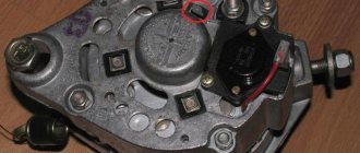
Disassembling the generator begins with removing the brush assembly. On modern generators it is designed in conjunction with a relay regulator.
Removing the brush assembly
To do this, you need to unscrew the two mounting screws with a screwdriver. Remove the relay regulator along with the brushes.
If you don't do it first. The slip rings will be damaged. Because the carbon contacts are pressed against them by springs. And upon further removal of the back cover. The contacts will catch on the rings. And they will pull them. As a result, a wiring break may occur.
Unscrewing and removing the drive pulley.
The pulley is screwed with a nut with great effort through the engraver. Therefore, it is necessary to securely fasten the pulley. To do this, put the old drive belt on the pulley. Press it tightly and squeeze it in a vice. Unscrew the nut. Using a puller, pull the pulley off the shaft. Without a puller, it may not be possible to remove the pulley. Because besides the fact that it is tightened with a nut. The shaft on which the pulley sits. Has a conical shape. Therefore, the pulley sits tightly on the pulley
Removing the diode bridge
The block with diodes is attached with screws. Contacts from the stator windings are screwed to it. After all the nuts have been unscrewed, the diode unit should be dismantled.
After the diode bridge is removed, the stator is removed
Removing the rear cover of the generator
The mounting bolts are unscrewed and the back cover of the generator is removed. The cover has a built-in bearing. This will hold the lid in place. To remove the cover, apply uniform force from opposite sides. And try to rock it. So that the bearing comes out of its seat.
Removing the front cover from the rotor
The more difficult task is to remove the front cover. Because the bearing is pressed onto the shaft. And it is secured to the body on the reverse side using a special plate. During assembly, the bearing is first installed. Then, together with the cover, it is pressed onto the shaft.
Therefore, when removing the front cover. It is very important not to damage it with the puller. The lid is fragile and breaks easily. The bearing seat should be lubricated with penetrating liquid. For example WD-40.
The most effective way to press a bearing is as follows.
It is necessary to place a wooden block on a hard surface. Turn the rotor shaft down. Holding the cover, hit the end of the shaft against a wooden block. The method is one hundred percent. But it does not require fanaticism. It is advisable not to damage the threads on the end of the shaft. So that there are no problems with tightening the nut. The blows should not be strong. The cover may be damaged.
Light sharp blows gradually press the bearing off the shaft. Do not hit the shaft from above, even through a wooden block. Because the blow will not be applied strictly along the axis of the shaft. A non-coaxial blow will not produce results and will make bearing removal difficult. In addition, there is a high probability of destruction of the front cover.
Cars manufactured in 1996 and later (carburetor engines)
The connection diagram for the G222 generator on a VAZ-2107 after 1996 differs from the previous one in one small feature - the power supply to the excitation winding has been changed. Cars have been improved, and some improvements make it possible to kill two birds with one stone - simplify the design and make the fate of the driver easier.
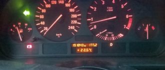
After 1996, instead of a warning lamp, they began to install a voltmeter, which more or less accurately shows the battery charge level. And if the lamp allows you to monitor only the presence or absence of voltage on the generator, then using a voltmeter the driver visually assesses the level. And if necessary, it can understand that repairs or maintenance are necessary.
Checking generator operation
You can check the functionality of the generator in several ways using certain methods, for example: you can check the output voltage of the generator, the voltage drop on the wire that connects the current output of the generator to the battery, or check the regulated voltage.
To check, you will need a multimeter, a car battery and a lamp with soldered wires, wires for connecting between the generator and the battery, and you can also take a drill with a suitable head, since you may have to twist the rotor by the nut on the pulley.
Generator circuit for injection engines
In fact, the design of the generator set is not much different from those installed on carburetor engines. Only the type of excitation and serviceability monitoring differ. The dashboard contains not only a warning lamp, but also a voltmeter; these two devices allow you to assess both the presence and level of charging. Current flows through the lamp filament and is supplied to the field winding when the engine starts. The connection diagram for the VAZ-2107 generator, regardless of the year of manufacture, implies operation in the following mode:
- When the ignition is turned on, power is supplied to the excitation winding. A magnetic field appears around the armature.
- When the crankshaft rotates with the starter, the generator armature also begins to move. With the help of movement and a magnetic field, a potential difference arises at the ends of the stator windings.
- From the windings, voltage (alternating, three-phase) is supplied to the rectifier unit, and from it to terminal “30” of the generator.
- Pin “30” is connected to the battery (positive terminal). Consequently, the entire electrical system is powered and the battery is charged.
In this case, the battery and generator G221A work in parallel. The connection diagram for the VAZ-2107 with carburetor and injection engines is almost identical, with only minor features.
Operating principle of the unit and charge indicator lamp
The operating principle of the generator 37.3701 and G222 are identical. The generator device converts the mechanical energy that appears when the crankshaft rotates into electrical energy. The resulting electricity is needed to power the on-board network and recharge the battery. Alternating current is converted into direct current with a power of 80 Amps thanks to a rectifier unit consisting of 6 diodes.
A three-level regulator maintains the voltage at the required level. After turning on the ignition, the voltage passes through the control lamp, reaches a three-level regulator, and then goes to the excitation winding.
This process can be clearly represented in the form of a diagram:
Generator wiring diagram
In the diagram, the main parts of the on-board network are marked with the following numbers:
- Battery.
- Generator set.
- Mounting block.
- Egnition lock.
- Voltmeter for measuring voltage.
- A lamp that monitors battery charging.
Power comes from three diodes, which are located in the rectifier unit. If, after turning on the ignition, the indicator light does not go out, this means that the battery is not sufficiently charged. In this case, it is necessary to check what voltage is in the on-board network. Technical characteristics of the generator: at a voltage of 13 V, the maximum current is 55/80 Amperes (video author - Vladimir Zagrivy).
If the voltage is not normal, the reason may be:
- short circuit occurring in the network;
- battery malfunction;
- breakdowns in the three-level voltage regulator;
- malfunction of the VAZ 2107 generator set with an injector.
In this case, you need to check the degree of tension of the drive belt, the condition of the bearings, and the serviceability of the three-level regulator. In addition, it is worth checking the battery charge and expiration date. Since generators 37.3701 and G222 installed on a VAZ 2107 with an injector and carburetor do not differ much, their care is the same for both models. It is enough to ensure that moisture and dirt do not get on them.
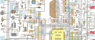
Electrical diagram VAZ-2107 carburetor
Electrical diagram of VAZ 2107, 21074 produced in 1988-2001 with generator 37.3701
- block headlights
- side direction indicators
- accumulator battery
- starter relay
- carburetor electro-pneumatic valve
- carburetor microswitch
- generator 37.3701
- gearmotors for headlight cleaners *
- Fan motor switch sensor
- engine cooling fan motor
- sound signals
- distributor
- spark plug
- starter
- coolant temperature gauge sensor
- engine compartment lamp
- low oil pressure warning sensor
- low brake fluid level indicator sensor
- windshield wiper motor
- carburetor electro-pneumatic valve control unit
- ignition coil
- headlight washer pump motor *
- windshield washer pump motor
- mounting block
- windshield wiper relay
- hazard warning and direction indicator relay
- brake light switch
- reverse light switch
- ignition relay
- ignition switch
- three lever switch
- hazard switch
- socket for portable lamp**
- heater fan switch
- additional resistor for the electric motor of the heater (stove)
- rear window heating indicator lamp
- low brake fluid level warning lamp
- signaling unit
- heater fan electric motor
- glove compartment lamp
- light switches on the front door pillars
- switches for warning lights of open front doors ***
- front door open warning lights ***
- connection block
- cigarette lighter
- watch
- instrument light switch
- diode for checking the serviceability of the low brake fluid level indicator lamp
- fuel level indicator
- fuel reserve indicator lamp
- speedometer
- turn signal indicator lamp
- carburetor choke indicator lamp
- battery charge indicator lamp
- carburetor choke warning switch
- instrument cluster
- econometrician
- light switches on the rear door pillars
- coolant temperature gauge
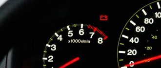
- tachometer
- parking brake indicator lamp ("handbrake")
- low oil pressure warning lamp
- high beam indicator lamp
- indicator lamp for turning on external lighting
- voltmeter
- parking brake indicator switch ("handbrake")
- outdoor light switch
- rear window heating switch with backlight
- rear fog light switch with on/off indicator *
- fog light circuit fuse
- lampshade ****
- tail lights
- level indicator and fuel reserve sensor
- connectors for connecting to the rear window heating element *
- license plate lights 2107
Wiring diagram VAZ-2107 carburetor - full view:
Possible battery malfunctions
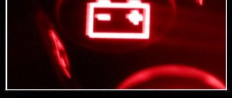
Over time, any battery becomes unusable due to wear and tear. Its service life largely depends on operating and maintenance conditions. If there is a problem, the VAZ 2110 battery light comes on on the instrument panel.
Battery indicator is on
The warning light may come on if the following problems occur:
- low electrolyte level in banks;
- Excessive heat causes the battery case to swell;
- the appearance of the smell of rotten eggs (that’s what sulfur smells like) indicates a battery leak, which is also characterized by oxidation of the terminals;
- low tension of the generator belt due to damage or wear;
- overheated fuse or poor contact in the connections of the mounting block;
- malfunction of the diode bridge, relay regulator;
- a break in the electrical network;
- oxidized contacts on the battery terminals or generator output;
- the brushes on the generator device are worn out;
- Poor contact of the ground wire.
To detect the causes of the malfunction, you need to diagnose the battery and test the entire electrical circuit of the car.
Electrical diagram of VAZ 2110
Mounting block connection diagram
P1 — relay for turning on the heated rear window; P2 - relay for turning on the headlight cleaners and washer; P3 - relay for turning on sound signals; P4 - relay for switching on the electric motor of the engine cooling system fan; P5 - headlight high beam relay; P6 - low beam headlight relay; A - the order of conditional numbering of plugs in the mounting block blocks. The outer number with the letter “Ш” in the plug designation is the block number, and the inner number is the conventional number of the plug.
Schemes of individual blocks of the seven
Power supply system
Power plant starting system
1 - starter; 2 - relay; 3 — ignition switch; 4 - battery
Ignition system
1 - generator; 2 — ignition switch; 3 - distributor; 4 - breaker; 5 — candles; 6 - coil; 7 - battery
Contactless ignition system
External and internal lighting
Windshield wipers and washers
1 — electric motors of the windshield wiper; 2 — washer motor; 3 — mounting block; 4 — ignition switch; 5 - washer switch
Cooling Fan
1 — fan electric motor; 2 - sensor; 3 — mounting block; 4 - ignition relay; 5 - ignition switch.
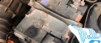
External inspection
External inspection reveals obvious damage. If necessary, spare parts are cleaned of dirt, oil and moisture. Solid particles of sand contribute to the development of bearings and brushes. It is important to know that water entering the housing can damage the varnish coating of the windings. An insulation breakdown threatens an interturn short circuit of the stator coils. Also, a layer of dirt can short circuit pin 30 to ground. A short circuit will damage the semiconductor rectifiers.
Particular attention is paid to the condition of the belt drive on the “Seven” and VAZ-2105. The belt is classified as a fast-wearing spare part. Visually determine the absence of cuts, worn out teeth, or frayed edges.
It is useful to observe the operation of the flexible transmission with the hood open. The approach of a critical state can be heard by sound. Belt slipping is one of these problems. As a result of its friction against the pulley, a characteristic whistle occurs.
Excessive wear will indicate that the damaged belt needs to be replaced. Otherwise, slipping will lead to loss of battery charging and damage to the coolant pump. The battery will run out and the motor will overheat.
The generators on the VAZ-2107 car (injector or carburetor type) have the same drive. But there is one difference - the crankshaft position sensor is not installed on the carburetor.
The degree of production increases if the tension is incorrectly adjusted. The situation is corrected by moving the body along the adjustment bar, having first loosened the fastening. Installation of the generator in place is fixed with a 17 nut and a 19 lower bolt.
The measurement is carried out by pressing on the belt. Pressure is applied with a mounting blade in the middle of the segment. The deflection between the generator and the water pump will be 12-17 mm. The right wing (directed towards the crankshaft) will bend by 10-15 mm.
Wires for connecting electrical appliances
| Connection type | Section, mm 2 | Insulation color |
| Negative terminal of the battery - vehicle ground (body, engine) | 16 | Black |
| Starter positive terminal - battery | 16 | Red |
| Positive contact of the generator - plus battery | 6 | Black |
| Generator - black connector | 6 | Black |
| Terminal on the generator “30” – white MB block | 4 | Pink |
| Starter connector “50” – starter relay | 4 | Red |
| Starter Start Relay - Black Connector | 4 | Brown |
| Ignition switch relay - black connector | 4 | Blue |
| Ignition switch output “50” – blue connector | 4 | Red |
| Ignition switch connector “30” – green connector | 4 | Pink |
| Right headlight plug - ground | 2,5 | Black |
| Left headlight plug - blue connector | 2,5 | Green, gray |
| Generator output “15” – yellow connector | 2,5 | Orange |
| Right headlight connector - ground | 2,5 | Black |
| Left headlight connector - white connector | 2,5 | Green |
| Radiator fan - ground | 2,5 | Black |
| Radiator Fan - Red Connector | 2,5 | Blue |
| Ignition switch output “30/1” – ignition switch relay | 2,5 | Brown |
| Ignition switch contact “15” – single-pin connector | 2,5 | Blue |
| Right headlight - black connector | 2,5 | Grey |
| Ignition switch connector “INT” – black connector | 2,5 | Black |
| Six-pin block of the steering column switch - “ground” | 2,5 | Black |
| Two-pin block of the steering column switch - glove box illumination lamp | 1,5 | Black |
| Glove compartment light - cigarette lighter | 1,5 | Black |
| Cigarette lighter - blue block connector | 1,5 | Blue, red |
| Rear window defroster - white connector | 1,5 | Grey |
Removing the brush assembly without dismantling the generator
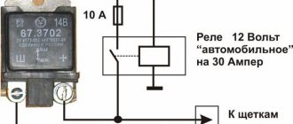
To do this, arm yourself with a short Phillips screwdriver: you need to unscrew a couple of screws that secure the brush assembly. It is better to do this from below: on the inspection hole or by placing the car on a jack. Pull out the assembly and inspect the brushes: if they protrude less than 5 mm, they need to be replaced. To check RR of different years of manufacture, you need a 12-16 V power source (you can charge a charger if it has a voltmeter and the voltage is regulated), a pair of wires and a 1-3 W 12 volt light bulb:
- For relays produced before 1996. Connect the ground (flat iron plate) PP to the negative terminal of the voltage source. Connect plus to terminals “B” and “C”.
- For relays produced after 1996 (37.3701). Connect the “B” terminal to the positive, and the “ground” contact to the negative.
Further actions are identical for both RRs. The light bulb needs to be connected to the brushes. First apply 12 V, then 15-16. The lamp should light up and then go out. If it lights up all the time, there is a breakdown in the regulator; if there is no light, there are two reasons: a break in the RR or poor contact of the brushes and rotor plates. The test will be simplified if you replace a known good relay. But what to do if there is no charger with it either?
Car wiring diagram
1 – radiator fan drive motor; 2 – relay and fuse block (mounting block); idle speed sensor; 4 – engine control unit; 5 – potentiometer; 6 – set of spark plugs; 7 – ignition control unit; 8 – electronic crankshaft sensor; 9 – electric fuel pump; 10 – tachometer 2107; 11 – lamp for monitoring the health of electronic systems; 12 – ignition system control relay; 13 – speed sensor; 14 – diagnostic connector; 15 – set of injectors; 16 – adsorber solenoid valve; 17, 18, 19 – fuse block protecting the injection system circuits; 21 – electronic fuel pump control relay; 22 – electronic relay for controlling the intake pipe heating system; 23 – intake pipe heating system; 24 – fuse protecting the heater circuit; 25 – electronic oxygen level sensor; 26 – cooling system temperature control sensor; 27 – electronic air damper sensor; 28 – air temperature sensor; 29 – pressure control sensor.
On-board network elements
The generator is an important part of the electrical system. This is the vehicle's main source of voltage. The generator converts the mechanical energy of the engine into electrical potential.
The stability of the on-board network voltage guarantees trouble-free operation of all consumers. The normal voltage level depends on the following elements:
- Generator.
- Battery.
- Relay-voltage regulator.
The electrical circuit is one whole. Failure of wiring or a short circuit can lead to failure of the entire system. The generator does not work - the battery charging current disappears. The battery is dead - you can't start the car.
The serviceability test can be carried out independently and at home. Typically, such a procedure does not involve dismantling devices on a Zhiguli-2105, 2107 car. It is necessary to have a tester that measures voltage, winding resistance, and the serviceability of diodes.
There are mechanical and electrical components of the unit. It doesn’t matter whether there is a carburetor or an injection system, the generator is checked in two directions. The following mechanical parts are subject to assessment:
- body elements;
- V-belt;
- pulley;
- bearing units;
- brush block;
- mounting bolts.
Fuse and relay diagram 2107
On newer “sevens” a block with 17 fuses and 6 relays is installed. VAZ 2107 fuses on the “new” unit protect the following electrical circuits and devices:
- Reversing lamps, heater fan, rear window defroster warning lamp and relay, rear wiper motor and rear washer pump.
- Electric motor for front wipers.
- Reserve socket.
- Reserve socket.
- Power supply for heated rear window.
- Clock, cigarette lighter, power socket “carrying”.
- Signal and radiator fan.
- Turn signal lamps in emergency mode.
- “Fog lights” and a relay that regulates the voltage of the on-board network.
- Instrument panel lamps.
- Brake light bulbs.
- Right high beam headlight.
- Left high beam headlight, high beam warning lamp.
- Side lights (rear right, front left), license plate and engine compartment lighting.
- Side lights (rear left, front right), glove compartment and cigarette lighter lamps.
- Low beam (right lamp).
- Low beam (left lamp).
The block relays perform the following functions:
- Heated rear window relay.
- Headlight cleaner and washer relay.
- Signal relay.
- Cooling system electric fan relay.
- High beam relay.
- Low beam relay.
The fuse block of the VAZ 2107 (injector) is no different from the block on the carburetor “seven”. Injection models are simply equipped with an additional relay and fuse box installed in the cabin under the glove compartment. The block includes three relays - the “main” relay, the fuel pump relay and the fan relay.
Modification of the VAZ 2110 generator
Refinement of the VAZ 2110 generator is considered a very useful improvement of the VAZ 2110, especially if you take into account the fact that many motorists, in recent times, are inclined to install additional units that consume electricity on their cars. You can increase the voltage at the output of the tens generator in various ways.
Here, as they say, who is on what is much. For example, you can purchase and install a new, more powerful generator. Modification of the VAZ 2110 generator can be solved in another way. It is, of course, cheaper, although you will still have to spend a little, but it is also more labor-intensive. The charging voltage of the VAZ 2110 generator must correspond to that stated in the instructions and be 13.9 - 14.4 volts. To increase the efficiency of the generator, you can, for example, install a KD202V diode or a 2D219B diode in it, but it must be taken into account that the breakdown voltage must correspond to 20V, and the current must not be lower than 5A.
To modify the generator of a VAZ 2110 car, you can use the installation of a regulator from a foreign car with a voltage of 14.5V on the standard voltage regulator. It is necessary to remove the “pill” from the standard voltage regulator and install a “pill” from a foreign car in its place. All the work consists of proper installation and connection. It is necessary to carefully solder the output contacts of the “pill” of the foreign car to the standard body of the voltage regulator. I think you know how to do this as well as we do, but the conclusions will have to be adjusted a little. Then, you need to screw the tablet to the regulator body. All metal connections must be “sealed” with paint (screws, nuts) so that the structure does not fall apart during the vibration of the generator.
As a result of this modification of the VAZ 2110 generator, we increased its charging voltage to 14.5V. There are probably other methods of modifying the generator, for example installing an additional generator. But we'll talk about this next time.