1200 rub. for the photo report
We pay for photo reports on car repairs. Earnings from 10,000 rubles/month.
Write:
The most basic function of the generator is to charge the battery and power the electrical equipment of the engine.
A generator is a mechanism that converts mechanical energy into electrical energy. The generator has a shaft on which a pulley is mounted, through which it receives rotation from the engine crankshaft.
Interactive image of the generator circuit. Works on mouseover
A car generator is used to power electrical consumers, such as the ignition system, on-board computer, car lighting, diagnostic system, and it is also possible to charge a car battery. The power of a passenger car generator is approximately 1 kW. Car generators are quite reliable in operation because they ensure uninterrupted operation of many devices in the car, and therefore the requirements for them are appropriate.
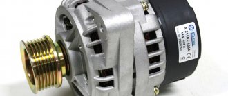
Generator device
The design of a car generator implies the presence of its own rectifier and control circuit. The generating part of the generator, using a stationary winding (stator), generates three-phase alternating current, which is then rectified by a series of six large diodes and the direct current charges the battery. Alternating current is induced by the rotating magnetic field of the winding (around the field winding or rotor). Next, the current is supplied to the electronic circuit through the brushes and slip rings.
Generator structure: 1.Nut. 2. Washer. 3.Pulley 4.Front cover. 5. Distance ring. 6.Rotor. 7.Stator. 8.Back cover. 9.Casing. 10. Gasket. 11.Protective sleeve. 12. Rectifier unit with capacitor. 13.Latch holder with voltage regulator.
The generator is located at the front of the car engine and is started using the crankshaft. The connection diagram and operating principle of a car generator are the same for any car. There are, of course, some differences, but they are usually associated with the quality of the manufactured product, the power and the layout of the components in the motor. All modern cars are equipped with alternating current generator sets, which include not only the generator itself, but also a voltage regulator. The regulator equally distributes the current in the excitation winding, and it is due to this that the power of the generator set itself fluctuates at a time when the voltage at the power output terminals remains unchanged.
The principle of operation of a car generator
Connection diagram for the VAZ 2110-2115 generator
The alternator connection diagram includes the following components:
- Battery.
- Generator.
- Fuse block.
- Ignition.
- Dashboard.
- Rectifier block and additional diodes.
The principle of operation is quite simple: when the ignition is turned on plus through the lock, the ignition goes through the fuse box, light bulb, diode bridge and goes through a resistor to minus. When the light on the dashboard lights up, then the plus goes to the generator (to the excitation winding), then during the process of starting the engine, the pulley begins to rotate, the armature also rotates, due to electromagnetic induction, electromotive force is generated and alternating current appears.
Next, the diode passes plus into the rectifier block through a sine wave into the left arm, and minus into the right arm. Additional diodes on the light bulb cut off the negatives and only positives are obtained, then it goes to the dashboard assembly, and the diode that is there allows only the negative to pass through, as a result the light goes out and the positive then goes through the resistor and goes to the negative.
The principle of operation of a car DC generator can be explained as follows: a small direct current begins to flow through the excitation winding, which is regulated by the control unit and is maintained by it at a level of slightly more than 14 V. Most generators in a car are capable of generating at least 45 amperes. The generator operates at 3000 rpm and above - if you look at the ratio of the size of the fan belts for the pulleys, it will be two or three to one in relation to the engine frequency.
To avoid this, the plates and other parts of the generator rectifier are partially or completely covered with an insulating layer. The heat sinks are combined into a monolithic design of the rectifier unit mainly by mounting plates made of insulating material, reinforced with connecting bars.
Next, let's look at the connection diagram for a car generator using the example of a VAZ-2107 car.
Lada 2107 Made in the USSR › Logbook › Battery charging warning lamp
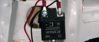
It so happened that my car has a G-222 generator installed (They were installed on cars before 1988, judging by the documentation and some websites).
The generator is working and there are no complaints about it, only the battery charge control lamp never came on. The fact is that the generator has pin 15, which is connected to the PC702 charging control relay, which switches the control lamps to the robot. Because of this, I really didn’t want to change the generator to a new one, especially since the old one completely copes with its work, and the light bulb is just the reason for incorrect switching. A light bulb for a car is very important; it can quickly determine whether a belt is broken or a generator is failing, so the question of its operation worried me very much. Once upon a time I already tried to restore a light bulb to a robot, but I didn’t have enough persistence, knowledge or good advice. I think many people will encounter this when they end up on a site that misled me. The site is quite well-known www.autoprospect.ru and I have found the information I need on it more than once, but this time I got caught. What's the matter you ask?! I’m telling you on the site they offer two connection diagrams with the 37.3701 generator and other modifications (We are not particularly interested) and a connection diagram for the G-222 generator, which is what I needed.
There was no reason not to trust the eminent site (as it turned out in vain). I called the wiring, took the relay, connected it according to the diagram, and it’s still there... The control light didn’t light up and still doesn’t light up. And I stopped. But then I decided to look for wiring diagrams on other cars and I found a wiring diagram for old and new-style generators on cars 2105-04.
At first glance, as in diagrams 2107, the only difference is in the warning lamp relay. Brown-white in the first case for the generator and in the second for the RS-702 relay. But let's take a closer look. In the diagram for switching on the new generator, the control lamp from the combined instrument goes with an orange wire back to the fuse block, as is the case with both diagrams for 2107. But in the second diagram it also comes white-brown, but it’s not brown that goes out from the lamp, but white-black the wire and it is very important that it goes to the ground. This is the whole nuance and error in the diagram for 2107 and the G-222 generator. I think the whole problem is that the one who drew the drawings for the site in electrical engineering saw two identical drawings at first glance, found the differences as it seemed to him only in the presence of the RS-702 relay, and everything else was a banal “Copy-Paste”, which then led to a headache. When you realize this, the error becomes visible to the naked eye. If you look again at the incorrect diagram given on the site, you can see that when the RS-702 relay is triggered, we get a ring (shown by the red line) and the light bulb in the circuit simply cannot light up since there is no circuit through it; it has the same +12 on both sides from the ignition on.
The correct diagram looks like this
You need to tear off the second wire from the lamp that goes to +12 when igniting and put it on the ground, which is what I did.
The wire on the dashboard does not go very well, after it the orange one is still fed to the indicator of insufficient brake fluid level and I had to cut the tracks.
and make jumpers
A small lyrical digression. Knowing now where I have +12 from the ignition on, I removed the snot from the instrument lighting that went to the yellow-blue wire of the button from the heater stove
and sealed the backlight directly into the tidy
I covered the places of my intervention with tsaponlak to prevent sin and oxidation.
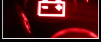
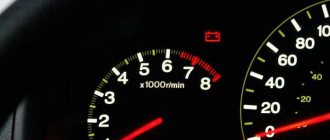
Well, the result is for the sake of what everything was started for, turn the ignition key and enjoy
the light is on as it should be, then we start the engine and it goes out for natural reasons