LADA VESTA. STEERING KNAKE AND HUB ASSEMBLY - REMOVAL AND INSTALLATION, DISASSEMBLY AND ASSEMBLY
Removal Place the car on a two-post lift, apply the parking brake and turn off the ignition (electrohydraulic lift type P-3.2G with a lifting capacity of 3.2 tons).
Loosen the front wheel mounting bolts (replaceable head 17, extension and wrench).
Remove the cap and unscrew the hub fastening nut (replaceable head 30, knob).
Raise the car to a height convenient for performing work.
Unscrew the fastening bolts and remove the wheel (replaceable head 17, extension and wrench).
Carefully, so as not to damage the dust cap, push the piston into the brake cylinder and spread the pads. When retracting the piston, monitor the brake fluid level and, if necessary, remove excess (flat-head screwdriver, hand pump, service container).
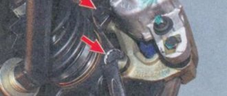
Figure 5-1 – Removing the front brake:
1 – steering fist;
2 – front brake mounting bolt;
3 – front brake
Unscrew the two bolts securing the front brake to the steering knuckle, remove and hang the front brake to the suspension spring (replaceable head 18, extension, wrench, technological hook). Attention. To prevent damage to the brake hose, it is not allowed to subject it to tensile or twisting loads, and the hose is not allowed to come into contact with sharp edges of the vehicle’s suspension parts.
Figure 5-2 – Removing the front brake disc: 1 – front brake disc; 2 – brake disc mounting bolt
Unscrew two bolts 2, Figure 5-2, fastenings and remove front brake disc 1 (Torx T40 angle wrench).
Figure 5-3 – Removing the protective casing: 1 – bolt securing the protective casing; 2 – protective casing
Unscrew the three bolts 1, Figure 5-3, fastenings and remove the protective casing 2 (angle key Torx T30).
Figure 5-4 – Disconnecting the front wheel speed sensor and steering linkage from the steering knuckle:
1 – front wheel speed sensor;
2 – speed sensor fastening bolt;
3 – steering knuckle;
4 – nut securing the ball pin of the tie rod end;
5 – outer tie rod end
Unscrew bolt 2, Figure 5-4, fastenings and remove front wheel speed sensor 1 from steering knuckle 3 (Torx T30 angle wrench). Remove harness 2, Figure 3-2, of the speed sensor wires from bracket 3 on the front suspension strut. Unscrew the nut 4, Figure 5-4, securing the steering rod ball pin 5 to the steering knuckle 3, holding the ball pin from turning if necessary, and disconnect the rod from the steering knuckle (hexagonal angled wrench 5, ring wrench 16, tie rod end puller). Unscrew nut 4, Figure 4-3, if necessary, holding the ball joint pin from turning, and remove the ball joint pin from the steering knuckle (ring wrench 18, angled Torx wrench T40, ball pin remover). Unscrew two nuts 4, Figure 3-2, bolts 6 securing the steering knuckle to the front suspension strut and remove the bolts. Remove the front wheel drive shaft from the hub and remove the steering knuckle and hub assembly. When removing the fist, fix the wheel drive in a suspended state (ring key 18, replaceable head 18, knob, hammer, firmware, technological hook).
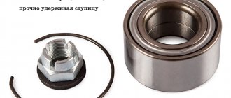
Replacing the front wheel hub bearing
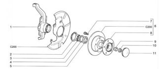
Figure 5-5 – Steering knuckle with hub assembly: 1 – front wheel hub; 2 – retaining ring; 3 – hub bearing; 4 – steering knuckle
Install the steering knuckle 1, Figure 5-6, on the press table, using technological supports under the surface of the knuckle, install mandrel 2 on hub 4 and press the hub out of the bearing (hydraulic press type KS-124 (Kochubeyevsky), mandrel marked “1” from set of mandrels 67.7853-9727).
Figure 5-6 – Pressing out the front wheel hub from the steering knuckle:
1 – steering fist;
2 – mandrel 67.7853-9727-1;
3 – retaining ring;
P – direction of pressing out the hub
Figure 5-7 – Pressing the inner ring of the front wheel hub bearing:
2 – inner ring of the bearing;
3 – stop 67.7853-9727-4;
4 – double-lever or three-lever puller
Place hub 1, Fig. 5-7, in a vice, install stop 3 on the hub and use puller 4 to compress the outer half 2 of the inner bearing ring remaining on the hub (vise with aluminum pads, double-lever or three-lever puller, stop marked “4” from set of mandrels 67.7853-9727).
Figure 5-8 – Pressing out the front wheel hub bearing from the steering knuckle: 1 – mandrel 67.7853-9727-2; 2 – bearings; 3 – steering knuckle; 4 – stop 67.7853-9727-5
Life hack: Vesta car front and rear wheel bearings - replacement instructions
In order for the wheel to rotate and stay firmly in place, in addition to the ball joint, the suspension mechanisms include a hub bearing. On Lada Vesta cars there are front and rear bearings, since in some Vestas there are drums at the back, not calipers. Replacing a part on a hundred will cost from 1000 to 2000 rubles. The wheel bearing tends to howl, the first Vesta cars were famous for this disease. As always, the first models come out like raw meat, often inheriting the diseases of previous models. Lada Vesta did not break this tradition. AvtoVAZ even gave an explanatory letter admitting that the front right/left wheel was howling and advised changing the assembly. Below in the article you will find the official letter. The price for the front wheel bearing of a Vesta car starts from 1000 rubles. The part is available for cars with and without abs. True, I have never seen Vesta without abs.
Adjusting the wheel bearing on a VAZ 2107
You can correctly tighten the front wheel bearing of a VAZ 2107 as follows:
If play and noise cannot be eliminated in this way, the bearing must be replaced.
The replacement procedure is quite simple. To replace the VAZ 2107 wheel bearing, you will need:
The work is carried out on a lift or after raising the front wheel with a jack.
- lift the car on a lift or “hang” the wheel using a jack;
- Unscrew the wheel mounting bolts;
- remove the wheel;
- unscrew the caliper mounting bolts;
- remove the brake caliper;
- pry up the protective cap of the hub with a screwdriver and remove it (sometimes you need to use a hammer for this);
- straighten the dented side of the hub nut, which prevents it from unscrewing spontaneously;
- unscrew and remove the washer nut;
- remove the hub from the car;
- pull out the bearing cage;
- remove the ring separating the outer and inner hub bearings;
- knock out the bearing races from the seat using an extension and a hammer;
- thoroughly clean the bearing installation area from old grease and dirt using rags and kerosene;
- press in the outer and inner bearing races
- thoroughly lubricate the internal separator;
- insert the internal separator;
- fill the inter-bearing space with lubricant by approximately 40%;
- insert the spacer ring;
- press in a new oil seal;
- install the hub on the axle;
- lubricate the external separator;
- insert external separator;
- install the external separator in place;
- put the washer in place and tighten the hub nut until it stops;
- achieve free rotation of the hub in the absence of play by smoothly unscrewing the nut;
- bend the side of the nut with a chisel or screwdriver, thereby preventing it from unscrewing;
- Reinstall the brake caliper and tighten the mounting nuts;
- install the protective cap;
- put the wheel in place and tighten the wheel bolts;
- lower the car.
Tips for replacing a wheel bearing
Timely elimination of play is a guarantee of long bearing service.
Welcome, friends, to the DIY car repair website. While driving your car, noise occurs in the front part of the suspension, a hum, sometimes even a whistle, this indicates that the VAZ 2107 wheel bearing most likely needs to be replaced.
In the front hub of the VAZ 2107 there is a pair of roller bearings, one internal, and the other, of course, external.
How to check a wheel bearing
- Jack up the car so that the wheel rotates freely.
- We place the stand under the threshold of the car.
- When the wheel rocks in different planes, a knocking noise occurs; it could be a bearing, a ball joint, or possibly a steering linkage, so let’s check further.
- We turn the wheel by hand; when noise appears, it will immediately become clear to you that the bearing needs to be replaced.
In the same way as described above, we check the other side of your vehicle, since most likely the hub bearings have worn out there too.
Basic faults
As a result of regular use of the car, over time, most parts wear out and may break. One of the most vulnerable parts of a vehicle is the suspension, which smooths out road unevenness and takes the blows.
The bearing design consists of two metal rings. Inside there are balls of insulating material. The entire structure is covered with plastic casings. Internal graphite-based lubricant protects materials from abrasion while the internal race of the part rotates along with the hub.
For no apparent reason, car parts usually do not break. The process occurs unnoticed, but allows the driver to have time to react to a breakdown if he pays attention to the characteristic signs in time.
The purpose of bearings is to ensure the rotation of the wheels and also to hold the hubs firmly. Let's look at their main malfunctions and possible causes:
- Front wheel play.
- Vibrations of different degrees of intensity.
- A pronounced hum and other extraneous sounds when the wheel rotates, similar to the grinding of metal, crunching, knocking.
- Vibration in the steering wheel that increases with speed.
- The car skids to the side.
- Off-road driving, extreme driving, with sharp braking, acceleration (drifting), can damage any, even reliable, part of the car.
- The cause of component failure may be vehicle overload.
- As a result of sand, moisture, or dirt getting into the rotating parts of the bearing, the lubricant may evaporate and the inner or outer rim may crack. During long-term operation, the protective elements of the part become unusable, the tightness of the structure is compromised, and dirt can penetrate into the working area, washing out the lubricant.
- The rollers themselves are rarely destroyed. The reason may be inadequate factory quality.
- If the mechanism is replaced incorrectly, another replacement will be required.
The technician will advise you, after detecting a malfunction, to go to the nearest workshop, not exceeding a speed of 40 km/h.
Structurally, the front and rear hubs of the Lada Vesta car consist of:
- metal frame: external, internal;
- a bearing with metal balls (rollers) located in it;
- insulating rings;
- special filler - graphite-based lubricant.
Before starting to disassemble the mechanism, it is necessary to diagnose the hub mechanism. To this end:
- Place the vehicle on a level platform with the parking brake released to check the front row.
- Install wheel chocks to check the rear row: jack up the front (or rear) part.
- We turn the car wheel and carry out troubleshooting.
- Use your hands to loosen the wheel up and down; there should be no play. If there is one, we dismantle it, replacing worn parts and components.
Installation
In order to cover the steering wheel of an X Ray or Vesta with leather braiding, no special knowledge or experience is required. The main thing is diligence and patience, since, despite the fact that the braid is pre-stitched and you only need to sheathe the steering wheel with it, you will have to set aside several hours for this.
Naturally, it is much more convenient to work when the steering wheel is removed, although some prefer to stretch the braid over the Vesta steering wheel right in the car. However, both experts and owners still recommend dismantling the steering wheel.
Replacing the front wheel bearing Lada Vesta - removal and installation
- Place the steering knuckle in a stationary vice and knock out the central part of the part.
- To dismantle the inner part of the cage, use a chisel, applying targeted blows with a hammer. Leave the outer part of the inner ring.
- Remove the mud ring from the hub.
- Using a chisel, move the inner race of the bearing.
- Use a puller to compress the part.
- Use pliers to remove the retaining ring.
- Remove the bearing. To do this, disconnect the inner race of the hinge; it is convenient to use round teeth.
- Remove the part along with the puller.
- Clean the surface from accumulated dirt, rust, and grease. Lubricate the inner surface of the steering knuckle.
- Clean out dents from the chisel, if any have formed.
- Apply a thin layer of graphite grease to the surface. Press in the new mechanism; the retaining ring should fit with the edge of the part.
- Press the new mechanism into the steering knuckle, applying force to the outer ring.
- Install a locking device on the groove of the steering knuckle socket.
- Attach the steering knuckle to the shock strut bracket, align, and tighten the nuts of the steering knuckle bolts.
- Insert the splined part of the outer drive joint into the wheel hub. Put on the washer and tighten the new fastening nut without tightening it.
- Attach the ball pin of the suspension arm to the steering knuckle and tighten the two bolts.
- Install the front brake guard and disc.
- Secure the front brake to the steering knuckle with two bolts.
Purpose of the VAZ 2107 wheel bearing
The VAZ 2107 wheel bearing is a part through which the wheel is attached to the steering knuckle, and the wheel itself rotates. In a car, this element is constantly affected by temperature changes, the environment, impacts from uneven road surfaces, jerks of the brakes and steering. If the bearing is in good condition, the wheel should rotate without any play, with noise and minimal friction allowed.
The part in question has a fairly large resource. However, there are many factors that sharply reduce its service life. These include:
- Poor quality of roads is one of the reasons for the rapid failure of wheel bearings. This is explained by the fact that the element is located in the center of the wheel and absorbs strong loads during an impact when hitting bumps. For some time, the bearing withstands such impacts, but gradually collapses.
- Exposure to an aggressive environment. In summer, moisture and road dust get inside the hub, and in winter, chemical reagents penetrate.
- Overheat. Wheel rotation is constantly associated with friction and increased temperature. With constant heating and cooling, which is especially typical in winter, the service life of bearings is reduced.
Where is the wheel bearing installed?
Based on the name, you can already understand that the part is located near the hub. On the VAZ 2107, the element is installed in its internal cavity and changes, as a rule, when it fails, as evidenced by characteristic signs.
How to replace the rear wheel bearing of Lada Vesta
Place the car on a lift and turn off the ignition
Remove the cap 2, Figure 1, rear wheel hubs.
Checking the axial clearance of the wheel bearing
The axial play in the rear wheel hub bearing should not exceed the permissible value of 0.03 mm. If the axial clearance exceeds the permissible value, the bearing must be replaced.
We install an indicator on the brake drum, rest the indicator leg against the end of the hub axis and check the axial clearance of the rear wheel hub bearing by applying an alternating load to the drum along the hub axis.
If the axial play in the bearing exceeds the permissible value of 0.03 mm, the bearing must be replaced.
Using a 30mm socket, unscrew nut 2, Figure 2, securing the hub and remove brake drum 1.
Using a three-lever puller, we press magnetic ring 1 from brake drum 2, Figure 3.
Remove the locking ring 4.
We install brake drum 2, Figure 4, on the press table, install mandrel 1 on the bearing and press out bearing 3 of the rear wheel hub from the brake drum.
Clean, rinse and blow out the steering knuckle and hub with compressed air. Clean the grooves for the retaining rings.
Place brake drum 3, Figure 5, on the press table on a technological stand under the surface indicated in the figure.
Install hub bearing 2 into the brake drum, install mandrel 1 onto the bearing and press the bearing until it stops.
Apply the pressing force to the outer ring of the bearing.
Secure the bearing in the brake drum with retaining ring 4, Figure 3.
Place brake drum 3, Figure 6, on the press table with emphasis on the surface indicated in the figure.
Install magnetic ring 2 on the brake drum, install mandrel 1 on the ring and press the magnetic ring until it stops.
The hub nuts must be replaced; reuse of the nuts is not permitted.
Install the brake drum onto the rear wheel hub axle and tighten the new fastening nut. The tightening torque of the nut is 158 - 192 Nm (15.8 - 19.2 kgf.m).
Press cap 2, Figure 1, of the rear wheel hub into the brake drum.
Check the operation and, if necessary, adjust the parking brake drive.
Press the brake pedal 2-3 times, check and, if necessary, bring the brake fluid level in the brake hydraulic reservoir to normal.
Check the effectiveness of the service brake system.
Source
Tightening torques for critical threaded connections
Note: The tightening torques for engine parts are given in more detail here
| Detail | Tightening torque, Nm |
| Engine | |
| Cylinder head bolt | see here |
| Nut and bolt securing the intake pipe | 2,1-2,5 |
| Collector fastening nut | 21-25 |
| Additional muffler clamp nut | 14-16 |
| Automatic camshaft belt tensioner bolt | 30-36 |
| Bolt securing the bracket for auxiliary units M8/M10 | 15-24/33-52 |
| Accessory belt tensioner nut | 30-36 |
| Camshaft bearing housing bolt | 8-10 |
| Camshaft pulley bolt | 70-83 |
| Thermostat housing mounting nut | 16-22 |
| Oil sump bolt | 5-8 |
| Flywheel bolt | 75-85 |
| Water pump mounting bolt | 7-8 |
| Crankshaft pulley bolt | 95-115 |
| Muffler exhaust pipe fastening nut | 21-25 |
| Oil pump mounting bolt | 9-10 |
| Cylinder head cover bolt | 7-9 |
| Oxygen concentration sensor | 40-60 |
| Oil pressure warning sensor | 35 |
| Knock sensor mounting bolt | 11-24 |
| Crankshaft position sensor mounting bolt | 8-12 |
| Throttle assembly nut | 5-8 |
| Fuel rail mounting bolt | 9-14 |
| Clutch | |
| Bolt securing the basket to the flywheel | 20-31 |
| Bolt securing the slave cylinder to the clutch housing | 18-24 |
| Transmission | |
| Bolt securing the gearbox (clutch housing) to the engine | 60-80 |
| Drain plug | 29-46 |
| Filler plug | 29-46 |
| Nut securing the rocker to the body base | 14-20 |
| Front suspension | |
| Bolt securing the subframe to the body | 94-126 |
| Bolt securing the upper support of the shock absorber strut to the body | 18-24 |
| Bolt securing the shock absorber strut to the steering knuckle | 90-120 |
| Bolt securing the rear suspension arm hinge to the subframe | 94-126 |
| Bolt securing the front suspension arm hinge to the subframe | 94-126 |
| Rear subframe extension bolt | 7-9 |
| Front subframe extension bolt | 38-50 |
| Stabilizer link pin fastening nut | 53-71 |
| Bolt securing the stabilizer bar to the cross member | 18-24 |
| Nut securing the shock absorber rod to the upper support | 53-71 |
| Nut securing the ball joint to the steering knuckle | 53-71 |
| Wheel bearing nut | 238-322 |
| Wheel bolt (additional info) | 90-120 |
| Rear suspension | |
| Shock absorber lower mounting bolt | 90-120 |
| Rear suspension arm mounting nut | 106-143 |
| Suspension arm bracket mounting bolt | 90-120 |
| Upper support nut | 53-71 |
| Shock absorber rod mounting nut | 30-40 |
| Trunnion bolt | 90-120 |
| Wheel bearing nut | 158-192 |
| Wheel bolt (additional info) | 90-120 |
| Steering | |
| Bolt securing the steering gear to the subframe | 153-207 |
| Steering column mounting nuts | 18-24 |
| Steering column intermediate shaft terminal connection bolt | 53-71 |
| Steering wheel bolt | 38-50 |
| Tie rod end locknut | 15-21 |
| Rod end ball pin fastening nut | 32-42 |
| Attaching the drive rod joint to the rack | See here |
| Brake system | |
| Vacuum booster mounting nut | 18-24 |
| Brake disc bolt | 12-16 |
| Bolt securing the shoe guide to the steering knuckle | 90-120 |
| Guide pin bolt | 26-31 |
| Brake shield mounting bolt | 7-9 |
| Rear brake cylinder mounting bolt | 7-11 |
| Brake pipe fitting nut | 14-20 |
| ABS hydroelectronic module bracket mounting nut | 18-24 |
| Electrical equipment | |
| Nut securing the terminal to the battery | 4-6 |
| Headlight mounting bolt | 3-5 |
| Rear light fastening nut | 2-3 |
| Generator mounting bolt | 21-27 |
| Nut securing the power wire terminal to the generator | 10-13 |
| Starter mounting bolt | 18-24 |
| Nut securing the power wire terminal to the starter | 10-13 |
Note. For other threaded connections, the tightening torques are as follows: M6 - 10 Nm; M8 - 25 Nm; M10- 50 Nm; M12 - 105 Nm; M14 - 180 Nm.
Video
Source
Sequencing
The procedure for removing the hub support bearing is as follows.
- Drive the car into the garage and loosen the bolts holding the wheel. It is important to just loosen the bolts - you do not need to unscrew them completely. Next you will need to remove the terminals from the battery.
- Raise the car with a jack and place it on trestles. If possible, it is recommended to use a lift. This will make the operation more comfortable.
- Remove the wheel from the car. Next, using a soft brush, you should clean all surfaces from dirt, plaque and dust. The further procedure must be carried out with utmost cleanliness. It would also be a good idea to place cardboard or a rag under the work area.
- Next, you need to open the cap of the hub nut and use a 30 socket to unscrew it. In this case, you should use a lever - the device is clamped tightly enough and secured, which prevents it from unintentionally unscrewing.
- When you have access to the caliper, you need to use a flat-head screwdriver to move the piston and spread the pads. During the procedure, you need to monitor the level of brake fluid in the Republic of Belarus. If the liquid overflows, it is convenient to remove the excess with a syringe.
- The next step is dismantling the caliper. Using wrench No. 18, unscrew the two mounting screws and hang the brake on a spring or other element. In this case, you will need to be careful and remove the brake line away from sharp objects.
Next, the brake disc is unscrewed. To do this, take a TORX head of the appropriate size and unscrew the two fastening screws. The disc itself must be carefully placed on a clean surface. During removal, it is recommended to touch the working surface of the rotor less - this part is sensitive to grease. Next, using the same torx, you will need to unscrew the protective covers and speed sensor. For convenience, the sensor can also be attached to a spring.
- Next, you should rip off the tie rod mounting nut and, using a squeezer, remove it from the steering knuckle. For convenience, you can hold the ball part from turning with a hexagon.
- After preparation, you need to dismantle the suspension arms and wheel drive. Here the mounting bolts and nuts are unscrewed in order. The master’s task is to completely free the steering knuckle and hub from the suspension elements.
- After all the manipulations, you can begin to replace the bearing itself. The fist is clamped in a yew or fixed in another convenient way.
- Next, using a special puller, you need to remove the retaining rings from the seats. In this case, you need to act carefully - the rings are made of special steel and can bounce off. Then, using a tool, you need to knock out the hub along with the bearing from the steering knuckle. The main rule here is accuracy. You need to hit the guide carefully so as not to damage the part.
- Now the hub is completely freed from the knuckle and the bearing can be pulled off.
- Subsequent steps require a special squeeze. If there is no such thing available, you should not even start the procedure. The principle of operation is shown in the photo.
- Next, replacing the support bearing of the Lada Vesta proceeds to the vehicle assembly stage.
- Using a stream of compressed air, you need to clean the seats and completely remove all dirt from the parts.
- Install the outer retaining ring onto the steering knuckle and press the new bearing all the way into its seat. Insert the second ring into the retaining groove.
- The final stage is pressing the hub into the inner part of the bearing.
- Subsequent assembly of the mechanism is carried out in reverse order. The most important factor is maintaining utmost cleanliness and precision. Even a small amount of dirt that gets into the inside during installation significantly shortens the life of the parts.
Possible causes of increased wear
Drum wear is inextricably linked with pad wear. Moreover, the dependence can be both direct and inverse.
Reducing the life of drums is facilitated by:
- The quality of the pads and the brake disc itself.
- Technical characteristics of the pads. The lining can be of high quality, but at the same time “soft”. It brakes smoothly, but wears out faster than the “hard” one. But it protects the surface of the drum. A “hard” pad is more aggressive towards the brake drum, so the mileage of the latter is shorter.
- Frequent use of brakes is driving in city conditions, with many traffic lights and crossings.
- Aggressive driving. Constant sharp braking, overheating of mechanisms.
- Off-road driving. The terrain is constantly changing, and every now and then you have to slow down. At the same time, dust and sand do not spare the working surfaces of mating pairs (pads, drums).
- Untimely maintenance, delayed repairs. If you can hear the sound of the steel base of the pad touching the disc, it means the wear has long been beyond the limit. You shouldn’t convince yourself that it’s not scratching too much yet. We urgently need to repair the system while there is a chance to get away with replacing the pads. In winter, when approaching your house, you can drive through a puddle and leave the car overnight. The block will freeze to the drum. When starting, the lining slightly detaches from the block, and after a while it completely falls off. For the reasons described above, the drum wears out intensively.
- A handbrake that gets stuck when tightened can cause increased friction, resulting in wear, overheating, and warping of parts.
How to replace the rear bearing on Vesta
The standard replacement of the Lada Vesta rear wheel bearing is carried out independently only after measuring the axial clearance and checking the condition of the part. If the troubleshooting results are not satisfactory, the bearing needs to be replaced. The operation will require similar instruments. And the procedure itself looks like this.
- The preparatory work is similar to the procedure for replacing the front wheel.
- The disc is removed from the car and the brake drum is exposed.
- Using wrench No. 17, the hub cap is removed and the brake drum is dismantled.
When using a magnetic puller, the magnetic ring is squeezed out. The part helps hold the structure in place. After disassembling the mechanism, the TB should be installed on a flat surface and an extension should be installed in the inner part of the bearing to press it out. For the best effect, you will need a press; if you don’t have one, you can use a hammer.
Replacing the axle bearing
The axle shaft is an integral part of the rear axle of the VAZ 2107. The axle shaft itself practically does not break, but the bearing by which it is attached to the axle housing sometimes fails. Its purpose is to rotate the axle shaft smoothly and evenly while the car is moving. Signs of bearing failure are the same as those of the hub elements. If problems occur, it is necessary to dismantle the axle shaft and replace the faulty part.
Bearing removal
Before starting work, you need to prepare the following list of tools:
- set of socket wrenches with a crank;
- hammer;
- flat screwdriver;
- chisel;
- grinder;
- new axle bearing with retaining ring.
To replace, follow these steps:
- Raise the rear wheel using a jack, then remove it, not forgetting to install stops under the front wheels.
- Remove the brake drum.
Installing a new part
After removing the bearing, you can immediately begin reassembly:
- Clean the axle shaft from dirt and wipe it with a rag.
- Press the new bearing onto the axle shaft, and then install the retaining ring. To install the latter, it is advisable to heat it up with a blowtorch, which will ensure easier installation and reliable retention after cooling.
Video: replacing the axle bearing on a “classic”
Replacing a wheel bearing on a VAZ Seven is not a complicated procedure. To carry it out, you will need to prepare the necessary tools and materials, as well as read the step-by-step instructions. If you choose a quality product and carry out repair work correctly, the bearing will work for a long time without any problems.
Generator repair
The following describes the repair procedure for sliding inserts and power generation devices. Replacing the Lada Vesta generator bearing will require the tools indicated at the beginning of the article. The repair procedure itself looks completely different.
- Place the machine on a level surface and securely fix it.
- Disconnect battery power.
- Loosen the tension roller of the crankshaft belt and accessories.
- Using a Phillips screwdriver, unscrew the power conductors of the generator device and remove them from the repair area.
- The generator is removed using a 13 mm wrench and a screwdriver. To do this, you need to find and unscrew the two bolts on the bracket securing the device to the engine block.
- Next, you can carefully remove the device itself from the machine for subsequent repairs.
- After dismantling, use a screwdriver to unscrew the two screws of the cover and remove the latter.
- Under the cladding there is a diode bridge and a regulator. The parts are fixed on a special panel, which is pulled off the shaft along with the bearing.
Loose wheel bolts
For various reasons, personal carelessness, including insufficient tightening of bolts, contributes to the appearance of extraneous sound. If you detect an uncharacteristic sound, check the tightening of the bolts yourself. If you do not have a wheel wrench, contact a service station for help.
After tightening, be sure to check that the wheel does not knock and make sure that the cause has been eliminated.
We do not recommend doing your own repairs while the machine is under warranty. Otherwise, it may be classified as a breach of contract by the consumer. It is not uncommon for a factory warranty to be voided prematurely.