As you know, additional equipment is often installed on a car, which draws additional voltage from the on-board network. Thus, the voltage indicator on a VAZ-2114 can drop to a critical level of 11 volts . If you also install additional air conditioning or heated seats, this may result in the starter not having enough power to start the engine. How to fix the problem? Make sure that the voltage in the on-board network increases.
Video about increasing the voltage in the on-board network on VAZ cars:
The video will tell you how to increase the voltage of the generator and on-board network with your own hands, and will also tell you about some of the nuances and subtleties of the process
Method number 1. Minimizing losses
On the path of electric current from the generator to consumers, the greatest losses occur in places of poor contacts. We are talking about the terminals and spots with which the wires are connected. If in such places the contact has deteriorated due to oxide or other dirt, this means that the cross-section here has decreased. And as the cross-section of the conductor decreases, its electrical resistance increases in direct proportion.
Through such contacts, the current flows “worse”; accordingly, the voltage also drops (Ohm’s law works for a section of the circuit). If, for example, on the way from the generator to the battery, all connecting contacts are in poor condition, then low voltage in the on-board network is guaranteed.
In addition to where the conductors connect to automotive equipment, you should also be aware of the conductors themselves. They must have a cross-section sufficient for their section of the chain. Otherwise, there will also be losses on the wires, which, according to the Joule-Lenz law, will be spent on heating them.
How to reduce wire resistance? This is affected by their length and cross-section. We will not consider the material, since today all the wires are copper. If the car's wiring has been repaired and replaced, it is necessary to check whether there are any uselessly long wires that can easily be shortened. As for the cross-section, it is not always possible to judge it by its thickness. And that's why.
The fact is that the wires of the car on-board network are made multi-core. Each of them consists of many thin veins twisted into one conductor. This is done so that the wire has a larger cross-section and, at the same time, remains flexible. During long-term operation, copper strands can break, which is why the cross-section decreases, and the resistance with losses in this area increases. Most often, fractures can be seen at the ends of the conductors, where the protective insulation has been removed from them (in front of the terminals).
As practice shows, all the factors described in this subsection together are capable of reducing the on-board voltage by up to 1 volt. Accordingly, if shortcomings of this kind are eliminated, then on the voltmeter, instead of a sluggish 13.2 V, you can see the optimal 14.2 V. Such an increase will be observed if the case is completely advanced. And so, you can count on an increase in the voltage of the on-board network by several fractions of a volt (which is often not enough).
However, that's not all. In addition to the reduction in voltage, due to the problems described, it drops significantly under heavy loads. For example, when everything is turned off, the voltmeter shows 14.2 V (order). And after turning on the lights, headlights, stove and music, the readings drop to 13 V. So, quite often, after minimizing losses, such a drawdown was reduced by half, or even three.
Pulse type inverting converter
A pulse-type inverting converter contains the same combination of basic elements, but again in a different connection (Fig. 3): a series chain of switching element S1, diode VD1 and load resistance RH with filter capacitor C1 is connected to the power source.
Inductive energy storage L1 is connected between the connection point of the switching element S1 with the diode VD1 and the common bus.
Rice. 3. Pulse voltage conversion with inversion.
The converter works like this: when the key is closed, energy is stored in an inductive storage device. Diode VD1 is closed and does not pass current from the power source to the load. When the switch is turned off, the self-inductive emf of the energy storage device is applied to a rectifier containing diode VD1, load resistance Rн and filter capacitor C1.
Since the rectifier diode passes only negative voltage pulses into the load, a voltage of a negative sign is formed at the output of the device (inverse, opposite in sign to the supply voltage).
A little theory
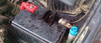
First you need to understand what functions the battery performs:
- Starts the engine. Namely, it provides energy (spark) for ignition and rotates the starter motor. Well, and, of course, in modern car models it provides power to all electronics. If the battery is completely discharged or absent, the engine cannot be started at all;
- When the engine is not running, it powers all electronics (dimensions, electrical equipment, etc.);
- Performs auxiliary functions for the generator when the load on it is too heavy.
As you can see, the role of this part in the design of any machine is very significant. For this reason, the battery must not only be charged in a timely manner (especially for those who travel short distances), but also its performance must be regularly checked. In this case, it will be able to last much longer, and the driver will be able to avoid many problems on the road.
How to increase the generator charge using an additional diode
Many motorists have encountered the concept of low voltage in the network. The culprit of the situation was the generator, which produced an insufficient amount of current. Is there any way to increase the voltage produced by the unit? How to increase the power of the generator without damaging the circuit and the overall system.
Diode in the circuit
1 Diode in the circuit 2 About regulators
Installing a diode with a toggle switch is the easiest way to increase the voltage. There is no need to bother, look for a lot of information in books, etc. Everything is as accessible as possible, no special difficulties.
This option of increasing the voltage, despite its simplicity, gives the most reliable result. Ideally suited for domestic and VAZ car models.
The purpose of this method of increasing the voltage in the vehicle's on-board network is to deceive the regulator, which is located inside the generator. As you know, on old domestic car models (kopek, VAZ 2105, etc.) the voltage drop sometimes reaches critical values - sometimes it drops to 12.5 volts. The battery, of course, will not be charged at this voltage.
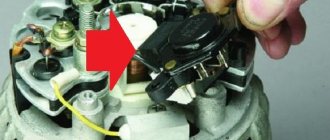
A voltage regulator is the same brushes, a tablet, a chocolate bar - there are many names, but it is the same element that is responsible for regulating the voltage in the generator. On our domestic cars, mostly older ones, the tablets are of poor quality. They do not regulate voltage well, and as mentioned above, sometimes the current value drops below the baseboard.
So, what you need to do is insert an additional diode into the circuit. By this we will achieve the following: by how much the voltage on the diode is reduced, the regulator will increase the total current in the circuit.
There are several ways to integrate a diode. One of the best - remotely. Take a simple toggle switch and install it somewhere convenient.
Obviously, the toggle switch should be routed through the wire to the generator. You can insert the diode into the slot in the generator bridge, in the place where the wiring runs from the excitation winding to the regulator. That is, we simply insert the diode into the wiring between the bridge and the regulator.
We connect a separate toggle switch to the diode through two wires, as shown in the photo below.
When the voltage in the on-board network is sufficient, for example, in the summer, the diode is simply installed and not used. If the current is low, just turn on the toggle switch by activating the diode. In this way, we deceive the regulator.
The following diodes can be used.
Their analogues, for example, imported ones, are also suitable. They are much more compact, made of plastic (body). Domestic - metal.
Using a diode, you can provide a voltage drop of 0.9 or 1.2 volts. Thus, if the drawdown reaches 13-13.6, then approximately 1 volt will be added by the regulator. This is normal for winter loads. The standard drawdown of the regulator should be up to 13.8 volts, not lower. At this value, the battery can still charge, but if the voltage is lower, it won’t.
A drop in voltage below standard values for modern calcium batteries is especially critical. The fact is that low drawdown kills such batteries; they deteriorate. Naturally, an increased voltage indicator is not recommended. It should be no more than 14.6 volts (more about this in the table at the end of the article).
Installing a diode in a circuit is a universal solution that gives good results. However, there are some important points to keep in mind:
- Observe polarity when connecting an additional diode. If you break this rule, the battery will not be charged.
- The diode must be selected so as to deliver a current of at least 5 A.
- It is advisable to install the diode outside the generator, as it will get very hot.
- Silicon diodes are considered more efficient. They are capable of taking voltage within 0.8-1.2. But germanium diodes are no more than 0.7 volts.
About regulators
Structurally, tablets that control the voltage in the generator are capable of increasing the current to 13.6 volts. It is known that there are two schemes for connecting the regulator: old and new.
The old circuit is a more reliable option, which does not increase the voltage too much, but also does not allow it to drop to critical values. But the new one - although it is completely copied from the old one, has many shortcomings.
Chronic undercharging of the battery is precisely the drawback of the new scheme. Starting the engine becomes problematic in the cold season. Owners have to install preheaters or come up with something else.
Poor quality regulators force the battery to absorb energy only in the summer, i.e., at above-zero temperatures. In winter, especially if you make short trips by car, the battery does not have time to warm up, at least to 0, and periodically discharges.
conclusions
Increasing the voltage of the VAZ-2114 generator with your own hands is real and quite simple. At the same time, the cost amounted to 500 rubles . It is worth noting separately that if you do not have the necessary skills or abilities to work with automotive electronics, then you should contact a car service center, where everything will be done quickly and efficiently, and of course, at the expense of the car enthusiast.
Many motorists have encountered the concept of low voltage in the network. The culprit of the situation was the generator, which produced an insufficient amount of current. Is there any way to increase the voltage produced by the unit? How to increase the power of the generator without damaging the circuit and the overall system.
Why does the voltage drop?
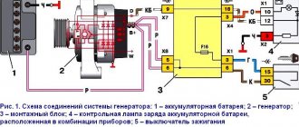
What should be the normal voltage in the on-board network? The voltage in the vehicle's 12 V on-board network should be 14.2-14.4 Volts. This applies to all vehicles, from Zaporozhets to Gelendvagens. This parameter should be present when the engine is running under load.
If there is a voltage drop caused by insufficient battery charge at 12 volts, then when you turn on, for example, optics, this parameter will be below 14 volts. This is because the excitation winding of the generator device is powered by the battery through feedback. And if the battery is not fully charged, the network will not be able to ensure optimal winding current and normal operation of the generator device.
This manifests itself when outdoor lighting is activated and is accompanied by a general loss of electrical circuit power. The lighting may be dim when idling, but when the driver accelerates, the light will stabilize to normal. Therefore, battery diagnostics should be carried out not by voltage when starting the engine, but by the electrolyte density parameter. This will prevent a difference in readings between the electromotive force of the battery and its current.
Note that the voltage of the vehicle’s on-board network may vary depending on the climatic conditions of the region in which the vehicle is operated. If the car was driven from the south, and you live in the north, then a slight drop in this indicator in the car’s electrical circuit is allowed. If a vehicle is using a partially discharged battery, it must be charged, otherwise the entire charge will quickly decrease and the battery will be inoperable.
To know how to increase the voltage in the electrical circuit of a car, you need to understand the reasons:
- Battery malfunction - as practice shows, this is one of the common causes. In order for the battery to replenish its charge after parking, you need to drive the car for about 20 minutes. But if the battery is discharged for certain reasons (for example, due to sulfation of the plates or due to a lack of electrolyte), then this method of replenishing the charge will not help. It is necessary to accurately identify the reason why the battery does not hold a charge and eliminate it - replenish the electrolyte level, and sometimes simply charge it. If you realize that the battery cannot be restored, then it is better to replace it.
- Generator. Incorrect operation of the generator can lead to problems with the on-board network. Before increasing the voltage in the wiring, you need to identify the cause of the malfunction of the generator unit.
- Leakage current. Sometimes it happens that a break in the electrical circuit leads to a current leak. To eliminate the problem, it is necessary to identify the exact location of the leak and eliminate the break.
- Using equipment that is not suitable. If the rating of the electrical appliances used does not match the one set by the manufacturer, this will lead to a voltage drop. If you use powerful lighting lamps or many different gadgets for which the battery is not designed, this will cause a voltage drop. The battery will provide the charge necessary for the normal operation of light bulbs or electronic devices, but it will not have time to be replenished.
Diode in the circuit
ATTENTION! A completely simple way to reduce fuel consumption has been found! Don't believe me? An auto mechanic with 15 years of experience also didn’t believe it until he tried it. And now he saves 35,000 rubles a year on gasoline! Read more" Installing a diode with a toggle switch is the easiest way to increase the voltage
There is no need to bother, look for a lot of information in books, etc. Everything is as accessible as possible, no special difficulties.
This option of increasing the voltage, despite its simplicity, gives the most reliable result. Ideally suited for domestic and VAZ car models.
The purpose of this method of increasing the voltage in the vehicle's on-board network is to deceive the regulator, which is located inside the generator. As you know, on old domestic car models (kopek, VAZ 2105, etc.
) the voltage drop sometimes reaches critical values - sometimes it drops to 12.5 volts. The battery, of course, will not be charged at this voltage.
A voltage regulator is the same brushes, a tablet, a chocolate bar - there are many names, but it is the same element that is responsible for regulating the voltage in the generator. On our domestic cars, mostly older ones, the tablets are of poor quality. They do not regulate voltage well, and as mentioned above, sometimes the current value drops below the baseboard.
So, what you need to do is insert an additional diode into the circuit. By this we will achieve the following: by how much the voltage on the diode is reduced, the regulator will increase the total current in the circuit.
There are several ways to integrate a diode. One of the best - remotely. Take a simple toggle switch and install it somewhere convenient.
Obviously, the toggle switch should be routed through the wire to the generator. You can insert the diode into the slot in the generator bridge, in the place where the wiring runs from the excitation winding to the regulator. T.
That is, we simply insert the diode into the wiring between the bridge and the regulator. We connect a separate toggle switch to the diode through two wires, as shown in the photo below.
When the voltage in the on-board network is sufficient, for example, in the summer, the diode is simply installed and not used. If the current is low, just turn on the toggle switch by activating the diode. In this way, we deceive the regulator. The following diodes can be used.
Their analogues, for example, imported ones, are also suitable. They are much more compact, made of plastic (body). Domestic - metal.
Using a diode, you can provide a voltage drop of 0.9 or 1.2 volts.
Thus, if the drawdown reaches 13-13. 6, then approximately 1 volt will be added by the regulator. This is normal for winter loads.
The standard drawdown of the regulator should be up to 13.8 volts, not lower. At this value, the battery can still charge, but if the voltage is lower, it won’t.
A drop in voltage below standard values for modern calcium batteries is especially critical. The fact is that low drawdown kills such batteries; they deteriorate. Naturally, an increased voltage indicator is not recommended.
It should be no more than 14.6 volts (more about this in the table at the end of the article).
Installing a diode in a circuit is a universal solution that gives good results. However, there are some important points to keep in mind:
- Observe polarity when connecting an additional diode. If you break this rule, the battery will not be charged.
- The diode must be selected so as to deliver a current of at least 5 A.
- It is advisable to install the diode outside the generator, as it will get very hot.
- Silicon diodes are considered more efficient. They are capable of taking voltage within 0.8-1.2. But germanium diodes are no more than 0.7 volts.
What voltage on a car battery is generally considered normal?
This also refers to the voltage of a charged car battery without load. This is 12.5–13.2 V. The final voltage is obtained at the end of recharging. What voltage should a charged car battery show after 12 hours with the engine off? This is 12.6–12.8 V. To get accurate data, measurements are taken about 12 hours after the engine stops running. This could be, for example, in the morning when the car spent the night parked or in a garage. Before measuring, remove one terminal (“ground”) from the battery. A new and charged battery with a capacity of, for example, 50 A/h can hold its charge unchanged for 141 days (at positive air temperatures) if it is disconnected from the vehicle’s on-board power supply. When connected to it, the charge retention time is reduced by 2 times. Why? Even when the power unit is turned off and the ignition is turned off, current consumption continues: for example, due to the connected alarm system, the leakage ranges from 0.02 to 0.05 A/h.
Minimum voltage
To avoid deep battery discharge, which is fraught with irreversible chemical processes (sulfation), and battery failure, it is necessary to constantly monitor the voltage. The minimum voltage of the car battery is 10.5 V (use the charger to restore the functionality of the product). U = 9 V is a different matter. With this value, the product can only be charged normally with a high-quality charger. But even a reconditioned battery is unlikely to work fully. There are, of course, special schemes for desulfating the battery, but, it is worth repeating, this will not give a 100% effect. This situation may indicate a possible short circuit between the plates.
Under load
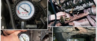
Measuring the voltage at the battery terminals under load involves using a special device - a load fork. But do not forget: the device only determines the overall performance of the battery and the degree of its charge or, conversely, discharge. This device will not determine the battery capacity and the beginning of sulfation (if it occurs, of course). Based on this, it is obvious that the device readings do not allow us to draw a conclusion about the service life of the battery. The device consists of:
- from a case with a multimeter;
- a spiral that performs the function of resistance;
- wires ending in alligator clips;
- switch
There are two types of devices: analog (with an arrow) and digital. The latter are more popular as they give more accurate readings. Almost all plugs are designed to operate at positive temperatures from +1 to +35 degrees. But there are also expensive models that can function properly even in thirty-degree frost. The current generated by the device ranges from 100–200 A. In some models, this value can be adjusted. The battery test time under load is no more than 10 seconds. Interestingly, according to EU standards it reaches 20 seconds. The normal voltage of a car battery without load is 12.6–12.7 V.
Engine running
When the engine is running, the voltage on the car battery will be slightly higher due to the generator - 13.6–14.2 V. Disclaimer: within ten minutes after starting it is higher. Checking the voltage on the car battery with the engine running should be done after the engine has been running for at least 15 minutes. Next, turn on all energy consumers in the car:
- windscreen wipers;
- rear window defroster;
- heater (at maximum mode);
- high beam;
- radio
The voltmeter readings should change slightly - by 0.2–0.3 V. If the car battery voltage drops by a greater value while the engine is running, problems with the generator may occur. It makes sense to make a small digression here. In some cars (for example, VAZ2108–2115) a standard native generator is installed on the conveyor belt, producing 80 A. If you use consumers, and many still use such things as a subwoofer, an amplifier for the radio (especially if the volume is turned up to full power), then the generator It simply cannot cope with the load, and the voltage on the battery becomes less than normal. There is only one way to solve the problem: purchase a 100 A generator (it fits the mounts).
Diagnostics of the relay regulator
Checking the relay regulator when recharging the battery is not a complicated procedure and you can do it yourself using a multimeter.
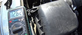
The test comes down to measuring the voltage at the battery terminals under different operating modes of the power plant. That is, we simply connect the multimeter probes to the terminals and measure the voltage first at XX, then at medium speeds, and then at high speeds.
At idle, the normal voltage is 13.2-14.0 V, at medium speeds - 13.6-14.2 V, at high speeds - up to 14.5 V.
If the values exceed the specified values, you should check and clean the contacts of the charging system circuit and repeat the procedure again.
If cleaning does not help, we check the relay separately (removed from the car), but for this you will need a power source with regulated voltage (you can use a battery charger), as well as a regular 12 V lamp.
The essence of the test is this: we connect the negative wire from the charger to the housing, and connect the positive wire to the regulator terminal. The lamp is connected to graphite brushes (polarity is not important).
When checking, we first set the voltage at the source to 12.7 V, at which the lamp should light up. We gradually increase the value to 14.5 V. When the specified value is reached, a working regulator should operate and the lamp will go out.
If it continues to light when exceeding 14.5 V, then the unit is faulty and requires replacement.
Stable voltage is the key to uninterrupted operation of automotive electrics. The regulator assembly is responsible for its alignment. This is an inexpensive and reliable part, but sometimes it breaks down and the current begins to drop low, jump or disappear. In this case, the unit is diagnosed and replaced. It is important to conduct differential diagnostics to separate relay problems from problems with wiring, the battery, or the generator itself.
There are methods for increasing voltage, but they must be used carefully and with an understanding of the possible consequences.
How, in theory, can you increase the voltage in the on-board network?
To answer this question, you need to know something about this very on-board network. How does it work, what does the voltage in it depend on? To find out, there is no need to study the entire on-board network. It is enough to consider the node that is responsible for generating electricity and stabilizing it.
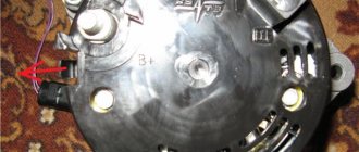
In simple words, this is how it works. In order for a generator to generate electricity, an electromagnetic field is forcibly created in it. The strength of this field determines the output voltage (which goes to the battery and consumers). The electromagnetic field is created in the generator rotor, to which a constant voltage is supplied through the brush assembly. The strength of the electromagnetic field and, accordingly, the voltage of the on-board network depend on the magnitude of this voltage.
That is, in order for the network to have the required voltage, control voltage must be supplied to the brush assembly of the generator. The voltage regulator relay is responsible for this. In its simplest form, it is a device that “monitors” what the generator outputs and “decides” what control voltage to apply to excite the electromagnetic field. As a result, it turns out that no matter how fast the generator rotates, it always outputs the same voltage to the network.
Accordingly, in order to increase the voltage of the on-board network, it is necessary for the voltage regulator to supply a higher voltage to the brush assembly of the generator. This can be done in several ways, which are described below.
It is worth adding here that the on-board voltage depends not only on the generator and the relay regulator. After all, in addition to the fact that electricity must be generated, it must also be delivered to consumers, which include batteries. Accordingly, if there are losses along the delivery route, then not all generated voltage will reach consumers. Therefore, increasing the on-board voltage should start with this.
Pulse converters and stabilizers
To stabilize the output voltage of pulse stabilizers of any type, conventional “linear” stabilizers can be used, but they have low efficiency. In this regard, it is much more logical to use pulse voltage stabilizers to stabilize the output voltage of pulse converters, especially since such stabilization is not at all difficult.
Switching voltage stabilizers, in turn, are divided into stabilizers with pulse-width modulation and stabilizers with pulse-frequency modulation. In the first of them, the duration of control pulses changes while their repetition rate remains unchanged. Secondly, on the contrary, the frequency of control pulses changes while their duration remains unchanged. There are also pulse stabilizers with mixed regulation.
Below we will consider amateur radio examples of the evolutionary development of pulse converters and voltage stabilizers.
Features of installing a diode in a battery
Removed generator cover.
after this you should take a piece of wire. We solder the pieces as carefully as possible;
Now it’s the turn of the wiring and diode. We solder them too.
This completes the first stage of work. It is necessary to check how accurately all procedures were performed. If any mistakes were made, they should be corrected immediately, otherwise any unpleasant consequences may occur. When the verification is completed, you can move on to the second stage of work.
- Now you need to install a limiter for the female and male wires.
Installed limiter.
- Now you should connect the diodes. They must be connected to the voltage regulator.
- The next step is to install the regulator with a diode. If any problems suddenly arise with this simple process, then the car owner should carefully study the instructions for the car in order to understand the location of certain components.
- When this is finished, you can assemble the generator and connect it.
As a result, the voltage in a fully loaded network should be approximately 12.3 V. This will be quite enough for the normal operation of all devices installed in the car.
If a motorist needs increased voltage, which can reach 14 V, then you need to install a diode in circuit D. For this, any diode with a voltage of 20 V is suitable. The current strength of such a diode should reach 5 A.
After installation is complete, voltage measurements can be made. This should be done with the engine idling. Only in such a case will the measurements be sufficiently accurate and objective.
If, according to the measurement results, the voltage in the electrical circuit has increased, this means that everything was done correctly. Now you can easily answer the question of how to increase the generator voltage on a VAZ 2114.
Boost switching converter
The step-up pulse voltage converter (Fig. 2) is made on the same basic elements, but has a different combination: a series chain of inductive energy storage L1, diode VD1 and load resistance RH with a filter capacitor C1 connected in parallel is connected to the power source. The switching element S1 is connected between the connection point of the energy storage device L1 with the diode VD1 and the common bus.
Rice. 2. Operating principle of a boost voltage converter.
When the switch is open, current from the power source flows through the inductor, which stores energy. Diode VD1 is closed, the load circuit is disconnected from the power source, key and energy storage device.
The voltage across the load resistance is maintained thanks to the energy stored on the filter capacitor. When the switch is opened, the self-induction EMF is summed with the supply voltage, the stored energy is transferred to the load through the open diode VD1. The output voltage obtained in this way exceeds the supply voltage.
How to find out the charge level of a car battery by its voltage
The simplest method is visual. Today, the degree of charge of the battery can be determined by looking at the hydrometric indicator (as it is called, the “eye”). Thanks to it, the degree of charge of the product is determined without improvised means:
The green color of the indicator indicates that the battery is charged more than 60%; dark color indicates the need to charge the battery; a light color indicates the battery's need for distilled water. You can also roughly determine the performance of the battery using a multimeter by measuring the voltage with the engine off, after leaving it for about 12 hours, as mentioned above. Measurements are carried out at a temperature of +18 C.
Here is a table of car battery charge by voltage:
| Performance level (%) | Voltage (V) |
| 100 | From 12.6 |
| 90 | 12,5 |
| 80 | 12,4 |
| 70 | 12,3 |
| 60 | 12,2 |
| 50 | 12,05 |
| 40 | 11,9 |
| 30 | 11,7 |
| 20 | 11,55 |
| 10 | 11,3 |
| 10,5 |
A mid-priced battery lasts approximately 3 years. If you follow the operating instructions all this time, the battery will not cause you any trouble. One of the main points here is to avoid deep discharge. After the three-year period, control over the battery should be strengthened: at least once every couple of weeks, measure the voltage of a fully charged battery, and, if possible, the density. After 4–5 years, it is recommended to replace the battery with a new one.
Source
Basic faults
The device is quite reliable and should work for a long time, but some components can fail for various reasons. Faults may be mechanical or electrical in nature.
The main possible breakdown may be a broken drive belt. In this case, rotation from the crankshaft will not be transmitted to the rotor. The battery takes on the entire load and begins to discharge. This will be shown by a warning lamp in the car's interior. To avoid belt breakage, you need to periodically check its condition and tension.
Simple wear on the graphite brushes can also occur. In this case, the entire brush assembly must be replaced.
Every driver needs to know the structure and operating principle of a car generator. This will help avoid many problems that may arise with the device. It is necessary to regularly monitor the generator components. Check the tension and condition of the drive belt, device fastening, voltage, etc. With proper use, the device will serve well for many years.
Visualization challenges
Most people have no problem understanding concepts like pressure, quantity, and flow because they encounter them all the time in their daily lives. For example, it is easy to understand that increasing the flow when watering flowers will increase the amount of water coming out of the watering hose, while increasing the water pressure will cause it to move faster and with more force.
Electrical terms such as "voltage" and "current" are usually difficult to understand because you cannot see or feel the electricity moving through cables and electrical circuits. It is extremely difficult for even a novice electrician to visualize what is happening at the molecular level or even clearly understand what, for example, an electron is. This particle is beyond human sensory capabilities and cannot be seen or touched unless a certain amount of it passes through the human body. Only then will the victim definitely feel them and experience what is commonly called an electric shock.
However, exposed cables and wires appear completely harmless to most people simply because they cannot see the electrons just waiting to take the path of least resistance, which is usually the ground.
Buck switching converter
The step-down converter (Fig. 1) contains a series-connected chain of switching element S1, inductive energy storage L1, load resistance RH and filter capacitor C1 connected in parallel with it. Blocking diode VD1 is connected between the connection point of the key S1 with the energy storage device L1 and the common wire.
Rice. 1. Operating principle of a step-down voltage converter.
When the switch is open, the diode is closed, energy from the power source is accumulated in an inductive energy storage device. After the switch S1 is closed (open), the energy stored by the inductive storage L1 is transferred through the diode VD1 to the load resistance RH. Capacitor C1 smoothes out voltage ripples.
How to identify electrical problems in a car?
The first step is to understand whether your car really has power problems. There are two groups of problems in this regard; roughly, all problems can be divided into problems during startup and strange operation of the electrical network after starting the engine
It is important to distinguish this because different modules are involved in these processes. It’s worth figuring out what symptoms of the car you should look for if the electrical network is not working well after starting the engine:
- the operation of all the lamps in the cabin, as well as the headlights, side lights and brake lights is too dim; this may not be very noticeable, but in reality the difference in brightness is noticeable;
- turning off some elements of the electrical network without permission under fairly heavy loads, for example, when the fan in the cabin is turned on, the music may turn off;
- when revving up at idle, the brightness of the interior lighting noticeably increases for a second, but when other equipment is turned on, the brightness decreases;
- perhaps a barely noticeable or annoying blinking of the light, uneven illumination of the road, rapid failure of light bulbs in various modules of your car;
- a decrease in fan speed is noticeably felt when optics, music or other power consumers are turned on; there may be an incorrect connection in the network.
The problem is that a car owner can easily get used to many such manifestations. And in this case there will be no surprises. You can get used to dim light, poor airflow and other troubles. But in general, this mode of operation is very harmful to your car. Sudden failure of the fuel pump, climate system, poor operation of the automatic transmission and other components is possible.