Valve adjustment washers
Engines of VAZ 2108, 21081, 21083, 2109, 21091, 21093, 21099 cars have washers in their valve mechanism to adjust the thermal gap between the pusher and the camshaft cam.
Washers for adjusting valves of engines 2108, 21081, 21083
What is a valve adjustment washer?
The washer is a disk made of high-strength steel with a marking (value) printed on it.
Valve adjustment washers
What are valve adjustment washers used for?
Valve adjustment washers are needed to change the clearance between the pushrod mounted on the valve and the camshaft cam. The gap is changed by installing washers of different thicknesses into the pusher.
Measuring the thermal gap using a feeler gauge
Where are the shims installed?
Adjusting washers are inserted into the pusher. The pusher is installed in a round well in the engine cylinder head on top of the valve stem with springs. There are eight pushers in total (according to the number of valves) and eight adjusting washers. The pusher has a slot for removing the washer.
Adjusting washer between camshaft cam and tappet
How to replace valve adjuster
To replace the washers, you need a valve adjuster and tweezers. Or a pair of screwdrivers - one larger, the other smaller. More details on “Adjusting valves of VAZ 2108, 2109, 21099”.
How to select shims
The washers are selected after checking the thermal gap using a feeler gauge, according to the rating indicated on them. The following formulas are used for calculation: Z=Y+X-0.2 mm (for intake valves). Z=Y+X-0.35 mm. Z is the calculated thickness of the new adjusting washer, Y is the thickness of the removed washer, X is the gap determined from the feeler gauge.
If the markings on the washer are erased, then its thickness can be determined by using a micrometer.
Measuring the thickness of washers with a micrometer
Applicability of shims
On engines 2108 (1.3 l), 21081 (1.1 l), 21083 (1.5 l), 2111 (1.5 l), washers are used to adjust valves in increments of 0.05 mm having the following catalog numbers:
3.00 mm 2108-1007056 3.05 mm 2108-1007056-10 3.10 mm 2108-1007056-11 3.15 mm 2108-1007056-12 3.20 mm 2108-1007056-13 3.25 mm 2108-10070 56 -14 3.30 mm 2108-1007056-15 3.35 mm 2108-1007056-16 3.40 mm 2108-1007056-18 3.45 mm 2108-1007056-20 3.50 mm 2108-1007056-22 3.55 mm 2108-1007056-24 3.60 mm 2108-1007056-26 3.65 mm 2108-1007056-38 3.70 mm 2108-1007056-30 3.75 mm 2108-1007056-32 3.80 mm 2108-1007056 - 34 3.85 mm 2108-1007056-36 3.90 mm 2108-1007056-38 3.95 mm 2108-1007056-40 4.00 mm 2108-1007056-42 4.05 mm 2108-1007056-44 4.10 mm 2108-1007056-46 4.15 mm 2108-1007056-48 4.20 mm 2108-1007056-50 4.25 mm 2108-1007056-52 4.30 mm 2108-1007056-54 4.35 mm 2108-1007056- 56 4.40 mm 2108-1007056-58 4.45 mm 2108-1007056-60 4.50 mm 2108-1007056-62
In addition to the given denominations, there may be others from different manufacturers.
Notes and additions
— What is a thermal gap? As the engine warms up, the valve stem lengthens as the metal expands when heated. A certain amount of clearance is required between the end of the valve stem and the camshaft cam pressing on it to compensate for this thermal expansion.
On engines 2108, 21081, 21083, 2111 of VAZ 2108, 21081, 21083, 2109, 21091, 21093, 21099 cars it is 0.2 mm for intake valves and 0.35 mm for exhaust valves.
If it is less than normal, accelerated wear of the valve stems occurs; if it is more, the edges of the valve plate that is not tightly covered are burned. With large gaps, a “chirping” sound is heard from the valve cover - a frequent, high-pitched metallic knock.
TLK-NT › Blog › Directory - weight, volume, and other data on serial and tuning parts
Directory - weight, volume, and other data on serial and tuning parts
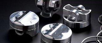
In this section we collect accumulated information on the parameters of serial and tuning parts - weight, volume, and other quantities. For parts, the manufacturer (optional) and other parameters are indicated. The weight of parts is measured with an accuracy of 1 gram. This information should be used for reference purposes only. We warn you that due to imperfect technological processes at factories, the weight and other parameters of parts in different batches may differ. For Oka, we remember about the unification with the 08 family (1111 = 2108, 11113 = 21083). _______ Weight of parts (in grams) Pistons, pins
Piston 2110 (1st repair, d = 82.4 mm, group A), VAZ 357 Piston 21083 (nominal, d = 82.0 mm, group A), VAZ 335 Piston 2108 (nominal, d = 76.0 mm , group B), VAZ 286 Piston pin 21083, VAZ 103
82.00 “SM” 1 compression ring
8 82.00 “SM” 2 compression ring
11 82.00 “SM” oil scraper ring set (2 discs + spring)
Connecting rod 2108, VAZ 671 Connecting rod 2110, VAZ (for floating pin) 680
21083 standard inlet 37x8x104 mm "SZK" lightweight "T-shaped" lightweight "tulip" 80 57 55 21083 standard exhaust 31x8x104 mm "VAZ" lightweight "T-shaped" lightweight "tulip" 72 52 50 2101 "classic" standard inlet 37x8x112, 5 mm “SZK” lightweight “tulip” 81 57 2101 “classic” standard edition 31.5x8x113.5 mm “SZK” lightweight “tulip” 71 54 Valves 39x34
“STK Sport” intake 39x8x104 mm, lightweight at the end, enlarged tulip
67 65 60 “STK Sport” release 39x8x104 mm lightweight at the end, enlarged tulip
67 61 57 Valves 42x35
BMW intake 42x8x104 mm lightweight 85 58 BMW exhaust 35x8x104 mm lightweight
79 52 Valves 40x35 stem 7 mm
BMW intake 40x7x103 mm lightweight 69 52 BMW exhaust 34x7x103 mm lightweight
60 46 Valves 41x35 (rework 41x38) stem 7 mm, VAZ “Classic”
(import) inlet 41x7 mm lightweight 91 soon (import) exhaust 38x7 mm 35x7 lightweight
87 soon Valves UZAM 1.7 40x34 stem 8 mm
UZAM inlet 40x8x117 mm lightweight 82 65 UZAM outlet 34x8x112 mm lightweight
69 61 Valves 2112 standard stem 7 mm
2112 lightweight inlet - 39 2112 lightweight exhaust
2108 The upper spring plate (modified OKB according to the cone) 16 2108 The upper spring plate (modified according to planes) 14 2108 The upper duravaya springs (Togliatti pr-va) 9 2101 upper lines (modified according to the planes) 20 2108 Standard pusher 47 2108 adjusting adjustment adjustment control washer 4.00 mm 24 Adjustment post for one-piece pusher 5.55x8 mm 2 2108 One-piece valve pusher (Moscow) 50
_______ Duralumin spring plates in comparison with standard ones, grams Serial spring plate 2108, Oka (material - steel) 16 Duralumin spring plate 2108, Oka 6 Serial spring plate VAZ "Classic" (material - steel) 21 Duralumin spring plate VAZ "Classic" 9 Serial spring plate UZAM (material - steel) 25 Alloy spring plate UZAM 10 Serial spring plate ZMZ 402 (material - steel) 32 Alloy spring plate ZMZ 402 14 Serial spring plate BMW M10 (material - steel) 16 Alloy spring plate BMW M10 8
_______ Volumes of samples (parts of the combustion chamber) in detail (cm3) Piston 2110 (1st repair, d = 82.4 mm, group A), VAZ 12 Piston 21083 (nominal, d = 82.0 mm, group A), VAZ 12 Piston 2108 (nominal, d = 76.0 mm, group B), VAZ 6 Combustion chamber in the cylinder head 2109i (standard - undershot? SZh 10.4) 22 Combustion chamber in the cylinder head 2101 - VAZ classic 31
_______ Internal diameters of cylinder head seats and valve sizes (mm) cylinder head 1111 (650 cc) intake seat after boring 30 31 cylinder head 1111 (650 cc) exhaust seat after boring 27.5 29 cylinder head 11113 (750 cc) intake seat after boring
cylinder head 11113 (750 cc) exhaust seat after boring cylinder head 2101 (classic) intake seat after boring 31.5 31 cylinder head 2101 (classic) exhaust seat after boring 27 31 cylinder head 1111 (650 cc) standard valve plate size 35x31 cylinder head 11113 (750 cc) ) standard valve disc size 37x31 cylinder head 2101 (classic) standard valve disc size 37x31
_______ Diameters of the channels in the cylinder head at the inlet from the manifold side (mm) cylinder head 1111 (650 cc) intake port after boring 27.5 31 cylinder head 1111 (650 cc) exhaust port after boring 27 31 cylinder head 2101 (classic) intake port after boring 29, 5 cylinder head 2101 (classic) exhaust channel after boring 26.5
Adjusting washers for VAZ 2108 valves from 2.00 mm to 5.30 mm.
The diameter of the washer is 31 mm.
Specifications:
- Surface hardness - 60-63 HRC;
- Core hardness - 294 HV5 / 29.0 HRC;
- Effective layer thickness h=1.06 mm (up to 525 HV5);
- Layer microstructure: martensite, residual austenite;
- Core microstructure: bainite, ferrite.
The washers are manufactured in compliance with the manufacturer's technology. Quality is guaranteed by multi-stage control. You can get advice about the product by ordering a call back (tab on the left).
The following configurations are possible:
- from 2.00 mm to 5.10 mm. — 125 pieces (1 piece of each size);
- from 2.62 mm to 5.10 mm. — 100 pieces (1 piece of each size);
- from 3.00 mm to 4.22 mm - 100 pieces (2 pieces of each size);
- from 2.30 mm to 4.77 mm - 100 pieces (1 piece of each size).
We accept orders for sets of washers (any size and quantity specified by you).
The following sizes are also available: 1.80; 1.82; 1.85; 1.87; 1.90; 1.92; 1.95; 1.97 mm.
New washer sizes have appeared from 5.10 to 5.30 (see the sizes in the table in photo No. 6).
Wholesale price 35 rub. when ordering 50-99 pcs. Wholesale price 34 rub. when ordering from 100 pcs.
Approximate weight of a set of 100 washers: 2400-2700 g.
Valve shims
It's easy to place an order on our website. Simply add the selected items to your cart, then go to the Cart page, check that the items you ordered are correct, and click the “Checkout” or “Quick Order” button.
The “Quick Order” function allows the buyer not to go through the entire ordering procedure on their own. You fill out the form, and after a short time the store manager will call you back. He will clarify all the conditions of the order, answer questions regarding the quality of the product and its features. It will also tell you about payment and delivery options.
Based on the results of the call, the user either, having received clarifications, places an order independently, completing it with the necessary items, or agrees to the order in the form in which it is now. Receives confirmation by email or mobile phone and waits for delivery.
Placing an order in standard mode
If you are confident in your choice, you can place your order yourself by filling out the entire form step by step.
Filling out the address
Select the name of your region and locality from the list. If you did not find your locality in the list, select “Other location” and enter the name of your locality in the “City” column. Enter the correct index.
Depending on where you live, you will be offered delivery options. Choose any convenient method.
Choose the optimal payment method.
Enter your information: full name, delivery address, phone number. In the “Comments to the order” field, enter information that may be useful to the courier, for example: entrances in the house are counted from right to left.
Does the marking correspond to the actual thickness?
There is an opinion that the actual thickness of the adjusting washers is far from the nominal value. In other words, its actual size does not always correspond to the indicated one. Therefore, before buying a washer, you must measure it with a micrometer. So I decided to figure out how reliable this information is and whether a control measurement of the adjusting washer before measurement is of fundamental importance.
I did not conduct large-scale research, so my conclusions should not be taken as the “ultimate truth,” but, nevertheless, certain conclusions can be drawn.
Micrometer Caliber MK-25
As a measuring instrument, I used the Caliber MK-25 micrometer, produced in 1964 by the instrumentation plant of Kalibr OJSC. The instrument was preserved in perfect condition, since it lay idle for decades in the garage of one “enterprising” grandfather, who, even in his youth, worked to make this instrument his personal property. By the way, this grandpa still doesn’t know what kind of tool this is and what it’s needed for :)).
In short, I purchased this useful “device” for a symbolic 1,500 rubles and began measuring the shims. At one time, I myself worked at a factory for several years as a machine operator, so I am familiar with measuring tools firsthand. My point is not to tempt anyone to write any nonsense in the comments regarding the preliminary check of the measuring device for accuracy (calibration, etc.). I took care of everything before taking measurements. So let's get started.
Adjusting washer No. 1 marked 3.55 mm
The thickness of the first washer in fact turned out to be 2 acres greater than indicated by the marking. Let's move on to measuring the next washer.
Adjusting washer No. 2 marked 3.45 mm
The thickness of the second washer in fact turned out to be greater than indicated by the marking by 2 hundred parts, just like the first. Let's move on to measuring the next washer.
Adjusting washer No. 3 marked 3.57 mm
The thickness of the third washer in fact turned out to be 1.5 hundred parts greater than indicated by the marking. Let's move on to measuring the next washer.
Adjusting washer No. 4 marked 3.75 mm
The thickness of the fourth washer in fact turned out to be 2 acres greater than indicated by the marking. Let's move on to measuring the next washer.
Adjusting washer No. 5 marked 3.70 mm
The thickness of the fifth washer in fact turned out to be 1.5 hundred parts greater than indicated by the marking. Let's move on to measuring the next washer.
Adjusting washer No. 6 marked 3.60 mm
The thickness of the sixth washer in fact turned out to be greater than indicated by the marking by 1 hundred square meters. Let's move on to measuring the next washer.
Adjusting washer No. 7 marked 3.42 mm
The thickness of the seventh washer in fact turned out to be 3 acres greater than indicated by the marking. Let's move on to measuring the next washer.
Adjusting washer No. 8 marked 3.55 mm
The thickness of the eighth washer in fact turned out to be 2 acres greater than indicated by the marking. Let's move on to measuring the next washer.
Adjusting washer No. 9 marked 3.85 mm
The thickness of the ninth washer actually coincided with the marking. There are no deviations. Let's move on to measuring the next washer.
Adjusting washer No. 10 marked 3.65 mm
The thickness of the tenth washer in fact turned out to be 2 hundred parts greater than indicated by the marking. Let's move on to measuring the next washer.
Adjusting washer No. 11 marked 3.47 mm
The thickness of the eleventh washer in fact turned out to be 3.5 acres greater than indicated by the marking. This is an anti-record :)). Let's move on to measuring the next washer.
Adjusting washer No. 12 marked 3.62 mm
The thickness of the twelfth washer in fact turned out to be greater than indicated by the marking by 1 hundred square meters. Let's move on to measuring the next washer.
Adjusting washer No. 13 marked 3.80 mm
The thickness of the thirteenth washer actually coincided with the marking. There are no deviations. Let's move on to measuring the next washer.
Adjusting washer No. 14 marked 3.52 mm
The thickness of the fourteenth washer in fact turned out to be greater than indicated by the marking by 1 hundred square meters. Let's move on to measuring the next washer.
Adjusting washer No. 15 marked 3.52 mm
The thickness of the fifteenth washer actually coincided with the marking. There are no deviations. Let's move on to measuring the next washer.
Adjusting washer No. 16 marked 3.87 mm
The thickness of the sixteenth washer in fact turned out to be 0.5 hundred parts greater than indicated by the marking. This completes the measurements.
How to adjust valves on a VAZ 21099
- If the car has been driven, leave it to cool with the hood open for 2-3 hours;
- Disconnect the throttle cable and its support from the throttle;
- Disconnect all connected pipes from the valve cover;
- Unscrew the two nuts securing the valve cover and remove the cover;
- Jack up the front right wheel;
- We engage fifth gear at the gearbox;
- We turn the engine until the first cylinder is installed at TDC;
- We attach a device for adjusting the valves to the valve cover bolts;
- We adjust the thermal clearances of the valves by turning the engine by the raised wheel;
- After adjusting the valves, we assemble everything in the reverse order.
For details of the entire procedure for adjusting the valve clearances of the VAZ 21099, see the photo report.
Let's start adjusting the thermal clearances of the valves. Before us is a regular VAZ engine with a volume of 1.5 liters.
The first thing we will do is remove the throttle cable. Unscrew the two bolts securing the bolt bracket, using a 10 mm wrench.
Use a screwdriver to pry up the cable fixing bracket and remove it.
We twist the cable and pull out the cable end from its seat on the throttle.
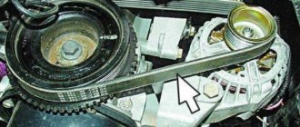
Having removed the cable, we will disconnect all pipes from the valve cover. Unscrew the clamps indicated by the arrows.
And from the front of the engine we remove the crankcase gas pipe.
Now we just have to unscrew the two nuts securing the valve cover. For this we use a 10 mm wrench.
And remove the cover from the engine.
Jack up the front right wheel and engage fifth gear at the gearbox. This way we can crank the engine by spinning the wheel. It is recommended to turn clockwise, as the engine itself works.
To adjust the valves we need a special device. We screw it to the valve cover mounting studs, as shown in the photo.
Using a syringe with a hose, we remove all the oil in the wells between the valves so that it does not interfere with us adjusting the valves.
In order not to remove the timing case and not bother with the procedure for adjusting the valves, we will adjust the valves in the cylinder where the camshaft cams point up. The engine cycle is cylinders 1, 3, 4, 2, so we adjust the valves in that order. At the moment, our cams are raised on the second cylinder, and here we check what gap is between the valve and the camshaft. If the clearances are in order, then turn the engine clockwise until the camshaft cams on the first cylinder rise up and measure the clearances.
If the gap is not correct, we will have to change the adjusting washer to a washer with the required size. We rotate the valve cup so that the slot indicated by the arrow is facing us. Using the previously screwed device, we press the valve, pressing the lever.
Included with the device for adjusting the valves is a clamp necessary to fix the valve in the pressed position.
We install the retainer between the valves, as shown in the photo.
We remove the lever that was used to press the valve, and we see how the latch, resting against the camshaft, holds the valve pressed by the edge of the cup.
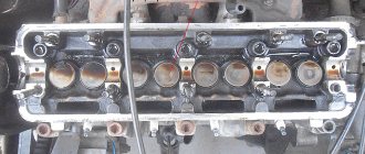
Interaction of gas distribution mechanism parts
The camshaft, rotating, presses the cams onto the adjusting washers, which are located in the pushers mounted on the ends of the valve stem. Thereby pushing the parts whose caps are located in the valve seats. The seats and caps are very precisely ground to each other, this is done so that at the moment when the cap of the part is completely seated, a hermetically sealed connection is formed into the saddle. The channel is completely blocked.
This is why the engine runs stably and produces the required power, saving fuel. As the engine operates, the working surface of the cams wears out, they lose their dimensions, and the gaps increase.
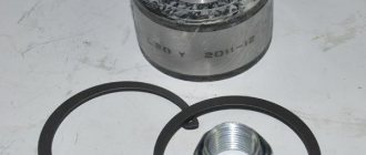
Because of this, the caps do not fully adhere to their saddles, as a result of which the tightness of the saddle-cap connection is lost. In order to restore this tightness, adjustment of the VAZ valve clearances is required. For this purpose, adjusting washers are used. These washers themselves are round in shape and the circumference diameter is the same as that of the pusher (pos. A in the figure above). The photo below shows some examples of these round washers:
Here are eight washers of different thicknesses. The thickness is written on the washer itself in millimeters. Valve clearances are adjusted by selecting washers of the required thickness. Sometimes you have to change these washers several times, each time inserting a washer of a different thickness, until the valve clearance reaches the desired size.
The procedure for adjusting the thermal clearances of valves on VAZ 2109-21099
Attention! The car engine must be cold and its temperature at the time of adjustment should not be higher than 20 degrees.
Video tutorial on how to do the job
In order to clearly demonstrate the procedure for adjusting thermal gaps, it was decided to record a special video clip that shows everything in detail.
If from the guide presented above there is something still unclear to you, then below everything will be presented in a form familiar to everyone.
Photo report of the performed maintenance
So, before proceeding with this operation, you first need to remove the valve cover, as well as the casing under which the timing mechanism is located.
After this, you need to set the gas distribution mechanism according to the marks. To do this, jack up the front right part of the car so that you can turn the wheel by hand to set the valve timing marks.
Then we turn the wheel until the marks on the camshaft sprocket and the marks on the rear timing cover align, as clearly demonstrated in the picture below:
At the same time, make sure that the mark on the flywheel also coincides with the cutout. You need to look through the window, which is located to the right of the fourth cylinder on the gearbox housing. You must first remove the rubber plug:
When the camshaft is in this position, you can begin to measure the thermal clearances between the cams and pushers of the 1st, 2nd, 3rd and 5th valves (counting from the left):
For intake valves, the nominal clearance should be 0.20 (+-0.05) mm, and for exhaust valves 0.35 (+-0.05) mm. If you don’t know the location, I can say: from left to right in order: exhaust-inlet, inlet-outlet, etc.
If, when measuring the gaps, they go beyond the maximum permissible values, they must be adjusted by installing new shims. To do this, we put the bar on the valve cover studs and secure it with nuts.
Now we bring the mechanism lever to the desired valve, and direct it as if between the pusher and the camshaft cam, and recess the valve to the very end:
And when the pusher is pressed down as much as possible, you need to insert a clamp between the camshaft and the pusher:
It is worth noting that the cutout on the pushrod should be facing towards you so that you can conveniently remove the shim. It is very convenient to use long-nose pliers for this:
After that, look at its size, which is indicated on its back side:
Now we calculate, based on the measured gap and the thickness of the old washer, what the thickness of the new washer should be in order to achieve the optimal gap.
Now you can insert the new washer into place and make further adjustments. When the first 4 valves are ready, you can turn the crankshaft one revolution and carry out a similar procedure with the remaining 4, 6, 7 and 8 valves.
Good day. Tell me how to estimate the required thickness of the washer under the following conditions: after assembling the cylinder head in the garage, a mechanic and I were forced to cut off the thickness of the standard washer on the 1st and 3rd outlet valves to a gap of 030+005. Engine 21083 injector with a mileage of 170 t.km. The positions of the service technicians have changed to a worse position for the car enthusiast whose car is not a luxury. The latter are drawn to old-school craftsmen and production areas with mechanical processing of the cylinder head. The event of milling the surface of the cylinder head abutment to the block and replacing valves one or two valves with lapping creates a situation: at the mechanical processing area there is no equipment for adjusting the valve with the cylinder head dismantled. And during the assembly of the cylinder head into the engine, the assembly mechanic involuntarily cuts off standard washers for a large 030 -040 thermal gap on the repair valve in order to allow the car, under its own power, without damaging the same valve from a heated engine, to reach the point of adjusting the thermal clearance of the valves using washers.
one revolution is 360 degrees, the valves will return to their original position
No, they won't get up! One revolution of the crankshaft is only half a revolution of the camshaft!
So now I’m setting the gaps, first measured, do 1 revolution of the crankshaft and the shafts return to their original position, what the fuck
Egor, learn the material part or open the 9th grade Physics textbook and read FOUR STROKE internal combustion engines and you are talking about two-stroke engines. In short, like a peasant, when turning the crankshaft by 180 degrees, the mark on the camshaft gear is installed opposite the original one, but the gearbox does not match the gearbox and that’s all. In the initial position when the mark on the camshaft gear matches and in the gearbox hatch, adjust valves 1-3 and 2-5, and when turning 180 degrees, when the mark is opposite the original one but does not match, in the gearbox hatch you adjust 4-7 and 6-8
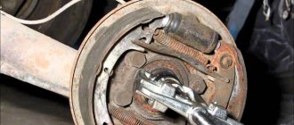
Replacing seats
The replacement procedure consists of two important procedures: removing old parts and installing new ones.
Removing old planting elements
Replacement of valve seats is carried out on a dismantled cylinder head with a disassembled gas distribution mechanism. You can remove the old ring using a welding machine, if the material from which it is made allows this.
To perform the procedure, a valve seat remover is made - an old unnecessary valve is taken, the plate of which must be machined to the size of the inner diameter of the seat.
After this, the resulting tool is recessed into the seat, 2-3 mm short of the edge, and “grabbed” by welding in 2-3 places. Afterwards, the valve along with the metal ring is knocked out from the back side with a hammer.
Valve seats made from non-weldable metals can be removed by screwing a piece of pipe into the seat as a valve seat remover. To do this, a thread is cut on the inner surface of the ring. A similar thread is applied to the outer surface of a metal pipe of suitable diameter.
An old valve is taken and first welded to the end of the pipe in the reverse position. In this case, the valve stem is inserted into the hole intended for it, the pipe is screwed into the thread, after which the element is removed by tapping the stem.
Installation of new saddles
Before starting the installation procedure of new saddles, the seats under them are cleaned of dirt. After the cylinder head should be heated evenly to a temperature exceeding 100˚C. At the same time, the metal expands, allowing the ring to be pressed in.
The mounted part is cooled using liquid nitrogen. In its absence, you can use a combination of ice and acetone, which allows you to reduce the temperature of the metal to -70˚C. The dimensions of the parts are selected in such a way that the difference between the diameter of the seat and the ring is no more than 0.05-0.09 mm on cold parts.
The valve seat is pressed into place using a special mandrel or a piece of pipe of suitable diameter. The part should fit into the seat with little effort
In this case, it is important that the ring fits without distortion
After pressing in and cooling the cylinder head, you should check whether the element is loose in the seat. If there is no gap and the replaced element is held tightly in place, the replacement procedure can be considered complete. Next, you need to trim the valve seats using cutters.
Article: 2108-1007056-*2.85, additional articles: 2108-1007056
Order code: 029170
- You may need
- show more
- Passenger cars / VAZ / VAZ-21091 drawing
- » href=»/catalog/vaz-3/legkovye_avtomobili-30/vaz_2109-9/mehanizm_gazoraspredelitelnyiy-81/#part32142″>Adjusting washerEngine / Gas distribution mechanism
- Passenger cars / VAZ / VAZ-21101 drawing
There are no reviews for this product yet.
Welcome to the blog.
A client came in for an adjustment. Previously, we measured the compression in the 3rd cylinder; the compression was low, so we decided to start with adjustment.
1. Remove the head cover 2. Remove the front timing belt cover 3. Use a syringe or rubber bulb to remove any remaining oil around the valve tappets.
a) for intake valves Z = Y + X - 0.2 mm;
b) for exhaust valves Z = Y + X - 0.35 mm;
where Ζ is the calculated thickness of the new adjusting washer; Υ is the thickness of the removed washer; X is the gap determined by the feeler gauge. Adjustment table
15. Having removed the device for adjusting the valves, install the parts in the reverse order of removal.
After the adjustment, I measured the compression, namely, I focused on the 3rd cylinder, the compression increased, became the same as in all pots, the engine began to run noticeably quieter and smoother)))
P.S. Sorry for the pictures, after the first steps, my hands were clean, when it came to the pucks, my hands were just covered in oil, I didn’t feel like taking pictures, I didn’t want to get the camera dirty.
Thank you for attention! Stay tuned, stay true!
Drawing conclusions
Before drawing any conclusions, for ease of perception, all the obtained measurement results were entered into a comparative table.
Below we will look at all the given indicators, but first we will answer the question: why did I use exactly 16 shims in my measurements, and not 20 or 10? Everything is very simple. The washers in the table are divided into two groups:
- Washers installed from the factory. Since there are 8 valves in the engine, there are also 8 adjusting washers;
- Washers bought in a store. There are also 8 of them, since they were purchased to replace the old one installed from the factory.
Let's move on. In the “Marking” column, I wrote down the nominal size of the shims, which is indicated on the washer.
And in the next column “Actual thickness” I wrote down the actual thickness of each of the adjusting washers.
In the last column “Deviation” I recorded the deviation of the adjusting washer from the nominal size or the so-called error.
Conclusion one: there are no perfect washers
Please note that the deviations of washers installed from the factory are almost the same as those of washers purchased in a store. This means that all shims have errors, and this is normal. The factory does not install any “super washers” with zero deviation from the nominal value.
Conclusion two: the tolerance ± 0.05 mm is due to the error of the adjusting washers
Why can we conclude that the tolerance of ± 5 acres indicated by the manufacturer is due to an error in the actual thickness of the adjusting washers? If you pay attention to the table, everything will become clear.
As you noticed, the largest deviation from the “norm” was only 3.5 acres. And if we take the average deviation, it is even less.
On average, the deviations or errors of the adjusting washers are only 1.5 hundred parts. What's all this for?
Conclusion three: shims don’t need to be measured
There are two approaches to adjusting valves and each of them has a right to life. How to use it is up to you to decide. A little more detail.
- Selecting washers using a micrometer. A more accurate but also more labor-intensive process because the thickness of each washer is determined by measuring it with a micrometer rather than marking it. The size of the washer will need to be marked and recorded separately to avoid confusion.
- Selection of washers without a micrometer. If you don’t have this device or don’t know how to use it, it doesn’t matter. Focusing only on the markings of the washers, you can accurately adjust the valves. In this case, the thermal clearances of the valves will still be within the “tolerance” of 5 acres. The only disadvantage of this method is that you will be forced to buy shims only from a trusted supplier. The desire to find something cheaper, via the Internet or in a “neighbor’s garage,” will be associated with certain risks, because now everything is counterfeited!
The first method is certainly better and more reliable, but if you nevertheless installed washers that were not checked with a micrometer, focusing only on the markings, do not worry, nothing will happen to your engine. He will definitely “live” until the next adjustment.
If there is no valve adjuster
The functions of special equipment can be assigned to two powerful flat-head screwdrivers with a flat working surface width of at least 10 mm. In this case, setting the clearances of certain valves on the VAZ 2108 is carried out as follows:
- press the pusher down, leaning on the cam;
- remove the first screwdriver;
- remove the washer with tweezers;
- install a new part;
- remove the second screwdriver, which acts as a lock.
install the edge of a screwdriver between the camshaft and the pusher;
The process of adjusting the valve mechanism is carried out every 20-30 thousand km and is carried out with the cylinder head cover removed. At a certain angle of rotation of the camshaft, the gap between two pairs of valve tappets and cams is checked with a feeler gauge.
Adjustment of the gaps should be resorted to in case of significant deviations from the norm: 0.15...0.25 mm for intake and 0.30...0.40 mm for exhaust. Using a special device or two screwdrivers, the pusher is bent and fixed, the old washer is removed, a washer of a new thickness is installed, the lock is removed and the resulting gap is checked.
Initial stage: opening access to the camshaft
The proper conditions under which the valve assembly is adjusted are formed after dismantling the cylinder head cover. You can easily remove the upper cylinder head housing with gasket after performing the following procedures:
- loosen the cable by rotating the two nuts to “13” near the bracket and remove it, after first removing the return spring on the plastic sector of the damper drive;
- Using a 10mm wrench, unscrew the two nuts securing the throttle cable bracket and remove it;
- Loosen the fastening clamps with a screwdriver and remove the inlet (located on the front side near the oil filler neck) and two outlet pipes for the crankcase ventilation (attached to the back of the valve cover);
- Unscrew the two nuts securing the housing to the cylinder head (use a “10” wrench);
- remove two rubber plugs located under the nuts already removed in the previous transition.
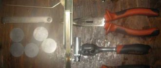
At the end of the preparation stage for adjusting the valve clearances of the VAZ 2108 engine, an operation is carried out to remove the gas distribution mechanism cover, which is secured with three “10” bolts. A set of necessary accessories is also formed:
- device for recessing the pusher;
- a special clamp that secures the pusher in the lower position;
- tweezers;
- valve tappet retainer;
- set of measuring probes;
- set of adjusting washers.
It is also worth preparing a new cylinder head gasket and sealant.
Why do you need valve adjustment on a figure eight?
We have gradually arrived at a very interesting question, what if. What if you didn’t or for some reason forgot about the need for periodic adjustments. It is worth understanding that the design of the VAZ 2108 engine leads to the fact that the gaps decrease over time, which, at best, negatively affects the dynamic characteristics of your iron horse, and fuel consumption, on the contrary, increases. The most advanced cases provoke increased wear of the main parts of the power unit, including:
- camshaft;
- the valve seat and even the adjusting washers themselves burn out;
- The problem may also occur with the pushrod (rocker) and valve system.
In order not to provoke premature aging of your stallion, turning him into a sluggish, tortured horse, you should not forget about the need for periodic maintenance of the valve head on the VAZ 2108, and we also advise you to carefully listen to the sounds from the power unit when the car is running. A sure signal for action is the characteristic clattering sound emitted from the top of the internal combustion engine (actually, from its “head”), the first thing that suffers in this case is the saddle. Well, in order to become a sophisticated specialist in the matter of adjusting VAZ 2108 valves, all you have to do is familiarize yourself with the practical part of this article and get a little experience.
There is a better option...
The most basic and expensive type is the roller pusher. The range of positive indicators of this “friend” is extremely wide. It compensates for almost all the shortcomings of its previous brothers, but at the same time has additional advantages. Thus, during operation, it is able to reduce the friction force of the valves, thereby increasing the power of the internal combustion engine, and its ability to supply fuel economically allows us to consider this analogue the best in its series. They come in both mechanical and hydraulic types.
When choosing, you should pay attention to the characteristics of a single pusher, since it is difficult to immediately say which one will be better. It should only be clarified that a mechanical pusher will be the worst option for forced operation of the VAZ 2109 internal combustion engine
The main assistant in the operation of any pusher is the cam camshaft. We do not recommend discounting this comrade - the work of the pushers directly depends on the selected brand of camshaft. So, for example, if you select the wrong cam for the pusher, the supply of the air-fuel mixture and the exhaust gas will be disrupted due to uneven opening of the valves. Not only is this not economical, it is also dangerous for the life of your internal combustion engine. The consequences of such work are scary to imagine.