When the gas pedal is not pressed and the gear shift knob is in the neutral position, the internal combustion engine idles. Since the throttle valve is closed in this position, to maintain the required speed within 800-900 rpm, the required amount of air is supplied to the intake manifold through the actuator - the idle air control.
Idle speed sensor for VAZ 2114
After cleaning the throttle body the speed fluctuates
So, it would seem that the whole procedure is over. The damper was cleaned with a cleaner, the air filter was replaced with a new one, the sensors were reconnected, that is, everything was assembled and tightened. Now you can proceed to starting the engine. If the engine starts after cleaning the throttle valve and then runs normally, then the procedure can be considered successful.
It should be added that this is not always the case. Many people are faced with the fact that after cleaning the throttle valve, high engine speeds remain constant and do not drop. Also, many drivers notice that after cleaning the throttle valve, fuel consumption has increased. A likely cause could be an error in connecting some sensor during reassembly, but this rarely happens.
Most often, after cleaning, the throttle also needs to be additionally calibrated and adjusted, which not everyone knows about or does it incorrectly. In other words, high idle speeds after cleaning the throttle valve are a clear example and at the same time an answer to the common question of whether the throttle valve needs to be trained after cleaning this unit. Let's figure it out.
Let's start with the fact that in some cases a pure throttle valve really needs to be adapted (trained). Typically, throttle valve adaptation is often necessary when the electronic throttle valve has been cleaned before. There are fewer problems with a mechanical damper, but they still exist. In systems with an electronic throttle, the ECU independently sets the throttle position; in mechanical systems, the idle air control is set. To put it simply, after removing the layer of dirt, the position of the cleaned damper changes, but the ECU does not know about this and continues to supply fuel in accordance with the previous parameters before cleaning. To solve the problem, it is necessary to set the idle speed using diagnostic equipment, since it is possible to reset the previous parameters.
You can also try teaching the throttle manually. The simplest way to learn without diagnostic equipment or a scanner for adaptation is to unscrew the negative terminal of the battery from a few seconds to 10 minutes (depending on the make and model of the car). This allows you to reset the settings, that is, the existing adaptation is reset and returned to the factory settings. After connecting the terminal to the battery and restarting the engine, the idle speed should stabilize.
Note that this method works on a limited number of cars. In such a case, you can take advantage of another opportunity to train the throttle assembly without a computer. This method is suitable for a range of vehicles from different manufacturers. Let's consider such an adaptation using the example of a Japanese Nissan car.
- First, the engine must be warmed up to operating temperature, after which the engine should be turned off.
- Next, you will need to wait 5-10 seconds, then turn on the ignition for 3 seconds.
- Now you need to press the gas pedal all the way and immediately release it. This is done 5 times, you need to do it in 5 seconds (one press per second). The interval should be timed using a stopwatch so as not to get lost.
- After the last press, you should wait 7 seconds, after which the gas pedal is again pressed “to the floor” and held in this position until the “check” begins to blink on the dashboard, and then this light comes on constantly.
- After the moment when the check code starts to light up constantly, you need to wait another 3 seconds. Now the gas pedal can be released.
- Next, the engine needs to be started, the idle speed should return to normal.
Let us add that during such adaptation of the throttle valve it is important to accurately maintain the timing at each stage, as well as to fit into all time intervals. In this case, we can talk about successful training.
It is also recommended to clarify the features and the possibility of manual adaptation for a specific car model.
How to change dhx on Priora
Before checking the functionality of the controller, the ignition system is turned off and the negative terminal from the battery is removed. These are simple safety rules when working with vehicle electrical wiring and controls. Procedure for replacing dhx.
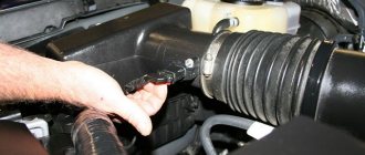
- Open the hood and remove the plastic engine protection cover.
- The DXH is located in the throttle block, on the right side of the car.
- Remove the wire connector from the regulator.
- Use a Phillips screwdriver to remove two bolts.
- Dismantle the element.
After removal, the part is carefully inspected, cleaned and initial diagnostics are carried out. To do this, you need to insert the wire block into the sensor and turn on the ignition. Once connected, the working unit will respond with a noticeable movement of the rod needle. If this does not happen, the wiring is checked and the part is reinstalled with a new one.
Checking with a multimeter
More accurate diagnostics are carried out using a tester. First of all, the quality of the power supplied to the connector is checked. To do this, the multimeter probes are connected to the terminals of the block (chips). The voltage supplied to the dhx is within 20 V, the permissible deviation is 1–2%.
The regulator is checked by measuring the resistance on the winding. The multimeter is switched to resistance measurement mode, the tester probes are connected, the operating voltage is 52–53 Ohms, the permissible deviation is 1–3%.
In most cases, the DXH cannot be repaired, since the main malfunction is a breakdown of the electric motor and wear of the needle. The node is replaced with a new one. After replacement, it is necessary to “register” the regulator in the IAC control circuit. Original components are sewn into the ECU independently after the second engine start. It is necessary to reinstall the sensor, start the engine, stop the ignition and start the engine a second time.
Self-checking and replacing the controller takes up to 15 minutes and can easily be done in the garage. When choosing spare parts for the Niva, it is recommended to use only factory components or original replicas.
Second way
For this testing option, you will need a simple tester that you can easily make yourself. We offer corresponding video instructions
Now we proceed as follows.
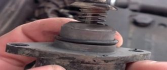
- Unscrew the fastening screws of the regulator and remove it from its seat.
- The location of the DXX is already well known to you.
- Disconnect the regulator from the main block, and apply the finger of your right hand.
- And the index finger. You don't need to put a lot of effort into creating a set.
- The nuance of placing a finger lies in the features of the regulator itself, at the end of which there is a cone-shaped needle.
- If the engine stops working, then if the IAC is working properly, the needle comes out completely.
- Your finger will allow you to feel a slight jolt when you turn on the ignition.
- If this push is absent, then the device has failed.
The maximum distance from the protruding rod head to the flange is 23 millimeters. When buying a new IAC, be sure to take this fact into account.
Throttle position (DZ position)
Despite all of the above, measuring the throttle position plays, although not the main, but very important role in the process of engine control. It helps you manage processes more accurately.
For example, an engine operating mode such as forced idling or cut-off mode (engine braking). The throttle position helps the ECU assess the situation and enable this mode.
Let's say the car speed is 55 km/h and the engine speed is 2600 rpm. We release the accelerator pedal, the throttle position becomes minimal, the ECU sees this and turns on the cut-off mode, turning off the fuel supply through the injectors. This allows you to use engine braking more effectively, increasing safety and extending the service life of the braking system, as well as saving fuel and significantly reducing the emission of harmful substances into our atmosphere.
But I’m lying if I don’t say that the ECU will already see that we have closed the damper due to a sharp drop in pressure in the intake manifold (with a DBP system) or a sharp decrease in the mass of air consumed (with a mass air flow sensor system). As we can see, in this case too, measuring the throttle position only helps to more accurately determine the cutoff or engine braking factor.
Operating principle of the idle speed sensor
When the driver takes his foot off the gas pedal, the throttle valve closes completely. All the air required for idle operation (idle) enters through a separate channel, partially blocked by a software-controlled valve. It is the gap between it and its socket that determines at what speed the engine will operate.
The regulator is a stepper motor with two armature windings. One of the windings is designed to move the rod forward, to close the channel, the second - in the opposite direction. Each bipolar pulse applied to the winding by the controller causes the rod to take one step. A full move is 255 steps.
There is no feedback, that is, to accurately position the valve, the controller counts the number of pulses. And the initial information is a comparison of the number of current crankshaft revolutions with the specified program.
Let's say the engine is warmed up, but the IAC rod position memory is reset (the power was turned off). The controller needs to set the required 850 rpm to XX. He doesn't know what position the valve stem is in.
In this case, all 255 forward stroke pulses are sent to the IAC so that the rod is guaranteed to move forward and completely block the air channel. After this, you can issue the number of reverse pulses specified by the algorithm, ensuring the initial gap in the channel. This will set up the initial setup.
Next, the control mechanism based on signals from the crankshaft sensor will come into play. Knowing how many pulses are received from it per unit time and how many of them are per revolution, you can calculate the rotation speed and, by changing the bypass cross-section, adjust the required revolutions. All processes occur quickly, only a slight chirping of the IAC stepper motor is heard.
Tips for extending the service life of IACs
To increase the service life of the sensor, you need to follow simple rules:
- The air filter device must be replaced on time.
- You cannot park your vehicle for long periods of time in winter. At low negative temperatures, the car owner must periodically start the power unit, warm it up and perform gas changes. This will allow the valve to be designed to prevent it from sticking.
- Do not allow foreign liquids to enter the throttle mechanism area. Sprays for quick starting of the engine usually do not pose a danger to the sensor, but it is better not to overdo it.
Malfunctions of the idle air regulator and its check
In cars equipped with an injector, a separate actuator (IAC), controlled by a controller, is responsible for engine idle speed and cold start.
Although its design is simple and reliable, during the operation of the car the element may not work correctly or, like any other part, fail due to natural wear and tear.
How to identify symptoms of a malfunction and check the idle air control in a garage is described in detail in this publication.
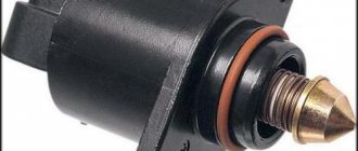
How does the regulator work?
In everyday life, the IAC is often called a sensor, although in reality it is not one. The element is a stepper motor housed inside a non-separable housing. Only the spring-loaded rod with a cone-shaped tip protrudes outward. At the command of the ECU, the engine extends or retracts the rod to a certain distance.
The idle speed sensor is located in the throttle valve block, the working cone is extended into a small cross-section bypass channel.
Since the engine starts and idles without pressing the accelerator pedal, the mentioned channel supplies air to the cylinders when the throttle is closed.
The task of the IAC is to regulate the amount of air flow, blocking part of the flow area with a cone.
- After the driver turns on the ignition, the controller activates the governor motor, forcing the idle air passage to open. The ECU calculates the opening amount using a temperature sensor - if the engine is cold, the rod will move back more.
- At the moment of startup, the injectors supply an enriched mixture to the cylinders. Then the amount of fuel is reduced so that the engine does not “suffocate” and stall. The speed is monitored by the control unit using a crankshaft position sensor.
- The volume of air entering through the IAC is taken into account by the mass air flow sensor located on the inlet pipe, while increased crankshaft speeds are maintained (1200–1500 rpm).
- Using the temperature sensor, the control unit “sees” that the engine is warming up and gradually reduces idle speed, giving the command to the IAC to cover the cross-section of the bypass channel. When the temperature reaches an acceptable value (60 °C or more), the regulator maintains the speed at 850 rpm.
Note. If a warm engine is started, the controller immediately sets the IAC rod to the operating position corresponding to normal idle speed.
Symptoms and causes of IAC malfunction
Signs of a malfunctioning idle speed sensor appear as follows:
- during a cold start, the crankshaft speed does not increase, which is why the engine runs unstable and tends to stall;
- there is a drop in the number of idle revolutions after a significant increase in the load on the generator - turning on headlights, electric heaters, and so on;
- the engine periodically stalls when any gear of the manual transmission is switched off (the symptom manifests itself while driving);
- The speed “floats” - it spontaneously increases and decreases.
Important point! There is a misconception that a regulator failure is necessarily accompanied by the inclusion of the Check Engine indicator on the dashboard. Since the element is an actuator, the light warning option is not provided in all cars.
If the car shows signs of IAC malfunction in the form of floating engine speed at idle, advanced diagnostics may be needed.
A spontaneous change in the crankshaft rotation speed occurs for many reasons - failure of a sensor, air leaks, gas distribution malfunctions, and so on.
It is better to start troubleshooting by checking the regulator.
IAC failure occurs for three main reasons:
- Open or poor contact in the power supply circuit. Simply put, there are problems with the wiring.
- Breakdown of the stepper motor due to natural wear and tear. In this case, only replacing the idle speed sensor will help.
- Contamination of the rod and cone with oil deposits.
There is a fourth reason - problems with the electronic control unit. The problem is quite rare and is accompanied by additional symptoms - increased gas mileage, unstable operation in all modes, difficult starting, and the like.
Oil deposits reach the rod thanks to secondary gases sent by the crankcase ventilation system for re-combustion. The more worn out the engine, the more deposits accumulate on the working cone. As a result, moving the rod becomes difficult; in advanced cases, the mechanism simply jams.
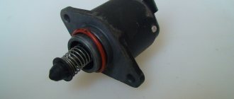
Design features
The valve structurally consists of:
- electric stepper motor;
- four-position rod;
- spring element;
- needles.
When IACs first appeared, they were rotary or solenoid mechanisms. Such devices had two positions - open and closed. This contributed to a decrease in the efficiency of engine speed control. Today, cars use four-step sensors, characterized by the possibility of stepwise feed through the bypass.
The idle air control itself is classified as a consumable item and is therefore considered non-repairable. It can be repaired if it malfunctions, but it will be cheaper to replace it completely.
Where is RXX located?
The device should be located next to the throttle valve and TPS. In some cars, the sensor can be fixed directly to the damper body using varnish. Sometimes the device is mounted using two bolts equipped with special mounting holes. The main thing is that the distance from the needle to the mounting flange on the installed device is 2.3 cm.
Connection diagram
Idle air controller connection diagram
One harness consisting of four cables is connected to the idle speed sensor; it comes from the microprocessor module. As a result of this connection, diagnostics may cause certain difficulties. The car owner will not be able to simply apply voltage to the terminals of the device, since the microprocessor module does this pulsed.
Vehicle electrical malfunctions
The list of faults in the electrical equipment of a car is quite wide. Conventionally, they can be divided into faults of current sources and faults of current consumers. This article discusses malfunctions of current sources.
As you know, the sources of current in a car are the battery and the generator. A malfunction of each current source can immobilize the vehicle at any time.
And if you don’t want to return home on a “tie” or a tow truck, attention must be paid to the technical condition of the battery and generator
In a vehicle's electrical system, the battery and alternator work in tandem. The failure of one leads to the failure of the other. For example, battery malfunctions lead to an increase in the charging current of the generator. Operating the generator in this mode can cause a malfunction of the rectifier unit (diode bridge). On the other hand, a malfunction of the generator voltage regulator is accompanied by an increase in the charging current, which, in turn, leads to systematic recharging of the battery and “boiling off” of the electrolyte.
Battery faults
Battery malfunctions include:
- short circuit between battery electrodes;
- damage to the battery plates;
- cracks in the battery case;
- oxidation of battery terminals.
The main causes of these malfunctions:
- violation of operating rules;
- service life limit;
- manufacturing defects.
Violations of the rules for operating batteries are:
- working with a faulty generator (leads to overcharging or discharging the battery);
- poor contact at the battery terminals (leads to oxidation and destruction of contacts);
- Frequent engine starts or prolonged operation of the starter (leads to deep battery discharge);
- weak fastening of the battery in the engine compartment (leads to mechanical damage to the battery and wires).
The battery can be used effectively for a certain period of time. The average battery life is 3-4 years. With intensive use, as well as operation in harsh climatic conditions, the service life is significantly reduced.
Modern batteries are low-maintenance and maintenance-free. The degree of battery maintenance is determined by the rate of evaporation of water from the electrolyte. For a maintenance-free battery, the critical electrolyte level is reached much later than the end of its service life.
When using rechargeable batteries, you have to deal with manufacturing defects. A faulty battery can be easily replaced under warranty by the seller or manufacturer.
All malfunctions have the same consequence - the battery stops performing its intended function - turning the starter when starting and providing consumers with current when parked. In this case, it is necessary to determine whether the battery needs to be replaced or whether the current source can still serve.
When operating a battery, you must remember that increased discharge at subzero ambient temperatures can lead to freezing of the electrolyte and destruction of the battery case.
Generator faults
The design of a generator is more complex than that of a battery. Therefore, this device has more malfunctions:
- wear of current collecting brushes;
- damage to the voltage regulator;
- damage to the rectifier (diode bridge);
- wear of the commutator (slip rings);
- wear or destruction of the bearing;
- pulley wear or damage;
- short circuit of the stator winding turns;
- damage to the charging circuit wires.
The main causes of these malfunctions:
- violation of operating rules (long-term operation under heavy load, incorrect polarity when connecting the battery, low tension of the generator belt);
- low quality of components;
- exposure to external factors (moisture, salt, high temperature, dirt);
- service life limit.
Wear or destruction of the bearing is accompanied by increased noise when the generator operates. Other generator malfunctions are diagnosed by low charging current. This is indicated by a warning light on the instrument panel, which lights up periodically or constantly in the event of a malfunction.
Diagnostics
Before checking the operation of the controller, perform the following steps:
- The parking brake lever is tightened. Wheel chocks must be placed under the wheels of the vehicle.
- The engine compartment of the car is opened and the negative terminal is disconnected from the battery. To do this, use a key to loosen the fastener on the lock.
- The engine compartment is being inspected. You need to find the idle air control.
- The block with the wire is disconnected from the device.
Manual check
This diagnostic stage is considered the simplest in terms of implementation:
- The block with wires is disconnected from the device.
- Two bolts are unscrewed and the regulator is removed.
- The sensor is connected to the microprocessor unit. The controller must be held in your hands.
- The engine is being started, it is advisable that an assistant do this. At this point, the rod should be pulled into the coil all the way. This occurs as a result of receiving an impulse from the control unit. Then it should move out a short distance.
Manually checking the idle air control valve allows you to determine the functionality of the rod. When performing this, you can make sure that the part does not bend or jam inside the device.
But this verification option does not give a 100% result. It is possible that the modification of the idle speed sensor installed on the vehicle does not match the firmware of the microprocessor unit. The rod extends, but the required amount for its extension is unknown. Therefore, the block and plug are checked, and only the latter is marked.
During a visual inspection, it is necessary to diagnose the integrity of electrical circuits and coils. You should also check the condition of the bypass channel and needle for wear.
User Igor Belov spoke in detail about performing a manual check, as well as other methods of testing the idle air valve.
https://youtube.com/watch?v=zQf1vBy3MeE
Diagnostics with a multimeter
You can check the operation of the controller using the tester like this:
- The connector with the wire is disconnected from the regulator in the engine compartment. If the car is equipped with a 1.6 liter engine, then it is necessary to unscrew the two fastenings of the throttle mechanism to the receiver in advance. Then it moves away from the end of the latter by about 1 cm.
- First, the tester diagnoses the controller's electrical circuit to make sure whether voltage is supplied to it or not. The negative terminal of the multimeter is connected to ground, that is, the body or engine of the car. The positive contact should be connected to pins A and D, they are marked on the connector.
- The ignition is activated and the tester readings are read. The multimeter must first be set to ohmmeter operating mode. The resulting voltage value should be at least 12 volts. If this parameter is lower, then there is a possibility that the problem is a low battery. In the event of a complete lack of power, you must ensure the integrity of the electrical circuit or control unit.
- The ignition is turned off. The next step will be diagnosing the controller itself.
- The multimeter is reconfigured into resistance measurement mode, its terminals are alternately connected to contacts A and B, and then to C and D. The resulting diagnostic value should be about 53 Ohms.
- Then the resistance is measured between pairs A and C, as well as B and D. On them, the working value should tend to infinity. If the values obtained are different, the sensor must be replaced.
Pulse testing on a homemade stand
You can assemble a homemade device without chips; its diagram is shown below:
- The equipment uses 6 volt charging. It can be taken from a mobile phone.
- Connector pads can be purchased at any specialty store.
- During diagnostics, the sensor is first disconnected from the microprocessor module. The rod stroke is checked. If the light indicator of a homemade stand lights up brightly, this indicates that the regulator rod is faulty. If the light is on at half power, then the mechanism is working.
Scheme of a simple homemade diagnostic stand
The price of such equipment is at least 1,500 rubles. Considering the low cost of the idle speed sensor, using a proprietary stand is not economically profitable.
Signs of breakdown
Based on certain signs, it can be determined that the IAC is out of order and needs to be repaired or completely replaced with a new device.
These signs include:
- Floating idle speed;
- Problems with starting the engine; it starts with difficulty even with the gas pedal pressed;
- It is not possible to increase the speed even when the engine has warmed up sufficiently;
- The engine suddenly begins to stall when shifting into neutral;
- The speed decreases when you turn on energy-consuming devices - stove, air conditioner, audio system, headlights, etc.
But replacing the regulator is not always the right decision. In some cases, removing the old sensor and installing a new device in its place will not bring any results. And all because the culprits of the malfunction may be other elements, such as spark plugs or a fuel filter.
Functionality check
If the engine stalls, the speed fluctuates, or turns out to be high, you must definitely check whether the IAC is working.
To check, you will first need to dismantle the fastenings of the throttle assembly, and then carefully move it literally 10 millimeters.
You will need a voltmeter with which you can check whether there is voltage going to the sensor and what its indicators are. In advance, connect the negative terminal from the battery to ground, and connect the voltmeter to the terminals marked with the letters A and D. Next, check the table.
Indications
What do they mean
The voltmeter shows less than 12V
This means that the battery is most likely dead.
There is no data on the meter
The problem should be looked for in the wiring circuit or in the electronic engine control unit
Voltmeter shows 12V or more
Be sure to check the idle air control resistance. There are problems with him. The tester is connected to 4 pins. Normal resistance readings are 50 or 55 ohms
Additionally, do a pairwise check. In this case, the resistance should be infinitely large. If the XX sensor shows different numbers, then the regulator requires mandatory and immediate replacement.
There is another way to check the functionality of the device. To do this, you need to remove the sensor and connect the block. Press the needle with your finger and watch it extend. When the ignition is turned off, the needle should push.
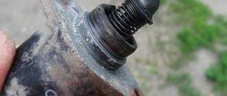
If there is no shock, you can still try to solve the problem by simply cleaning the device. Use a universal and all-powerful product called WD40. Wet the entire mechanism thoroughly with it and, armed with cotton swabs, clean everything you can get to.
When cleaning, pay special attention to the needle and stem
If these measures do not help, there is nothing else left but to replace the IAC.
To replace the XX regulator, you do not have to be a professional. By doing the work yourself, you will gain a rewarding experience and can also save a fair amount of money.
The entire procedure must be carried out in strict sequence, which will allow everything to be done correctly and efficiently. Maybe even better than at a service station.
- Unplug your car. To do this, simply remove the negative terminal from your car's battery. We don't need short circuits or electric shocks.
- Disconnect the connector from the sensor. In the case of an injection engine installed on your VAZ 2110, to disconnect the pad you just need to press the plastic latch.
- Remove the two screws. Moreover, it is better to unscrew the left fastener first, and then the right screw.
Removing the device
- This will allow you to achieve what you want - remove the idle air control. Further operations are simple, like all previous activities.
- Before installing the new sensor in its rightful place, use regular engine oil to treat the O-ring.
- Inspect the condition of this same O-ring. During prolonged use, the seal may become deformed and become cracked. In this case, it is better to replace it with a new one.
- Next comes the calibration stage. You won’t have to make any serious efforts, since the electronic relay will take care of all the main calibration tasks.
- Turn the ignition on for a few minutes and then turn it off.
- If after the operations and calibration the revolutions stop floating, they are not increased and stable, you did everything right, and it was the XX sensor that was to blame.
As you can see, IAC is a fairly important element in the car system, which must be carefully monitored. A pleasant fact is that if troubles arise with the regulator, you can always replace it with your own hands in a matter of minutes.
Resetting ECU Adaptations Using a Chevrolet Explorer
I have already described this process in the section on self-diagnosis of Chevrolet. But let's repeat here too.
What do we need for this:
- Laptop
- Diagnostic adapter
- Diagnostic program, for example, Chevrolet Explorer
How to download, install and configure the program, as well as install the adapter drivers step by step and in detail, is described in the Chevrolet Diagnostics section
We connect the adapter to the diagnostic block and to the laptop
Launch the Chevrolet Explorer program and turn on the ignition.
We connect to the engine control unit, choosing from the list the one that is installed on your car
Attention! Adaptations are reset with the ignition ON and the engine STOP. In some cases, for vehicles equipped with an MR-140/HV-240 ECU, it is necessary to perform “Learn DPKV”. After clicking on the “Learn DPKV” button, instructions with the necessary actions will be displayed on the screen
Go to “Service” – “Service Functions” – “Reset Adaptations”
That's the whole simple process that takes no more than a minute of time.
Video “Self-calibration and removal of the rod from the IAC”
User Ruslan K talked about how to remove the needle from the regulator at home and calibrate it without special equipment.
Do you have any questions? Specialists and readers of the AUTODVIG website will help you ask a question
Was this article helpful?
Thank you for your opinion!
The article was useful. Please share the information with your friends.
Yes (100.00%)
No
X
Please write what is wrong and leave recommendations on the article
Cancel reply
Rate this article: ( 2 votes, average: 5.00 out of 5)
Discuss the article:
Operating principle
In carburetor engines, the problem of enriching the mixture when starting the internal combustion engine was solved by a starting handle and shims. With the advent of electronic ignition, this is done by the idle air regulator in conjunction with other sensors and the computer. Its operating principle is as follows:
- IAC calibration is performed by the ECU controller automatically after detecting this sensor in the system;
- in fact, the IAC is a stepper motor with a conical needle in a special hole in the throttle valve bypass channel;
- The IAC contact does not transmit any signals to the “brain” of the machine, but receives them from the controller, therefore it is not a sensor, but an actuator - an electric valve;
- in turn, the on-board computer “sees” that there is not enough air in the fuel mixture based on the signals from the mass air flow sensor, compared with the signals from the air flow sensor;
- Voltage is applied to the XX regulator, the needle leaves the channel, and the missing amount of air enters the mixture for mixing.
Operating principle of IAC
In addition, the ECU receives signals about the temperature of the coolant and oil in the system. When starting in the cold season, it is necessary to warm up the engine to operating temperature in order to reduce wear on friction parts, so the IAC channel opens slightly to enrich the mixture for the injector, even without the driver pressing the gas pedal.
At the moment of start, the operating algorithm is as follows:
- the key turns, the ignition turns on;
- the rod extends all the way, the needle blocks the bypass channel;
- at the moment the rod rests against the calibration hole, the computer counts the steps backward;
- voltage is applied to the windings, the valve returns to the open position.
The number of reverse steps is programmed in the device firmware. For example, for Basch modifications on a warm internal combustion engine it is 50 steps, January – 120 steps, respectively. In total, the stroke of the rod is divided into 250 steps; the further it extends from the windings of the stepper motor, the greater the number of steps the ECU will count. When purchasing a new IAC, the distance from the mounting flange to the rod needle should be exactly 23 mm.
Injector
Pure gasoline is not suitable for operation of an injection engine, so a throttle valve with an individual sensor of its position at each moment of time is installed at the inlet of the manifold. When starting the engine or stopping the machine with the engine running, the following occurs:
- the computer receives information about the engine shaft speed;
- analyzes how the motor works, that is, clarifies the intended purpose;
- then the readings of the throttle position sensor and the air are compared, that is, the controller “understands” that the damper is closed and a lean mixture enters the cylinders;
- The IAC valve opens, air is supplied bypassing the damper to maintain the speed at the programmed level
In fact, several electronic ignition system devices are involved in the process. If the car stalls or there are symptoms of other malfunctions, diagnostics are performed manually, since this device does not have feedback (self-diagnosis).
In a diesel engine there is no throttle valve, the idle speed regulator is useless, other methods are used to regulate low speeds.
Replacement of IAC on VAZ 2114 was successfully completed
There are situations when, for one reason or another, it is not possible to buy a new regulator. Then there is a need to repair the old device.
Replacing the IAC on a VAZ 2114
The first thing you need to do is try the sensor. To do this, you need to remove it, dip a cotton swab in carburetor cleaner and rinse the contacts. After this, generously lubricate the needle, rod and spring with cleaner. Take a toothbrush and thoroughly clean the greased surfaces. After washing the IAC again, install it in place. It happens that this is enough for the speed to stop “floating”.
A more complex way to repair the device is as follows:
- take the sensor and clean its outer part from dirt;
- remove the three pins that secure the regulator body;
- the case is removed in the most careful manner so as not to damage the contacts;
- if, after removing the case, a break in the solder is detected, then it is necessary to solder the wire to the fastening point and cover this place with a special varnish, this is done to avoid corrosion;
- If gaps are found in the IAC housing, they must be eliminated using sealant to avoid air being sucked in through the valve.
If needle wear or problems with the windings are detected, this sensor must be replaced with a new IAC.
Preparing for replacement: choosing a sensor and the necessary tools
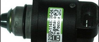
Before you begin replacing the sensor, you need to carry out some preparatory measures. First of all, this is the purchase of a new spare part. You can find quite a lot of sensors on the market that are suitable for the VAZ-2114, but there are two of the most proven and affordable:
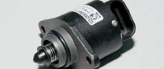
Idle speed sensor
- sensor from K3TA – marking: 2112-1148300-04;
- and a device from OMEGA - marking: 2112-114830.
Important! When choosing, pay attention to the needle rod exit indicator; it should not exceed 23 mm. You will need few tools for replacement. In most cases, it is enough:
In most cases, it is enough:
You will need few tools for replacement. In most cases, it is enough:
- pairs of Phillips screwdrivers of different sizes;
- wrench size “13”;
- any unnecessary rag;
- lubricantsWD-40;
- and cleaner for carburetors or injectors.
Important! Use only clean tools that are in good condition. Otherwise, there is a risk of damaging the edges of the fasteners of some components that are removed during replacement.