Technical description and explanation of error P0507
OBD II trouble code P0507 is defined as "Idle Air Control (IAC) speed higher than expected." Set when the powertrain control module (PCM) is unable to maintain or control engine idle speed.
In most cases, the PCM will attempt to make adjustments to various systems such as fuel timing, ignition timing, injection pulse timing, and others. Trying to maintain a given idle speed. However, when this limit is reached, the PCM will set code P0507 and turn on the warning light.
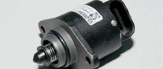
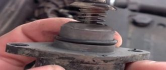
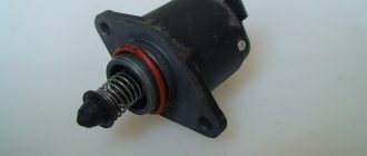
Idle speed in gasoline engines is adjusted and controlled by the idle air control valve, which is usually located on the throttle body. The valve is driven by a stepper motor, which receives commands from the PCM based on information received from various sensors located on the engine.
As long as the throttle valve remains closed, idle speed and quality are controlled by the PCM through the idle air control valve.
For example, if the engine is started in sub-zero temperatures, the PCM commands the valve to allow less air to enter the engine. This allows you to enrich the fuel-air mixture and creates conditions for regulating idle speed in cold weather.
As the engine warms up and combustion becomes easier and more complete. The PCM commands the idle air control valve to increase the amount of air entering the engine in response to changing conditions.
If the load on the engine changes, for example, when some electrical consumers are turned on or off. The PCM adapts the signal voltage to the idle air control valve. To ensure that the idle speed remains stable and at the RPM specified by the manufacturer.
Note that the idle air control valve is closed by the PCM when the throttle valve is opened. This is done in order to prevent excess air from entering the engine.
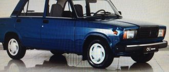
VAZ P0507 High idle speed
Code P0507 is entered if:
there are no fault codes P0102, P010З, P0115, P0117, P0118, P0122, P0123, P0444, P0445, P1509, P1513, P1514; the engine is idling; coolant temperature above 84°C; within 3 seconds, the crankshaft speed of the N10 engine is less than 900 rpm; within 3 seconds, the current correction of the calculated idle air flow IV exceeds 10 kg/h.
If a permanent malfunction occurs, the “CHECK ENGINE” lamp lights up after 2 drive cycles.
The idle speed control is checked using the TDRKH-1 tester (Samara) or J-34730-3 (from UTS. USA).
HOW TO CHECK:
Connect the adapter cable to the diagnostic connector. Start the engine and warm it up to a coolant temperature of 84°C. Using the Errors menu, check whether the fault code is currently active.
Code P0507 is intermittent. If it is currently inactive and there are no other codes, analyze the conditions under which the code occurred.
High idle speed may be caused by a problem that cannot be overcome by the idle speed control. To troubleshoot problems not related to the idle air control, the following checks must be performed.
Over-lean mixture. The idle speed may be low or unstable. Check the fuel supply system for low fuel pressure, water in the fuel or dirty injectors. Check the oxygen sensor for contamination with silicone, glycol or other materials.
Crankcase ventilation system. A malfunction of the crankcase ventilation system can lead to deviations in idle speed. See Map C-7.
Check the system for air leaks. If a malfunction is detected, correct it.
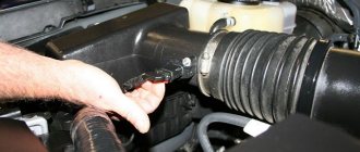
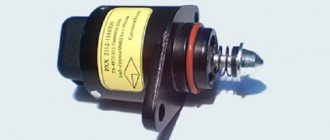
1. Disconnect the harness connector from the regulator. Connect the idle air control tester wires to the battery, then connect its connector to the idle air control control. Start the engine.
Using the tester, control the regulator by setting the idle speed to decrease.
If the idle speed decreases, replace the controller. If they do not decrease, replace the idle speed control.
After repair, start the engine, reset the codes and make sure there is no signal from the “CHECK ENGINE” lamp.
Diagnosis and problem solving
Connect the scanner, read and write down all available codes. This information may be useful if an intermittent fault is later diagnosed.
If other codes are present along with P0507, diagnose and resolve them in the order in which they were stored. The most likely additional codes are usually related to the vacuum system.
Therefore, check the vacuum system for leaks caused by damaged vacuum lines. If necessary, repair and clear all codes before operating the vehicle. Then, retest the system to see if any codes are returned.
Throttle valve
If the code persists, remove the throttle body from the intake tract and inspect it for excessive carbon deposit buildup. In some cases, it may be possible to remove light carbon deposits from the throttle body and auxiliary air passages using approved cleaners.
However, heavy deposits usually cannot be removed without damaging the throttle body or idle air control valve. In these cases, the best option is to replace the throttle body or idle air control valve with original parts.
When installing cleaned or replaced parts, ensure that all seals and gaskets are also replaced to prevent vacuum leaks. Double check all vacuum line connections before starting the engine or operating the vehicle.
Checking wires and connections
If the P0507 code persists, perform a thorough visual inspection of all associated wiring. Look for damaged, burnt, shorted or corroded wires and connectors.
Once no visible damage is found, check resistance, ground, and reference voltage. Compare all readings obtained with the data specified in the manual. Replace wiring as necessary to ensure all readings are within manufacturer specifications.
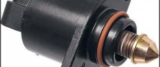
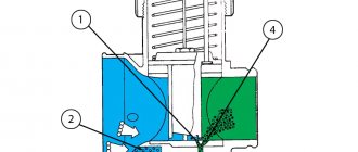
Stepper motor and idle control valve
Check the actual signal voltage that reaches the stepper motor at the connector. Using a scanner, command the idle air control valve to open. Compare the obtained value with the values specified in the manual.
Special diagnostic programs usually produce a voltage range that corresponds to the degree of opening of the idle air valve. And sometimes the degrees of rotation of the stepper motor.
These readings must correspond exactly to the stated values, otherwise the harness must be replaced. If all readings obtained are consistent with the stated values, the stepper motor is faulty and must be replaced.
These steps should solve the problem with error P0507. But if it still appears again, then perhaps the problem is periodic. In such a case, diagnosis can be challenging. And sometimes it is necessary to give the malfunction a chance to worsen in order to understand exactly where the problem is.
How to Troubleshoot or Reset Trouble Code P0507
Some suggested steps to troubleshoot and fix error code P0507:
- Read all data and stored error codes using an OBD-II scanner.
- Clear the codes and check if the P0507 code appears again.
- Observe the engine's operation at idle speed, with the gear engaged and disengaged. To check whether the engine idle speed corresponds to the values specified in the manufacturer's technical documentation.
- Check the engine for vacuum leaks.
- Inspect the throttle body for carbon buildup. And also on the body and inlet of the idle air bypass control valve.
- Disconnect and check the idle air control valve.
- Check if the idle air control valve passages are clogged.
Self-diagnosis
In a car, the operation of the entire electronics system is monitored by a control unit (ECU). In order for the driver to recognize operational failures in time and localize them, cars leave the assembly line with an already built-in diagnostic system. It is located on the front panel. With its help, the system itself detects failures in electronic devices and notifies about them, generating errors with digital codes or their combinations. In this way, the car self-diagnosis occurs. To be able to decipher error codes, special tables have been compiled. In this case, self-diagnosis is carried out on the instrument panel, and not on the computer.
To check, you need to reset the daily mileage data on the wheel revolution meter (odometer), then activate the ignition (position 1).
On all touch devices, the arrows will move twice to the highest readings.
By pressing the odometer button again, messages are received about the installed version of the operating system. The next time you press the button, an indication of problems, if any, is displayed.
What errors may appear during self-diagnosis of the control panel, and how to decipher them
0 - indicates that there are no problems in the electrical wiring, apparently the fault is mechanical;
1 - indicates a malfunction of the ignition system microprocessor;
2 - no signal is detected coming from the circuit leading to the fuel level sensor. Reason: open circuit, plaque formation due to oxidation of contacts or short circuit;
4—signal of increased voltage in the on-board network (more than 16 V). It is necessary to check the battery and generator;
8—opposite signal, the voltage is too low (less than 8 V) due to a low battery or problems with the generator.
If there is not one malfunction, but a group, then an error is displayed on the dashboard, the code of which consists of several digits resulting from the summation of errors. So, for example, the issued error code 10 indicates errors 2 and 8, 6 – the sum of 2 and 4, 12 – 4 and 8, 14 – 2,4 and 8.
12 - a malfunction in the circuit leading to the malfunction indicator lamp, possibly due to damage to the connector contacts or their oxidation, or the indicator itself is faulty;
13 - no data is received from the oxygen concentration sensor device (ƛ-probe). The sensor or the wiring leading to it may be faulty;
14—the coolant temperature in the cooling system is higher than normal. Reasons: sensor failure, low fluid level in the radiator, faulty thermostat;
15 - coolant temperature is below normal. Reasons: a failed thermostat, air entering the system due to a coolant leak;
16 - the voltage in the on-board network is too high;
17 - the voltage in the on-board network is too low;
19 - malfunction in the wiring of the PCV sensor. Reasons: oxidation or contamination of contacts, broken wiring, short circuit, mechanical failure of the wheel;
21-22 - error in the position of the remote sensing sensor, due to a failure of the electronic part, due to a breakdown of the movable core or due to the fact that the coating on the slider has been worn off;
23-25 - deviation from the norm of the intake air temperature sensor. Possible reasons: clogged sensor element, oxidation of contacts, open circuit, short circuit;
24 - the speedometer does not provide reliable data on the vehicle speed. Reasons: the speedometer has mechanical damage, there is contact in the terminal connections, the sensor is faulty, there is a break or a short circuit in the wiring, the computer is malfunctioning;
27-28 - warning about a violation of the level of exhaust gases for one of the reasons: damage to the wiring, the catalytic converter has become unusable, the muffler and muffler suspension are damaged;
33-34 - error code for mass air flow data. Causes: high voltage in the wiring going to the sensor device, interference affecting the impulse from close proximity of wires or sensor to devices with high voltage (generator, ignition wires, etc.), wear of vacuum and air intake hoses;
35 - malfunctions occur when the engine is idling; they can occur due to a malfunction of the hydraulic compensators in the valve mechanism drive, a malfunction of the TPS, or due to unaccounted for air leaks;
41 - pulse error from the camshaft sensor rarely occurs. Cause: damage to the wiring or malfunction of the sensor itself;
42 - malfunction of the ignition system. Reasons: breakdown of the ignition coil or high-voltage electrical wiring, and possibly incorrect spark plug gap setting;
43 - lack of signal from the detonation sensor device. Reasons: sensor failure, contact oxidation or wiring fault;
44-45 - the stoichiometric combustible mixture is incorrectly formed. Causes: incorrect air/fuel ratio, faulty throttle sensor or oxygen sensor;
49 - the on-board computer registers a loss of vacuum for one of the reasons: loss of tightness of the pipeline or working chambers of the amplifier, failure of the check valve;
51 - an error in the operation of the ROM requires checking the connector, injector harness and all wiring, as well as the ground of the control unit;
52 - there is a problem with the operation of the random access memory, it is necessary to diagnose the microprocessor;
53 - there is no signal from the exhaust gas controller;
54 - the octane corrector controller does not respond, it is either de-energized or faulty;
55 - high engine load. Reasons: damage to the power circuit, violation of the cooling mode of the unit, load on the shaft due to worn bearings, sudden changes in voltage in the wiring;
61 - distorted oxygen sensor data. Causes: sensor malfunction, unreliable connection of the contacts of the controller, sensor and ignition system harness or damage to the harness;
Self-diagnosis does not always accurately display breakdowns. The error code can only indicate the section of the electrical wiring where the malfunction occurred. There may also be software glitches that may cause errors to not always be displayed correctly. To obtain more accurate diagnostic data, you should use external devices (diagnostic scanners, computer diagnostics).
error 0507 on VAZ 2114
error 0507 for VAZ 2114 If, when the engine is running warm (coolant temperature is at least 84 degrees C) in idle mode for three seconds, the engine crankshaft speed is above 900 rpm and at the same time the current correction of the calculated air flow is below -10 kg/hour, fault code P0507 (low idle speed) is entered into the controller’s RAM memory. In this case, the controller memory must not contain fault codes P0102, P0103, P0115, P0117, P0118, P0122, P0123, P0444, P0445, P1509, P1513, P1514. If the fault persists within two drive cycles, the Check Engine light will illuminate on the instrument panel.
Checking the operation of the idle air control regulator can only be carried out using diagnostic equipment or a personal computer connected to the diagnostic line of the controller using an adapter. The appearance of fault code P0507 is also possible when the mixture is too lean. To detect and eliminate the malfunction, it is necessary to check the fuel supply system for low pressure and the presence of water in the fuel. Check the oxygen sensor for contamination with silicone or other substances. Check the injectors for contamination. It is also possible that foreign air may leak from under the intake manifold gasket, vacuum brake booster or air pipes, after the mass air flow sensor.
In addition, unstable engine operation may be caused by a malfunction of the crankcase ventilation system. .
ECM error codes for Niva Chevrolet cars and their interpretation
To extract more specific and accurate data about the vehicle's operation, it is recommended to use third-party diagnostic devices or a computer connected via a diagnostic connector.
While control panel error codes can be retrieved using self-diagnosis, ECM error codes are retrieved using external devices.
The received error data is transmitted via the diagnostic connector to an external device in four-digit code format. The task of the external device is to read and decrypt this data.
List of fault codes recorded by the controller
P0102/103 - a low or high pulse is received from the mass air flow sensor, this indicates damage to the circuit or the device itself;
P0112/0113—increased or decreased pulse levels of the intake manifold temperature sensor were received;
P0116 - the pulse from the coolant sensor exceeded the standard values. Reason: failure of the dozh device;
0117/0118—DTOZH warns about too low/high impulse; it is necessary to verify the functionality of the sensor;
P0122/123—receipt of a low or high signal level from the throttle position sensor; sometimes it is enough to clean the mechanical part of the device or check the working condition of the touch device itself; weak/strong signal
P0130-0132—signal transmission error of the oxygen sensor located before the catalytic converter, you can clean the part itself or replace it;
P0133 - there is slow feedback on depletion or enrichment of DC No. 1 to the neutralizer;
0134/0135 – no data from DC No. 1 to the neutralizer. Source of error: there was a violation of the integrity of the wires in the power circuit, unreliable contact, heater DC No. 1 failed;
P0136—open circuit supplying pulse DC No. 2 after the neutralizer. Reasons: short circuit to the electrical wiring that controls the heater, controller malfunction;
P0137/0138 - The signal voltage of the oxygen sensor No. 2, located after the exhaust gas converter, is below or above the permissible range. Reasons: unreliable connection of contacts in the ignition system harness block, sensor and controller, incorrect harness routing;
P0140—no signal is received from DC No. 2 after the neutralizer. Causes: damage to the contacts of the sensor connector or poor-quality connection, open circuit or controller malfunction;
P0141—DC heater No. 2 after the neutralizer is faulty, poor-quality connection in the harness and sensor blocks or DC requires replacement;
P0171/0172 - the code indicates a malfunction of the fuel supply device (exceeds or falls below the lower limit of the permissible range). An error may occur due to damage to the harness, its incorrect route, unreliable grounding of the controller, poor connection of contacts, malfunction of the fuel pump, degradation of the UDC;
P0201-0204—there is a break in the injector control circuit of cylinders 1-4;
P0217 – the permissible engine temperature has been exceeded. Source of error: thermostat malfunction, low coolant level, fan not working, poor connector contact or faulty relay, short to ground in the voltage supply wiring or its break;
P0261/0264/0267/0270—a short to ground control circuit was detected in the cylinder injector (1,2,3, 4). Malfunctions may include an open circuit, short to ground or power supply of the injector control circuits, a malfunction of the controller or ignition system harness;
P0262/0265/0268/0271—Short circuit of the electrical control circuit to the on-board network of cylinder injectors (1,2,3,4). Reasons: turn-to-turn short circuit in the corresponding injector, controller malfunction;
P0300—the system has detected misfires that affect toxicity, it is necessary to check the fastening of the ground terminals in the ignition system harness, the absence of mechanical damage to the pistons, valves, camshaft, the integrity of the vacuum hoses and their connections;
P0301/03102/0303/0304—in cylinders 1-4, the fuel-air mixture ignites partially or does not ignite at all. Reasons: malfunction of ignition and fuel supply system elements, air leaks in the intake system after the mass air flow sensor, unreliable connection of vacuum hoses, mechanical failure of engine parts, radial runout of the disk;
P0327/0328—deviation of the knock sensor signal from the permissible threshold to the lower or upper part. Reasons: sensor malfunction, wiring damage, failure of engine parts;
P0335-00328—The absence of a pulse from the DPKV occurs even if there is a signal from the crankshaft position sensor. Causes: damage to the teeth on the crankshaft pulley drive disk, damage to the electrical wiring, short to ground, broken contacts of the DPKV block;
P0340—Phase sensor circuit malfunction. Source of error: breakdown of the controller, sensor, damage to the harness or pad locks;
“Camshaft position sensor is faulty (Phase sensor error).”
P0342/0343—low or high level of the DPRV pulse.
P0422—the efficiency of the converter is reduced, the controller detects an increased oxygen content after the converter. Possible reasons: the wrong type of neutralizer is installed; presence of metal-containing additives in fuel; leakage of the exhaust system between the exhaust pipe and the converter, the converter and the main muffler;
P0441/0443—error in the flow rate through the canister purge valve. The causes of the error may be: jamming of the canister purge valve, squeezing, clogging or incorrect connection of the hoses between the canister and the engine, vacuum leak in the fuel vapor recovery system;
P0480/0481 - open circuit in the control wiring of fan relay No. 1/2 of the cooling system, short to ground or short to ground. Source of error: faulty harness, controller or fan;
P0500/0503—there is no pulse from the speed sensor. Reasons: violation of the integrity of the harness, possible breakdown of the sensor or controller;
0506/507 – blocking of the XX regulator due to low/high XX speed;
P0560—voltage drop in on-board systems due to battery discharge;
P0562/0563—the controller's on-board power supply voltage is below 10V, or above 17V. It is necessary to check the battery, generator relay and the integrity of the wiring harnesses;
P0615—no load in the starter relay control circuit. The fuse and wiring need to be checked;
P0616 - short to ground in the additional starter relay circuit. The cause of the code may be an incorrect connection of the alarm system;
P0617—short to +12V in the starter relay control circuit.
P1135 - malfunction or interruption in the circuit of the heater DC No. 1 to the neutralizer. Source of error: short to ground or +12V, lack of load in the circuit, installation of a different type of sensor;
P1140—difference between the data obtained from the mass air flow sensor by measurement from the calculated value by the threshold value. Reasons: failure of the controller, poor contact in the controller and sensor block, installation of intake system parts that does not comply with the ECM;
P1141—a malfunction was detected in the DC heater circuit after the neutralizer. Source of error: installation of the wrong sensor, open circuit;
P1386—the permissible limits of test pulses coming from the mixture detonation channel length sensor have been violated. If the error occurs again after clearing the error codes, the controller must be replaced;
P1410—the purge valve control line has a short to the source of the on-board control circuit network;
P1425—short to ground in the canister purge valve control circuit;
P1426— there was a break in the control line for the canister purge valve;
P1501/1502—short to ground or to +12V in the power and control lines of the main fuel pump;
P1509—XX regulator circuit overload. Cause: electrical wiring fault;
P1513/1514—short to ground or +12V in the IAC control circuit;
P1541—no load in the fuel pump relay circuit. Reasons: incorrect alarm connection, open circuit;
P1570—No positive response from immobilizer. Reason: the immobilizer unit may have become unusable;
P1602—data from the RAM about a loss of voltage in the on-board circuit disappears in the controller. Reasons: malfunction of the power supply circuit from the battery to the controller;
P1606—incorrect signal detected from rough road sensor. Reasons: sensor failure, defective wiring harness, unreliable connection of contacts in the sensor block;
P1640—Electrically reprogrammable memory read or write test error;
P1689—violations have occurred in the controller error memory; the controller needs to be replaced.
2188 - a frequently occurring error warning of an excessively rich fuel mixture at idle; the contacts of the injection system harness pads, sensor and controller are not reliably connected.