Good day! Since the engine won’t start and I have nothing else to blame, I decided to check the timing belt and valve marks, although the “master” who bored and assembled the engine for me swore that he assembled everything correctly. In general, I began disassembling, removed the valve cover, cranked the crankshaft, and yet it turned out that that same “master” had somehow placed a mark on the camshaft not at TDC, but at BDC. Now it became clear to me why the car wouldn’t start) Well, then I’ll tell you everything as a manual...
And so what we need for this whole procedure: 1. Special. a wrench for cranking the crankshaft (personally, I didn’t have one, so I just turned it with a 24 wrench)
2. Keys for 10, 13 and 17 3. Crowbar 4. Screwdriver 5. Feeler gauge 0.15 for adjusting valves (and it is better to take a special wide one, rather than a set of narrow ones)
First, remove the valve cover by unscrewing all the nuts by 10.
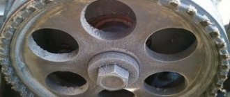
Then we rotate the crankshaft to TDC so that the mark on the pulley coincides with the long mark on the block.
When combining these two marks, the mark on the sprocket should also coincide with the ebb on the camshaft bed (if the mark is at the bottom, then rotate the crankshaft 360*)
If the marks do not match, as was the case for me, do the following: 1. Turn the crankshaft so much that the marks on the sprocket and the ebb match. 2. On the left side of the block, first leave the tensioner with a 13 key, and then unscrew the 2 nuts with a 10 and pull out the tensioner itself.
3. Unscrew the bolt securing the sprocket to the camshaft with a 17mm wrench (the main thing is not to drop the bolt into the engine)
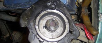
4.Remove the star and, holding the chain with your hand, remove the star from the chain. 5.Holding the chain with your hand, we begin to rotate the crankshaft until the mark on the pulley and the long mark on the block coincide. 6.Then we insert the sprocket into the chain and install the chain tensioner in place, tightening only the nuts by 10. 7. From the inside of the chain, we begin to press the crowbar through the chain onto the shoe (the shoe in the photo below is what the tensioner rests on), so that tension the chain and at the same time try to put the sprocket on the shaft.
8.After putting on the star, screw it on and tighten the tensioner with a 13 key.
This completes the procedure for setting timing marks.
Now, without turning the crankshaft, leaving all marks in the matching position, we begin to adjust the valves. First, we adjust valves 6 and 8 (the valves are counted from the radiator) Then, having adjusted them, we turn the crankshaft 180* and adjust 4 and 7. Then, turning the crankshaft another 180* (in total, 360*), we adjust 1 and 3. Then we turn it another 180* (in general, already 540 *) and adjust 2 and 5.
The adjustment is made as follows: Loosen the lower nut with a 17 wrench, then insert the feeler gauge and turn the upper nut with a 13 wrench to adjust the gap (tighten it, increase it, unscrew it, decrease it). The probe should not go through tightly, but with very little resistance.
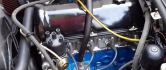
Having adjusted the valves, return the crankshaft and camshaft to the position where all marks coincide (4th cylinder at TDC) and now set the ignition. In this position of the crankshaft and camshaft, the slider on the distributor should point exactly to wire 4 on the distributor cap, or to the spark plug of the first cylinder. If this is not the case for you, then unscrew the nut 13 at the base of the distributor, lift it and turn it to the desired position. Then we put everything back together in reverse order.
All! This completes the procedure for all adjustments. Next, we start the engine and set the angle of the KSZ either by ear or with a control. Since I have BSDS, I did not do this.
Thanks everyone for reading. I hope this information helps someone. Good luck to you!
Setting the ignition on a VAZ 2107 is easier than it seems. This does not require any special skills or tools. The article describes the complete procedure.
Installing the ignition on a VAZ 2107 is not so difficult. But in this matter you need to be extremely careful and precise, otherwise the whole procedure will have to be repeated.
Injector
The VAZ 2107 was produced with two types of engines - injection and carburetor. Modifications with a fuel injection unit have a special design and electronic ignition control is not required. The adjustment occurs automatically: the ECU uses sensors to determine the ignition timing and all other details. The participation of car owners in this procedure is limited to aligning the timing chain or belt using marks.
If problems arise with the electronic ignition of a Lada 2107 on an injection engine, it is necessary to flush the injector and replace the failed components.
Adjusting the ignition on the VAZ 2107 injector.
About their device
Before finding out the importance of the elements of the ignition system in question, it is necessary to understand their structure. Structurally, the high-voltage wire consists of the following parts:
Each element performs corresponding tasks, and at the slightest violation of integrity, it will be necessary to replace it. Armored wires cannot be repaired, since they play one of the main roles in the car’s ignition system, and also belong to the category of consumables.
This is interesting! Few people know that on a car it is necessary to change not only the spark plugs, but also the armored wires, which wear out over time and begin to malfunction.
On a distributor or MZ
It is a mistaken opinion that armored wires on a machine are ordinary wires that are designed to transmit current from a source to a receiver. As you know, VAZ 2107 cars were produced in two variations of the fuel supply system - carburetor and injector. Although many parts and mechanisms on the carburetor and injector are the same, this does not apply to the GDP. The carburetor VVP differs from the injection one on the VAZ 2107 in the following parameters:
Knowing the design differences, you must also understand that high voltage flows through the wire. The current comes from the distributor or MG through the wires to the spark plugs. The slightest malfunctions lead to the fact that current is not supplied to the spark plug, and a spark does not occur. If a spark does not occur, the cylinder does not work, which negatively affects the operation of the engine.
Ignition check
The ignition is controlled by controlling the distance between the switch contacts.
All VAZ cars have a common backlash indicator of 0.3 to 0.4 mm.
To measure the gap you need to use a special feeler gauge. If the measurement results do not meet the standards, it is necessary to loosen the adjusting screw and correct the gap.
It is also necessary to check the condition of the contacts and clean them. The contact group must be replaced if there are signs of wear.
Adjusting the gap of the VAZ 2107 distributor breaker
The quality of the spark depends on the distance between the switch contacts and the condition of the contacts themselves. To adjust the VAZ 2107 distributor, you need to do the following:
- tighten the fixing screw;
- loosen the screw securing the switch contacts;
- disconnect the mounting brackets and remove the distributor cap;
- unscrew the screws securing the slider;
- install and secure the slider;
- Clean the switch contacts with sandpaper (to avoid damaging the contacts, you must use sandpaper with a grit size of no more than 600).
- turn the adjusting screw to set the gap to 0.4mm using a suitable thickness gauge;
- secure the dispenser lid.
- remove cursor;
In addition to adjustment, repair of the VAZ 2107 distributor may be required. This consists of cleaning the contacts on the distributor cover or replacing the cover itself, replacing the slider, resistor or contact group.
US Postal Service » May 15, 2009, 01:31 pm
During the overhaul of the internal combustion engine, the chain with stars was changed. The timing belt was set according to marks: respectively on the crankshaft pulley, tooth and sprocket of the timing chain. But there was such garbage - put a mark on the bottom - you definitely won’t put the one at the top - it comes out a little to the right or to the left, but if you throw it over the tooth, it turns out to be quite good. How is this actually done correctly?
At first I thought that the ignition timing was definitely set on the computer - I went to the service station for diagnostics - they told me that the computer was supposedly flashed and they couldn’t configure anything using the tag - maybe Zizdat or they don’t know each other? As far as I remember, on the 409 engine it was controlled by the ECU
Carburetor
There are a large number of strobe lights on the market, but in general their operating principle is equally suitable for ignition installations. The price only affects the service life of this device. The strobe light operates while the engine is idling. The ignition is adjusted by aligning the marks on the crankshaft pulley with the scale on the timing cover. The matching of signs is assessed using a stroboscopic light beam.
When using a VAZ 2107 with 92 or 95 gasoline, the average mark of the scale should coincide with the pulley mark. In case of deviation, the ignition angle must be adjusted by turning the distributor housing. When turning the distributor clockwise, the advance angle increases, and when moving in the opposite direction, it decreases.
Adjusting the ignition by ear
On Lada 2107 you can also adjust the ignition according to gas. This is a cruder method, but the advantage is that no additional equipment is required. Before starting, it is necessary to warm up the Semerka engine. Then drive on a straight and level road. When reaching a speed of 60 km/h, you must press the accelerator pedal sharply.
Using detonation, you can determine the correct ignition setting. When weak and rapid detonation occurs, the ignition point is considered to be within normal limits.
A strong knock indicates that the ignition is too early. In this case, turn the knob clockwise.
No hit means late combustion. In such a situation, turn the distributor counterclockwise.
If the ignition is set incorrectly, various breakdowns will occur, increased detonation, wear of the gas distribution mechanism and a decrease in engine power, as well as increased vibration and increased noise. Gasoline will not ignite immediately, detonation will occur, hitting the cylinder walls, causing vibrations. The figure below shows the combustion chamber at the moment of top dead center of the VAZ 2107 engine; at the moment the operating pressure is created, the valve reliably closes the chamber. 1 – normal combustion, 2 – detonation of the mixture.
What to do before setting the ignition
First you need to make sure that:
- all spark plugs work, the gaps are adjustable, there is no soot, the top is a spark plug with soot, the bottom is normal.
- clean the coil, distributor cap and distributor contacts from dirt and dust;
- the contact and quality of the wire from the coil are good, the ignition coil is working;
- reinforced wires have good insulation, contact with candles;
- check the distributor contacts to see if they are burnt out. If they are burnt out, they must be replaced;
- Ignition adjustment should be made with the engine fully warmed up.
How to set the ignition to a light bulb?
- unscrew the spark plug of the first cylinder;
- insert a rubber plug of a suitable size into the hole of the spark plug so that it fits tighter;
- then slowly turn the crankshaft with a wrench until the plug comes out. This will mean that the piston of the first cylinder is at or very close to top dead center;
- then we align the central mark on the front engine cover and the mark on the crankshaft pulley. The central mark indicates the ignition timing angle of 5°;
- then screw the candle back on and put a thread on it;
- prepare a 12 V light bulb with wires, one wire to the positive of the ignition coils, and the second to ground;
- loosen the distributor fastening nut and determine the ignition timing;
- turn on the car ignition, the light should turn on;
- turn the distributor clockwise until the light goes out;
- now turn the vending machine counterclockwise until the light comes on again. This is a precise adjustment when the ignition timing is correctly set;
- tighten the distributor nut.
The main components of the distributor and a description of its operation
Device.
A capacitor is secured to the bottom of the housing with screws. A drive roller is installed on bushings in the center of the housing. Its bottom has splines with which it engages with the drive gear. In the upper part of the roller there are contact drive cams (for contact ignition) or a steel cup with four slots - a screen (for contactless ignition).
At the very top, on a steel platform, two weights and two springs of the centrifugal ignition regulator are installed. A plastic housing with a moving contact and noise suppression resistance of the high voltage distributor (slider) is screwed onto the top with two screws.
The entire structure is closed with a lid on two spring latches. The body and cover have a tongue and groove so that they fit together in only one position. The cover contains contact terminals for high voltage wires from the spark plugs and from the ignition coil.
Job.
The distributor is connected through the drive to the engine crankshaft and rotates with it. For two full revolutions of the crankshaft, the distributor shaft makes one revolution. This is due to the fact that our engine is four-stroke. When installing the distributor in place, the roller is oriented in strict accordance with the operating order of the engine.
Its weights, under the influence of centrifugal force, which is greater the higher the engine speed, diverge to the sides and move the cams relative to the roller, making ignition “earlier.” When the engine speed decreases, the springs return the weights to their place and the ignition becomes “later”.
This is necessary to increase engine power and efficiency. In addition to the centrifugal one, a vacuum ignition timing regulator is also installed on the distributor. Its function is to fire “earlier” at low throttle opening angles and “later” at sharp throttle opening angles.
Preparatory stage
To set up the ignition on a VAZ 2107, no special conditions are required; the operation can be carried out both in the garage and on the street, even in winter. For work, prepare the following set of tools:
- a key with a long handle for turning the crankshaft;
- 13mm wrench;
- flat screwdriver;
- metal probe 0.35 mm thick;
- key for unscrewing spark plugs.
- 12V car light bulb with soldered wires;
Ignition adjustment tool
Note. Instead of a special wrench, you can use a regular 36 mm open-end wrench to turn the crankshaft. If you don’t even have such a key, you will have to set the marks in the old proven way: engage 4th gear and lift the rear wheel, turn it manually, thereby turning the crankshaft.
Ideally, it is best to have in your arsenal a device for setting the ignition on a running engine - a strobe. It is equipped with a warning light that simultaneously flashes at the moment of spark in the cylinder, which allows you to see the position of the notch on the crankshaft pulley at idle and clearly adjust the angle of attack.
This is what a strobe looks like, which is convenient for adjusting the ignition timing
Important point. The ignition is adjusted to ensure that the spark appears in a timely manner and the engine starts, after which further adjustments will be required. But the latter will not bring the desired result when there is no compression in the cylinders or there are problems with the carburetor. If these faults are not corrected, the engine will remain unstable regardless of how the ignition system is configured.
Hence the conclusion: you can set the ignition correctly at any time, but it can be adjusted well only on a working engine and carburetor.
Knock sensor
The knock sensor (DS) is designed to save fuel and increase engine power. It consists of a piezoelectric element that generates electricity when detonation occurs, thereby regulating its level. As the oscillation frequency increases, the voltage supplied to the electronic control unit increases. The DD adjusts the ignition settings to optimize the ignition process in the cylinders of the fuel-air mixture.
Knock sensor location
On VAZ cars, the DD is located on the power unit block between the second and third cylinders. It is installed only on engines with a contactless ignition system and control unit. On VAZ models with contact ignition there is no DD.
The knock sensor is located on the engine block between the second and third cylinders
Signs of a malfunctioning knock sensor
A malfunction of the knock sensor manifests itself as follows.
- Acceleration dynamics deteriorate.
- The engine "troits" at idle.
- During acceleration and at the beginning of movement, the CHECK indicator lights up on the instrument panel.
If any of these symptoms occur, a DD check will be required.
Checking the knock sensor
DD is checked using a multimeter. First you need to check whether the value of its resistance corresponds to the values regulated by the manufacturer. If the values differ, replace the DD. The check can be performed in another way. For this:
- Set the multimeter to voltmeter mode in the “mV” range and connect the probes to the sensor contacts.
- They hit the DD body with a hard object and look at the readings of the device, which, depending on the force of the blow, should vary from 20 to 40 mV.
- If the DD does not respond to such actions, it is replaced with a new one.
Video: checking the knock sensor
How to set the ignition on a VAZ 2107
The ignition module is a mechanism whose malfunctions are very difficult to identify. Problems usually begin to be resolved when it becomes obvious that something is wrong with the car. If your VAZ 2107 does not start the first time, you cannot set the ignition and the erratic operation of the engine begins to confuse you - it’s time to carry out a proper check. Let us remind you that the “injector” type engine ignition module is the same system that, using coils, supplies electricity to generate a spark and start the car.
Preparing for work
If you decide to make sure that the ignition module is working and each coil is working, you need to use a special device called a multimeter or, in other words, an ohmmeter. It will show what voltage the ignition module emits and will help determine the location of current leakage in the circuit.
For your convenience, before starting the process, it is better to place the form outside - this will make such painstaking work easier and will not tire you.
Proper short circuit check
First, let's check the coil winding for a short circuit. To do this, you need to connect a multimeter that determines the resistance. Before checking, it is recommended to lubricate the tip of the high-voltage wire with a special lubricant, which can be purchased at any VAZ 2107 spare parts store, or with technical petroleum jelly.
We disconnect the module from the tips and connect one terminal of the device to the central contact on which the coil is located, and the other to the ground. If the device display shows “infinity,” it means there is no short circuit, that is, everything is in order. It is worth noting that if after playing the circuit the display indicators have not changed (and, for example, the number one remains), then this is infinity.
Now let's check the primary ignition circuit for an open circuit.
To do this, you will need to install a multimeter on the left and right contacts responsible for the ignition function. With this setting, the ohmmeter should change its reading. Otherwise, not just the coil, but the entire device will be replaced. Please note that the speed is 3-3.5 ohms.
Checking the secondary windings of the module
First we disconnect the ends of the thread from it. If you have already done this, place it directly in front of you. Next, install the device on the top and bottom right outputs and carefully check the indicators that the device will set in a second.
Next, we perform exactly the same actions with the upper and lower left outputs. Of course, the ohmmeter reading should change and ideally it should be at least 7 ohms.
If at least one coil does not meet the standards, in order to avoid unforeseen situations with your VAZ 2107, we recommend replacing the entire module.
How to remove the coil
If your fears are confirmed and the coil really needs to be replaced, installing a new one will not be difficult.
To do this, first remove the air filter housing, then the negative terminal from the battery and disconnect the high-voltage wires from the module. Having pulled out the wires that are located there from the module cover, unscrew the three nuts that secure it and disconnect it from the bracket.
that's all. Even a novice VAZ 2107 driver can carry out such simple manipulations. If you already have a new part, you can install it immediately after removing the coil. To do this, you need to perform all the steps we previously described in reverse order.
If you happen to forget how the high-voltage cables were originally laid, then with a little help from an attentive manufacturer you won't have to fiddle around for long. The secret is that the module itself shows the numbers of the cylinders to which the wires need to be connected.
Setting the ignition
Another serious problem for VAZ 2107 owners who have an injection system is how to accurately set the ignition.
As you know, in such models all engine control is carried out electronically, so for such work you will need a computer, installation of a special program for the engine of an injection car, a tester, as well as wrenches and screwdrivers.
First of all, turn on the ignition and ground to make sure the electric pump is working properly. If it doesn't work, check the relay that controls it.
Is the fault indicator flashing? Connect a personal laptop with a special program to the car’s on-board computer to try to determine the cause using the available data.
If the engine is running properly, start the engine and check the throttle assembly: throttle position sensor, throttle opening level (no more than 1%) and passing cables. Use a tester to measure the voltage on the sensor (it should not exceed 0.55 volts) and in the on-board network (its voltage should exceed 12 volts).
Repeat the same steps again, but with the accelerator pedal depressed. All readings should now change as the sensor voltage is usually around 4-4.5 volts and the throttle opening is hovering around 90%. Adjust the throttle to full open and turn off the auxiliary air flow, then start the engine and keep the shock absorber half-open. Now you need to adjust the throttle valve to completely close the hole.
As you can see, there is nothing difficult either in installing the coil yourself or in setting up the ignition on this car model. Now you can decide for yourself whether to contact specialists or not. Remember that by timely carrying out small checks and minor repairs of the VAZ 2107, you will always be confident in the reliability of your “iron horse”.
Installing the "Start" button
Some car enthusiasts install a separate button in the car in a convenient place to start the engine. It is connected to the starter circuit by breaking the red wire going to terminal 50 on the ignition switch. The car is started as follows:
In this case, you can turn off the engine only by turning the key in the opposite direction.
In order to use a button to stop the motor, that is, to turn it into a “Start-Stop” button, you need to use two additional relays:
When you press the button, current from the battery goes to the headlight relay, closing its contacts, and then to the starter. When the engine starts, the button is released, opening the contacts of the starter relay and breaking its circuit. However, the positive wire remains connected through the headlight relay for some time. When you press the button again, the headlight relay contacts open, breaking the ignition circuit, and the engine stops. To delay the activation of the starter, an additional transistor is included in the circuit.
Thus, even a novice car enthusiast can replace the ignition switch of a VAZ 2107. To do this, you need a minimum set of tools and following the recommendations of specialists
Particular attention should be paid to the correct connection of wires to the lock contacts
Source
Diagnostics of malfunctions of the ignition module of injection VAZ 2107
The injection ignition of the VAZ 2107 is completely electronic and is considered quite reliable. However, there may be problems with this. The module plays an important role in this.
Signs of a malfunctioning ignition module
Symptoms of a faulty module include:
- change in sound and color of exhaust;
- engine interference;
- the Check Engine warning light on the dashboard lights up;
- floating minimum;
- increased fuel consumption.
- dips and jerks during acceleration;
However, these signals may appear due to other malfunctions, for example, a malfunction of the fuel system, as well as the failure of some sensors (oxygen, mass air flow, detonation, crankshaft position, etc.). If the engine starts to operate incorrectly, the electronic controller puts it into emergency mode, using all available resources. Therefore, when the engine operation changes, fuel consumption increases.
In such cases, you should first of all pay attention to the controller, read the information from it and decipher the error code that occurred. To do this, you will need a special electronic tester, which is available at almost all gas stations. If the ignition module fails, error codes in engine operation may be as follows:
- P 0352 – break in the winding or windings of the coil responsible for 2-3 cylinders.
- P 0351 – break in the winding or windings of the coil responsible for cylinders 1-4;
- P 3000 - no spark in the cylinders (for each of the cylinders the code may resemble P 3001, P 3002, P 3003, P 3004);
Repair
Ignition module VAZ 2107
The design of the ignition module is quite complex: it includes one or more coils, a board, contacts and wires. Of all the above elements, only contact connections can be repaired; in some cases, replacement of parts (transistors, coils) is possible.
The module is dismantled and opened for repair purposes. For this you will need:
- Socket wrenches with heads 1, 13 and 17.
- Hexagon 5.
- Screwdriver.
- Soldering iron.
- Flux for aluminum.
- Stranded wire.
- Nail polish.
Opening the ignition module
Repair of the ignition module is carried out in the following order:
- On the removed device, open the case by prying it off with a screwdriver.
- Remove the silicone film covering the board.
- All aluminum is removed from the explosive contacts.
- On the board, new wires are soldered in place of all the dismantled old ones. To do this, the surface of the collector is cleaned of deposits, after which the board is heated to 180°C (a characteristic smell will indicate when the desired temperature has been reached). During the soldering process, the ends of the wires are connected to the module.
- At the end of the operation, all contacts, the board and the module are covered with nail polish.
- The device is assembled in the reverse order, installed on the car and the engine is started. In case of normal operation, the ignition module is sealed tightly with sealant, while the wires are tucked inside the cavity so that they are not pinched at the edges by the plate.
If the device does not work, then a breakdown inside the module should be looked for more carefully. The transistor, electronic component may have failed, or there may be a break in the coil. Such a repair makes sense only if its price is significantly lower than the cost of a new part.
Checking the module and adjusting the ignition of the VAZ 2107 (injector)
The VAZ 2107 ignition module (injector) is a unit whose malfunctions are quite difficult to diagnose. Problems in the operation of the module are paid attention to only after serious malfunctions occur in the engine. If the engine does not start, you should try adjusting the ignition. If the engine runs unevenly, a serious check of the functionality of the VAZ 2107 ignition module may be required.
The ignition is an electronic system that converts the low voltage of the vehicle's electrical system into high voltage and supplies the latter to the spark plug electrodes.
Checking the ignition system elements
Engine surges, especially in the rain, are the result of damaged insulation of high-voltage cables. The insulation of the wires must not have cracks or damage. You can check the insulation for damage using a wire connected to ground. If you pass it over the insulation while the engine is running, a spark will be observed in areas with damaged insulation. Another telltale sign of poor insulation is an obvious electric shock when touching high-voltage wires while the engine is running.
A broken high-voltage wire can be easily determined using an ohmmeter. The resistance should be between 3-10 kOhm. The spread of indicators between the wires should not be more than 1-2 kOhm.
Signs of breakdown
When the ignition is turned on, the ECU malfunction indicator light comes on and should go out after the engine starts. A burning light is the first sign of problems with the ignition system. Other prerequisites for diagnosing the ignition module are fluctuations in engine speed and starting problems. The cause of such failures may be faulty high-voltage cables or spark plugs, so before starting the ignition diagnostics of the VAZ 2107 (injector), you need to make sure that they are in good condition. Cylinder misfires are often caused by compression problems or a damaged intake manifold gasket. This must be taken into account when searching for the causes of engine failure.
Preparing for ignition diagnostics
To check the condition of the elements of the ignition system and the module as a whole, you will need a multimeter - a device designed to measure the electrical characteristics of the system (resistance, voltage, current). It can be used to determine the voltage supplied by the module to the ignition coil, the condition of the coil, and the reasons for the loss of current in the circuit. For ease of use, the ignition module can be removed.
Removing the ignition module VAZ 2107
- Remove the air filter housing.
- Disconnect the negative terminal from the battery.
- Disconnect the high voltage cables from the ignition module cover.
- We unscrew the three nuts securing the VAZ 2107 ignition module and disconnect it from the bracket.
Checking the ignition coil
The coil is checked for two indicators: the presence of a short circuit and a break. Before diagnosing, disconnect the ignition coil. Next, one probe of the device is connected to the central contact of the coil, the second - to the body (ground). If the display shows resistance to infinity, there is no short circuit.
The primary winding of the coil for an open circuit occurs differently. The probes of the device must be connected to the left and right contacts. The resistance between them should be within 3-3.5 Ohms.
If the resistance values of the primary winding are not normal or there is a short circuit in the coil to the housing, it must be replaced.
Ignition adjustment
Replacing a VAZ 2107 injector does not require adjusting the ignition timing. The electronic control unit uses a sensor to independently determine the optimal ignition timing. The participation of the car owner in setting up the operation is limited to synchronizing the engine using tags.
To check the functionality of the ECU and the functionality of the sensors, you need to connect a computer with specialized software. In this way, the cause of most malfunctions in the electronic ignition system can be determined.
It is also worth checking the operation of the throttle position sensor yourself. When the throttle valve is closed, the voltage on the sensor should not exceed 0.55 volts, and when fully open - 4.5 volts. Measurements should be made with a voltmeter with the ignition on.
High voltage wires
High voltage wires (HVW) transmit impulses from the coil to the spark plugs. Unlike other wires, they must not only withstand high voltage, but also protect other parts of the car from it. Each wire consists of a conductor with a metal tip, rubber caps on both sides and insulation. The serviceability and reliability of the insulation is of great importance, since it:
- prevents moisture from entering the conductive element;
- reduces current leakage to a minimum.
Malfunctions of high-voltage wires
The following main malfunctions are characteristic of GDP:
- breakage of the conductive element;
- voltage leakage due to poor insulation;
- excessively high wire resistance;
- unreliable contact between the GDP and the spark plugs or its absence.
If the VV is damaged, the electrical contact is lost and a discharge occurs, leading to voltage loss. In this case, the spark plug receives not the rated voltage, but an electromagnetic pulse. Faulty wires lead to improper functioning of some sensors and interruptions in the operation of the power unit. As a result, one of the cylinders stops performing useful work and runs idle. The power unit loses power and begins to detonate. In this case, they say that the engine is “troubling.”
One of the malfunctions of high-voltage wires is a break
Diagnostics of high-voltage wires
If you suspect a malfunction of the engine (the engine is “troubling”), they must first be carefully inspected - damage to the insulation, chips, or contact with hot engine elements is possible. Particular attention should be paid to the wire contacts - there should be no traces of oxidation or soot on them. If no visible damage is found, proceed to detect a possible break and measure the resistance of the GDP using a multimeter. The wire resistance should be 3–10 kOhm. If it is zero, the wire is broken. It should also be taken into account that the resistance should not deviate from the norm by more than 2–3 kOhm. Otherwise, the wire should be replaced.
Selection of high voltage wires
When purchasing new wires, you should pay attention to the car manufacturer's recommendations. The VAZ 2107 is usually equipped with VPPV-40 (blue) wires with distributed resistance (2550 +/-200 Ohm/m) or PVVP-8 (red) with distributed resistance (2000 +/-200 Ohm/m). An important indicator of GDP is the permissible voltage. If the actual voltage values exceed the permissible values, breakdown of the cable insulating layer may occur and the wire may fail. The voltage in a non-contact SZ reaches 20 kV, and the breakdown voltage is 50 kV.
The material from which the GDPs are made is also important. Typically the wire has polyethylene insulation in a polyvinyl chloride sheath. Silicone GDPs are considered the most reliable. They do not become rough in the cold, which prevents them from loosening in their nests, and are less prone to breakdowns. Wire manufacturers include Champion, Tesla, Horse, and others.
Tesla products are considered one of the most reliable
Ignition module
The ignition module is a device designed to convert DC voltage from the on-board network into high-voltage electronic pulses with their subsequent distribution between the cylinders in a certain order.
Design and operating principle
The design of the device includes two dual output ignition coils (transformers) and two high-voltage switches. The voltage supply to the primary windings of the transformer is controlled by the controller based on information received from the sensors.
In the ignition system of an injection engine, voltage distribution is carried out according to the principle of a spark at idle, which ensures a pairwise separation of the cylinders (1-4 and 2-3). A spark is generated simultaneously in two cylinders: in the cylinder where the compression stroke ends (power spark), and in the cylinder where the exhaust stroke begins (idle spark). In the first cylinder, the air-fuel mixture ignites, but in the fourth, where gases are exhausted, nothing happens. After starting the crankshaft half a turn (180 0), the second pair of cylinders is included in the process. Since the controller receives information about the exact position of the crankshaft from a special sensor, there are no problems with sparks and their order.
Location of the ignition module VAZ 2107
The ignition module is located on the front of the cylinder block above the oil filter. It is secured to a specially provided metal bracket with four screws. This can be determined by the high-voltage wires coming out of the housing.
Factory designations and characteristics
VAZ 2107 ignition modules have catalog number 2111-3705010. Alternatively, consider product numbers 2112-3705010, 55.3705, 042.3705, 46.01. 3705, 21.12370-5010. They all have approximately the same characteristics, but when purchasing a module you need to pay attention to the size of the motor for which it is intended.
Table: technical characteristics of the ignition module 2111–3705010
| Name | Index |
| Length, mm | 110 |
| Width, mm | 117 |
| Height, mm | 70 |
| Weight, g | 1320 |
| Rated voltage, V | 12 |
| Primary winding current, A | 6.4 |
| Secondary winding voltage, V | 28000 |
| Duration of spark discharge, ms (not less) | 1.5 |
| Spark discharge energy, MJ (not less) | fifty |
| Operating temperature range, 0 C | from -40 to + 130 |
| Approximate price, rub. (depending on manufacturer) | 600–1000 |
Selecting an electronic ignition kit
Since the “sixes” were equipped with three types of engines (volume 1.3, 1.5 and 1.6 liters), the BSZ kits for them differ in the design of the distributor. The engine has 1.3 liters. (model VAZ 21063) there is a distributor with a shortened shaft, and in 1.5 and 1.6 liter engines. (VAZ 21061 and 2106, respectively) this shaft is equally long. The electronic ignition kit contains the following:
- distributor with catalog number 38.3706–01 for a 1.3 liter power unit. or 38.37061 - for 1.5 and 1.6 liter engines;
- high voltage coil marked 27.3705;
- electronic control unit, marking - 36.3734 or 3620.3734;
- connecting wires.
Kit for installing contactless ignition
Of the manufacturers selling their ignition kits in the Russian Federation, the most popular among motorists are spare parts from the SOATE company from Stary Oskol. It is worth noting that the new spark plugs of the A-17DVR brand, installed on classic VAZs with electronics, are not included in the delivery package; they will have to be purchased separately. To experience the full results of the replacement, it is also recommended to install new high-voltage wires if you have not replaced them in the recent past.
Ignition installation for VAZ 2107
Let's look at how to install the ignition of a VAZ 2107.
Set the piston of the first cylinder to its highest position, corresponding to the end of the compression stroke. To do this, unscrew the spark plug of the first cylinder, rotate the crankshaft to the top lifting point of the piston, then check the alignment of the marks on the crankshaft pulley and the front cover.
To measure the gap between the contacts you will need a feeler gauge, and if the gap is abnormal, you need to loosen the adjusting screw and set the gap. The distance between the contacts can be measured using a feeler gauge; if the distance is not correct, you need to loosen the adjusting screw and set the distance. Adjust the contact opening using a portable lamp.
And you can check the correct ignition settings without a strobe. You will have to drive the car a little until the engine warms up to 90 degrees. If, while driving at a speed of 50 km/h, you press the pedal sharply and a slight detonation appears, the ignition is set correctly.
If no shock occurs, adjustment is required. With late ignition, detonation does not occur. To install the ignition, it is necessary to loosen the distributor lock and turn it towards the plus side and, if it is installed in the early position, towards the minus side.
Ignition too late or too early will negatively affect engine performance. With delayed ignition, combustion occurs at a higher volume and lower pressure. In this case, the mixture burns throughout the expansion stroke, which can cause intense heating.
Checking and adjusting the lead angle
To check whether the ignition is set correctly, just align the marks on the crankshaft pulley and the timing cover. In this case, the slider should be directed to the 4th cylinder, and the contacts should be open. If the slider “looks” towards the first cylinder and the car does not start, then turn it 180° as described above.
To create optimal fuel combustion conditions in the chamber, the flash should occur a little earlier than the piston reaches TDC. There are 3 ways to achieve this:
- when installing the ignition, align the notch on the pulley not with the first long mark, but with the second, indicating an advance angle of 5°;
- determine the amount of advance “by ear” by loosening the nut securing the distributor and turning it by the housing at idle engine speed;
- connect a strobe light to the system, start the engine and by turning the distributor, adjust the position of the notch by pointing the flashing lamp of the device at it.
The advance angle is adjusted by turning the distributor housing
Reference. The second method is most often used by experienced drivers, since it gives a positive result without any instruments. The ignition distributor is turned until the position of the most stable engine operation is found. That is why the use of a light bulb does not play a big role, because the real advance angle at which the engine operates in optimal mode lies in the range of 5-10° and is determined individually in each car experimentally.
Once the settings are complete, press the gas pedal sharply several times. If you can hear the piston pins knocking (a ringing sound is clearly audible from the engine), then the advance angle is too large. Loosen the distributor and turn it 1-2° clockwise, then check again by pressing the accelerator.
Advice. Finger tapping is often heard when you fill with low octane fuel. Then it is necessary to reduce the advance angle so that detonation (which causes knocking) does not destroy the piston group. When using high-quality fuel, the angle should be increased in order to improve the dynamic characteristics of the VAZ 2107.
Types of systems
For decades, while the VAZ 2107 model was produced (from 1982 to 2012), it was equipped with three types of ignition systems:
- controlled by an electronic unit (ECU).
- contactless;
- mechanical with contacts – switches;
The contact ignition circuit was installed on early VAZ 2107 models
Note. The first 2 varieties were installed on the “seven” with a carburetor, the latter was introduced along with an injector.
In the mechanical version, the open contacts of the distributor shaft cam interrupt the low voltage circuit, initiating the formation of a powerful pulse in the secondary winding of the coil. This discharge is directed to the spark plug electrodes, which ignites the fuel in the cylinder where the piston has risen to top dead center (TDC) and the compression stroke has completed.
Scheme of non-contact ignition of the seven with a carburetor
The contactless circuit works on the same principle, only the Hall sensor gives a signal to open the circuit, and the switch implements it. Therefore, the ignition setting on the “seven” carburetor is almost the same. Another thing is injection cars, where a new system has been introduced, in which there are not only contacts, but also a distributor and any moving parts. Here, the moment of spark formation is determined by the ECU controller, which is controlled by signals from various sensors.
VAZ 2107 Ignition system with injector
Design and principle of operation of the BZ
Contactless or electronic ignition on the VAZ 2107 is installed on models with injection engines. Carburetor sevens were supplied from the factory with contact ignition systems, which have many disadvantages. If you plan to install a contactless ignition module, then before starting it won’t hurt to understand the issue of its design.
The ignition system is the mechanism by which a pulsed voltage is created to supply the spark plugs in order to promptly ignite the fuel-air mixture in the cylinders. The main disadvantage of contact SZ is that the contact groups require regular cleaning, replacement and adjustment. As soon as difficulties arose with igniting the combustible mixture, the car owner immediately knew where to look for the reasons.
With the advent of the BSZ, these difficulties automatically disappeared. To understand why, let’s look at the components of the mechanism:
- Electronic type switch with transistors.
- Double winding coil.
- A distributor or distributor equipped with a Hall sensor, a slider and a contact cover.
- Spark plugs with armored wires.
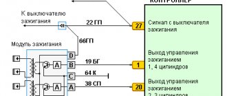
The BSZ diagram for the VAZ 2107 is shown in the photo below.
Ignition circuit for VAZ 2107
Based on this diagram, let's consider the principle of its operation:
- When you turn the ignition key, current is supplied to the primary winding of the coil, thereby creating a magnetic field.
- When the engine starts, power is supplied to the starter coil and the rotor begins to turn the crankshaft.
- In this case, the crankshaft rotates the distributor shaft, which is connected to the runner.
- As soon as the shaft with the slider rotates, this phenomenon is detected by the Hall sensor (along the protrusion on the shaft) and transmits the corresponding signal to the switch.
- When a signal arrives at the switch, the primary winding of the coil is de-energized (on the low-voltage side).
- A powerful discharge of about 25-30 kV is induced in the secondary (high-voltage) winding, transmitted to a moving contact located at the end of the distributor shaft.
- When the slider moves in a circle, it practically touches the contacts in the cover, a spark occurs between them, and a high voltage discharge is transmitted to each of the contacts in turn.
- This discharge flows through armored cables to the spark plug electrodes.
Pros and cons of the system
If you decide to install a carburetor-type BSZ on a VAZ 2107, then it is recommended that you first understand all the advantages and disadvantages of the device. The advantages of the mechanism under consideration include:
- The absence of contacts automatically eliminates the need for their maintenance. As a result, we have a more reliable system that does not require frequent maintenance.
- Stability of spark propagation through the cylinders, which is due to the absence of the breaking effect of the contacts using the cam method.
- A large discharge in the spark plug, the value of which reaches 25-30 kV, while in contact modules it does not exceed 12 kV. High voltage promotes a stronger spark and improved ignition of the fuel assembly, as well as its complete combustion.
- Simplified engine starting at low temperatures.
Ignition adjustment of VAZ-2107
Correct ignition adjustment is one of the most important procedures required for all cars. The exception is modern expensive models. This procedure can significantly reduce consumption, improve dynamic characteristics and increase the efficiency of the power unit as a whole. Neglecting the ignition settings can lead to complete failure of the power unit. As a result, the owner will be forced to pay for expensive repairs.
Remember that before adjusting the ignition of the VAZ 2107, the carburetor must already be pre-configured. Following this recommendation will save time during the work process. Next, we will take a closer look at the ignition adjustment procedure.
Ignition installation for VAZ 2107
To quickly set up the ignition on a VAZ-2107 with your own hands, you need to prepare a special 38 mm key and a multimeter. A strobe light is considered the best device for making adjustments, and an ohmmeter is recommended for models with a contact ignition system. The instructions below are universal for all basic modifications of 2107, since minor design differences do not affect the location and method of disassembling, repairing or adjusting segments and main components.
- Preparation. Preparatory operations are an important part of any repair work. The safety, time costs and effectiveness of manipulations depend on their implementation. Shift into neutral, then disconnect the negative terminal from the battery. This will prevent a short circuit during the setup process, which can lead to failure of expensive electronic components, damage to the wiring and injury to the technician.
- Disassembling the distributor cover. To do this, press the spring clips with a screwdriver to remove the protective cover.
- Installing the crankshaft in the desired position. At this stage, in order to correctly set the ignition of the VAZ-2107, you will need a 38 mm key. With its help, you need to turn the crankshaft clockwise. Change the position of the mechanism until the upper end of the side contact of the distributor slider is aligned with the first contact of the distributor cap. For the next step we will need a measuring device.
- Ignition control. Slowly wind the crankshaft until the mark aligns with one of the lines located on the distributor cap. The long strip on the distributor corresponds to 0° when setting the advance angle, the mark in the center is 5°, and the short notch is 10°. If you are using 92 or 95 octane gasoline, it is recommended to select the middle value. It should be understood that these parameters are used in relation to VAZ-2107 models. If the setting is done correctly, at the moment the marks are connected into one line, the resistance indicated on the device will increase to infinity, which will indicate the correct ignition setting. Otherwise, the system must be calibrated.
- Resistance measurement. This procedure will be described using an ohmmeter as an example. Connect one probe of the device to ground, and the second to the contact bolt of the distributor. The counter scale should show zero value; do not disconnect it from the parts.
- Adjusting the angle of attack. Using a wrench, loosen the lock nut that secures the distributor to the cylinder block. Next, you need to remake the distributor body. Turn the part clockwise until the resistance is zero. When you reach the required value, stop. From the “zero” position, begin to slowly rotate the distributor in the opposite direction until the resistance begins to increase. To eliminate play in the roller drive, carefully move the slider in the opposite direction clockwise. Having obtained the desired result, tighten the distributor fastening nut and install the cover. To perform this procedure, you can use a 12 V test lamp. This method is very dangerous, since the procedure is carried out with the ignition on. Failure to take precautions may result in electric shock or damage to vehicle wiring. When the contacts are opened by a switch, a pulse with a force of up to 300 V is generated in the circuit.
Diagnostics of ignition timing without special equipment or intervention in the design
To check, you need to select a section of the road without road users. Warm up the engine, go out onto a flat area, accelerate to 50 km/h. Then engage fourth gear and press the gas quite hard. If at this time a knock in the engine cylinders appears for no more than 3 seconds, it means that the ignition is set correctly, which is determined by the effect of an unusual ringing sound. The duration of detonation at the specified time indicates that it is necessary to slightly reduce the advance angle value. However, if there is no anomaly, the angle must be increased. This procedure allows the transmission to be perfectly matched to the quality of the fuel used to ensure maximum engine efficiency.
As you can see, adjusting the ignition of a VAZ 2107 in practice turns out to be a fairly simple task. Above, we examined the main aspects and main nuances that arise in the process of carrying out this operation. Our tips can help almost any novice driver complete the installation themselves, saving a lot of money. If you are not very familiar with the design of your vehicle, we recommend that you carry out the adjustment using technical documentation or under the supervision of an experienced technician. Strict adherence to safety rules and preparatory procedures will minimize the likelihood of various undesirable situations occurring.