Itelma m74 can typical parameters
one-time blocking (for one trip). - turn on the ignition - fasten and unfasten the driver's seat twice within no more than 10 seconds; a single lock will be canceled if the ignition is subsequently turned off for more than 60 seconds.
long-term blocking - turn on the ignition - press the button on the front panel of the instrument cluster - while holding the button pressed, fasten and unfasten the driver's seat belt twice within no more than 10 seconds; long-term blocking will be canceled if, with the ignition on and the button pressed, the driver is fastened three times within no more than 15 seconds and unfasten the driver's RB.
any blocking will be canceled when the power is turned off according to class 30
This topic has no curator. For questions about filling out the header, please contact the section moderators via the “Complaint” button under the messages to which you need to add links.
Please move the information here to the header:
Example of installing a rear view camera on Kalina II Forced activation of the rear view camera from the button Additional information on the car AT commands for 3G HUAWEI modems Connecting DVB-T2 to MMC
You can also rummage around on the previous topic. It would be right.
Write with links, we’ll save up a little and write to the moderator so that he can transfer them en masse.
Added 06/23/2014, 11:53:
It is more convenient (for me personally) to have errors and additional vehicle parameters on an additional device. I use Multitronics VC731. Installed it like this:
Source
Typical diagnostic parameters for Lada Kalina with Bosch МE17.9.7 and M74 controllers
ECU M73 and everything connected with it (Firmware, standard parameters, immo, training)
appeared on the VAZ
in 2008 in connection with the transition to
Euro-3
.
From a circuit design point of view, this unit is the closest relative of the already familiar Mikas-11 and January-7.2+.
M73
controllers are produced by two factories: NPO ITELMA and AVTEL. The hardware of the controllers is identical, but the software is fundamentally different.
Built on the ST10F processor
The hardware unit is almost identical to January 7.2+
, the only difference is in the resistors responsible for the processor configuration. This allows, with some restrictions, to remake the M7.3 in January 7.2+
Since 2007, the production of control units based on the ST 10- processor (January 7.2+, M73) began. M 73 control unit for cars with Euro-3 toxicity standards - analogue Bosch 7.9.7+ The software of the M73 and January 7.2+ control units is incompatible. Installed on cars: Since the end of 2007 - front-wheel drive, Since 2008 - classic, Since 2009 - Kalina, Priora
Communities › VAZ: Repair and Modification › Blog › Flashing Classics with M74k
Programming M74k (Classic)
Since 2011, all new cars coming off the assembly line, including classic cars, must comply with Euro 4 standards. The M74 and M74K blocks are incompatible and different in circuit design. M74K, in fact, is not M74, it is a “global” modification of the M73 block, that is, the ST10F273 processor is used (the same as in January 7.2+ and M73)
, reading/writing by the Combiloader programmer is possible in M73 mode. The M74 ECU is not wiring/connector compatible with any previously used ECU.
As we see on the classic e-gas, roughly speaking, a modified M73 block, turned it into an M74K on the same ST10F273 processor as the M73. And that means we can flash it using improvised means using the ST10Flasher bootloader, because... it works via BSL mode with this kind of processor.
We will need: 1. K-line adapter Romo cable in my case 2. ST10Flasher (Download for free from the Internet) Only descript understands. 3. Firmware (Buy from the authors, find, etc.) Firmware size 589,824 bytes. Decript. 4. Soldering iron, resistor 5. Hands, that seems to be all
.
When removing the ECU from the car, do not forget to first disconnect the battery terminal.
Connector 1 (Large) B2
- switchable voltage (K15)
J2
- non-switchable voltage (K30)
M3
- 12V after the main relay
L2;L3;H1
- ground
C1
- K-Line
We also need to convert to BSL (BootStrapLoader)
mode, the so-called Buta mode.
Switch the resistor from leg 105 to leg 104, just like in the M73 block, but the tracks are slightly redesigned, and you won’t be able to flip it over without problems
as on the M73 block, it is better to add
4.7 kOhm - 10 kOhm
for the reprog time.
Did you transfer?
Now we connect according to the pinout above, all contacts except
B2 for switchable power. You can put a button on it, or you don’t have to.
You can use an adapter, for example MasterKit, it does not switch 12 volts itself, you will have to take the power from the battery or power supply and connect it in parallel to the computer. That is, take power from the battery to both the adapter and the computer.
Next, connect the online adapter to the laptop, go to ST10Flasher
configure the port, select M73, wait a while, then connect
B2
, and click on the button to establish a connection.
“Connection with the ECU has been established” is displayed at the bottom.
, read
Flash
, then
EEPROM
just in case.
(Although the classic does not have an immobilizer, it would not be superfluous to consider EEPROM). And finally, click Load Flash
- select the firmware and wait for the result to finish.
After reprog, disconnect the adapter from the laptop, and DO NOT forget to return the smd resistor to the stock location.
Next, install the ECU in place, connect the battery terminal, and do not forget to reset the ECU with initialization when you turn on the ignition for the first time.
Short way to reset the ECU with initialization. OpenDiagFree, Connect to diagnostics, go to the “Errors” section and click the “Reset ECU with initialization” button. My blog has more details on how to reset, etc.
ATTENTION!
ATTENTION! ATTENTION! Some photographs and information materials were taken from Drive2 and the World Wide Web! To a greater extent CHIPTUNER.RU
And remember:
Everything you do is done at your own peril and risk PS.
The stingy one pays twice, go to a chiptuner who will upload the firmware for you using official software. Source
ECU M73
Photo of the M73 ECU board
There are 2 types of software for this ECU:
Please note that the ECU can be produced both at the AVTEL plant and at the ITELMA plant, respectively, the firmware identifiers will begin with the letter “A” or “I”:
The ELKAR/ITELMA software can currently only be found on front-wheel drive cars, and the VAZ software can only be found on classics and Kalinas. These types of software have nothing in common with each other, that is, they differ fundamentally in their algorithmic model.
ITELMA projects have software related to Mikas-11. The fundamental difference is only in the algorithm of operation of the detonation channel (in Mikas-11 the ELKAR model is implemented, which we have known in a simplified form since the time of Mikas-7.1, and in the M73 software the VAZ model is implemented, similar to the ECU January-5/7 model). Theoretically, this software can work with DBP, and the MAF/DBP operating mode is switched by the configuration flag).
Calibrations M73 ELKAR/ITELMA in ChipTuningPRO
The VAZ project has its own software, which is a further development of the January-7.2 software. Many calibrations in this software are similar to similar calibrations of the January-7.2 ECU, both in name and in algorithmic purpose.
Calibrations M73 VAZ in ChipTuningPRO
You can work with M73 if you have purchased additional modules for the bootloader and ChipTuningPRO.
Diagnostics of an ECU with VAZ software (21067-1411020-22) is possible using the current version of SMS-Diagnostics, if you select the ECU type Bosch M7.9.7 (diagnostic protocols are identical). The AVTEL software protocol is similar to the Mikas-11 ECU protocol. Diagnostic support for these ECUs is already implemented in SMS-Diagnostics.
The M73 VAZ electronic control units (ECUs) use ST10F273 microcontrollers. But they are not on sale, you can replace them with ST10F276 which costs $4 on aliexpress, but for some reason ST10F273 is much more expensive. ST10F276, unlike ST10F273, has a larger memory i.e. it is no worse than ST10F273 and is an excellent replacement.
To simplify diagnostics, the main elements and diagnostic points have been identified:
The transistor and fan control resistor are shown in green and are used on Kalina and Priora.
Main malfunctions of the M73:
2) If there are problems with the idle speed controller IAC - TLE4729, this microcircuit controls the stepper motor.
3) Power is provided by the TLE4471 +5V microcircuit; control points are indicated on the board. Please note that there are three power supply microcircuits in the diagram; in fact, the M73 has one TLE4471, and the January 7.2+ also has a TDA3664.
4) There is only one varistor on the board and sometimes it short-circuits +/-12V due to overvoltage in the ECU power supply.
6) If the controller does not communicate via the diagnostic line, then the reason may be the L9637 K-line driver or quartz (if the controller shows no signs of life at all).
January 7.2+ differs from M73 in the configuration of resistors around the controller, the presence of a TDA3664 voltage regulator, and M95080 memory.
Description of ECU contacts:
Green color indicates contacts used in systems with 2 DCs (Euro III) Red color indicates contacts used in 16 cell systems 21124 No.
| Compound | |
| 1 | 21114 - Not used / 21124 - Ignition coil 2 cylinders. |
| 2 | 21114 - Ignition 2-3. Control of the primary winding of the ignition coil, act. level is low. /21124 — Ignition coil 3 cylinders. |
| 3 | Ignition circuit weight |
| 4 | 21114 - Not used / 21124 - Ignition coil 4 cylinders. |
| 5 | 21114 - Ignition 1-4. Control of the primary winding of the ignition coil, act. level is low. /21124 - Ignition coil of cylinder 1. |
| 6 | Injector 2. Active level low |
| 7 | Injector 3. Active level low |
| 8 | Output to tachometer. |
| 9 | Not used |
| 10 | Fuel consumption signal |
| 11 | Not used |
| 12 | Battery, terminal 30 of the ignition switch. |
| 13 | Nutrition. Ignition switch terminal 15 |
| 14 | Main relay |
| 15 | Contact "A" DPKV |
| 16 | TPDZ |
| 17 | Weight of TPS/Weight of TPS, DND |
| 18 | Input - oxygen sensor |
| 19 | Input - knock sensor |
| 20 | Knock sensor weight |
| 21 | Not used |
| 22 | Not used |
| 23 | Not used |
| 24 | Not used |
| 25 | Bosch Only - High Current Output, Reserved |
| 26 | Bosch Only - High Current Output, Reserved |
| 27 | Injector 1. Active level low |
| 28 | Not used /DK2 heater control output |
| 29 | Not used / Engine cooling fan control output 2 |
| 30 | Not used |
| 31 | CE lamp, act. level low |
| 32 | Power supply TPDZ / Power supply TPDZ, DND |
| 33 | Power supply for mass air flow sensor |
| 34 | DPKV input, contact “B” |
| 35 | Weight of DTOZH /Weight of DTOZH, mass air flow sensor, 1 DC (UDK), 2 DC (DDK) |
| 36 | Mass of the mass air flow sensor |
| 37 | Signal input from mass air flow sensor |
| 38 | Not used |
| 39 | Signal input from DTOZH |
| 40 | Signal input from intake air temperature sensor |
| 41 | Not used |
| 42 | Not used / DND signal input |
| 43 | Not used |
| 44 | On-board voltage input at the main relay output |
| 45 | Phase sensor power output |
| 46 | Canister purge valve control output |
| 47 | Injector 4. Active level low |
| 48 | Oxygen sensor heater control output |
| 49 | Not used |
| 50 | Additional starter relay control output |
| 51 | Controller weight |
| 52 | Not used |
| 53 | Controller weight |
| 54 | Not used |
| 55 | Not used / Signal input DK2 (DDK) |
| 56 | Not used |
| 57 | Input for encoding calibration data options. The controller memory can contain 2 sets of calibration data; switching is performed by shorting to ground. |
| 58 | Not used |
| 59 | Speed sensor |
| 60 | Not used |
| 61 | Weight of output stages |
| 62 | Not used |
| 63 | On-board voltage input at the main relay output |
| 64 | Output “D” IAC |
| 65 | Output “C” IAC |
| 66 | Output “B” IAC |
| 67 | Output “A” IAC |
| 68 | Engine cooling fan relay control output, act. level - low |
| 69 | Air conditioner relay control output, act. level - low |
| 70 | Fuel pump relay control output, act. level - low |
| 71 | K-Line |
| 72 | Not used |
| 73 | Not used |
| 74 | Not used |
| 75 | Input request to turn on the air conditioner, act. level - high |
| 76 | Power steering request input, act. level - high |
| 77 | Not used |
| 78 | Not used |
| 79 | Phase sensor signal input |
| 80 | Weight of output stages |
| 81 | Not used |
In addition, it can be noted that the ST10F273 is a microcontroller, not a processor. The fact that it is more complex than the PIC12F675 microcontroller does not make it a processor. You can make sure at the off. website or on Wikipedia where there are even examples of microcontroller manufacturing companies where STM is included, and you can also see what the STM company produces and there are no processors there. For example, Intell (off site) (Wikipedia) produces processors, it clearly states that they have processors, not microcontrollers. Why in everyday life does everyone talk about a microcontroller processor - it seems easier for everyone.
If you have January 7.2+, then it can be converted to M73 (resoldering the configuration resistors).
Attention, beware of fakes:
3 pieces of 276 controllers were ordered and all three had the same defect: there was a short circuit when power was applied
[66.64 Kb] (downloads: 65) datasheet for ST10F273 and ST10F276
[77.93 Kb] (downloads: 101) diagram in P-CAD of ECU M73
Lada Granta Belka in the clouds › Logbook › The story of how I repaired and flashed the M74CAN ECU
Hello everyone! I warn you, there are a lot of pictures and text. ) And my resulting skills in flashing and repairing ECUs. I have a non-working ECU, the control circuits for the devices did not work: fuel pump, Carlson, starter. Plus, the EEPROM in which the adaptation parameters are stored was covered. There were impulses to the injectors and a spark to the candles. It was not possible to start the car on the spot for the reason that I, not having a diagram at hand, tried to control the relays with a plus, but they, as it turned out, were waiting for a minus from the brain. Now I understand that I could not have bothered with turning it on through the relays at all, but simply closed the necessary outputs, but at that moment the Great Stupid visited me.
So they dragged me home on a cable, the battery was completely dead, not even enough for the emergency lights. At home, I rummaged through the Internet, studied the circuit and powered everything I needed by forcibly planting the inputs of the relays to the ground through toggle switches. Starting a car began to resemble starting an airplane or infantry fighting vehicle: “Fuel pump, ignition, starter fuse, start!” Plus Carlson is turned on in manual mode.
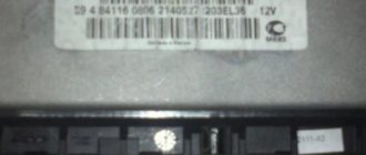
After searching on the Internet, I found an ECU in Kazan. A friend helped me buy and deliver. The ECU number is identical, the printed circuit board is identical, the only difference is in the firmware. ECU number: 11186-1411020-22 Signet version: M74_v6.36 Both were released in 2012 Firmware versions: I484GG03 (native), I484GI06 (purchased)
After installing the ECU, the engine started, but the speedometer did not work. It works on a burnt block, which means the problem is not with the speed sensor (DS). Accordingly, the dragator does not behave correctly when moving and generates error P0500. I rummaged for a long time and came to the conclusion that the block was installed on a car with ABS, where the speed is not taken from the DS on the box, but comes, as I understand it, via the CAN bus directly from the ABS mathematics.
Long research began on the topic of ECU programming and reset with initialization. I tried to do a reset with initialization according to this guide, the program was unable to communicate with the ECU through the existing adapter. I tried the “Forsage” function in BC STATE, but it didn’t help. I decided that only firmware would help the father of Russian democracy. But the price tag for firmware in Omsk is not reasonable, although I found a person willing to re-upload the stock firmware for 1500. Also, in a telephone consultation with one of the technicians, I said that my ECU (old) throws an EEPROM error during operation, to which I heard “that means there’s nothing that can be done to help it.” Strange words for a person positioning himself as an ECU repair specialist. After all, digging through the Internet, I found out that the latest firmware does not use external EEPROM at all; instead, adaptive data is written to FLASH inside the processor, following the firmware. Thus, by flashing to another firmware that uses flash, you can bypass this problem. In short, once again I was convinced that not all masters are such and once again I decided to rely on myself.
After reading the blog post by the same author and learning on the Internet about the insignificant difference between the M74 and M74CAN blocks, I decided to modify the latter. I soldered the missing K-line chip L9637D and the harness into it, as it turned out, only a pull-up resistor is needed, everything is marked in the picture.
I assembled the wiring to connect the bm9213 masterkit adapter to the block.
IMPORTANT! The K-line contact will be on port G3 in a large connector!
Source
Closed ECU versions
Since the end of 2009, all new versions of the M73 and Mikas-11 ECUs are “closed”, that is, protected from reading and writing the firmware in the usual ways. When you try to read such an ECU through the BootLoader of the processor, the read dump will contain “garbage” in the form of a byte sequence: 9B 00 9B 00 9B 00. When you try to read it using the diagnostic method (without opening the ECU), the bootloader will display the message “Error starting the bootloader.” Please note that in this case you cannot attempt to write firmware to the unit using the usual methods; this may lead to complete inoperability of the ECU! To work with “closed” ECUs, we have developed a special module for the bootloader.
