02 September 2020 Lada.Online 7 801 0
When connected to the diagnostic block, we receive data from sensors that enter the engine control unit. Knowing the typical values of the main parameters, you can analyze the operation of the engine and its systems, find the cause of the malfunction or determine the direction in which to look for the cause of problems in the operation of the car. The following are typical diagnostic parameters for Bosch ME17.9.7 (article 11194–1411020-20) and M74 (11183–1411020-51/52 and 11183–1411020-01/02) for the Lada Kalina.
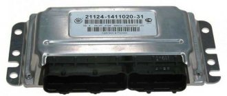
Bosch ME17.9.7 controller
| Parameter | Decoding | units change | Idling | 3000 rpm |
| TANS | Air temperature | °C | 15° – 45° | 15° – 45° |
| TMOT | Cooling temperature liquids | °C | 82° – 104° | 82° – 104° |
| UBSQ | Onboard voltage | IN | 13.0 – 14.5 | 13.0 – 14.5 |
| WPED | Pedal position | % | 0 | 8 – 15 |
| WDKBA | Throttle position | % | 1 – 4 | 6 – 10 |
| NSOL | Desired speed | RPM | 840 | — |
| NMOT | Engine speed | RPM | 840±40 | 3000±100 |
| MI | Air flow | Kg/h | 7.0 – 12 | < 40 |
| ZWOUT | UOZ | Grd. P.K.V | 9±5 | 30 – 40 |
| WKRV | Detonation angle rejection | hail | 0 | ‑2.5 – 5 |
| RI_W | Load | % | 17 – 26 | 17 – 26 |
| FHO | Barocorrection factor | 0.89 – 1.02 | 0.89 – 1.02 | |
| TIEFF | Injection time | msec | 2.7 – 3.9 | 2.1 – 5.3 |
| DMVAD | Adaptation of XX adjustment | % | ±5 | ±5 |
| USVKL | Signal from DC1 | IN | 0.01 – 0.89 | 0.01 – 0.89 |
| USVKL | Signal from DC2 | IN | 0.01 – 0.89 | 0.01 – 0.89 |
| FR_W | Lambda correction factor | 1.0±0.15 | 1.0±0.15 | |
| FRA_W | Lambda adaptation factor | 1.0±0.15 | 1.0±0.15 | |
| TATEOUT | Purge the adsorber | % | 0 – 12 | Not really |
| FUCOTE | Loading the adsorber | % | 0 – 2 | 0 – 2 |
| MSLEAK | Coeff. adaptation of fuel at XX | kg | ±2.5 | ±2.5 |
| MSNDKO | Leaks at XX | kg/h | 1 – 10 | 1 – 10 |
| DTPPSVKMF | Period of the 1st DC | sec | < 1.9 | < 1.9 |
| FZABGZYL_1‑4 | Misfires | 0 | 0 | |
| FZKATS | Misfire influencing workers neutralizer | 0 | 0 | |
| DMLLRI | Tech. correction XX | % | ±8 | 0 |
| DMLLR | Tech. correction XX | % | ±8 | 0 |
| AHKAT | Neutralizer aging factor | < 0.45 | < 0.45 | |
| UDKP1 | Eg. damper sensor 1 | B | 0.56 – 0.66 | — |
| UDKP2 | Eg. damper sensor 2 | B | 4.30 – 4.50 | — |
| UPWG1ROH | Eg. accelerator sensor 1 | B | 0.43 – 0.50 | — |
| UPWG2ROH | Eg. accelerator sensor 2 | B | 0.21 – 0.26 | — |
| RINV | DC Resistance 1 | Ohm | 60 – 140 | — |
| RINH | DC Resistance 2 | Ohm | 60 – 140 | — |
| B_LL | Bit XX | Yes | No | |
| B_LR | Closed Loop Adjustment Bit | Yes | Yes | |
| B_LRA | Resolution bit fuel adaptation | Not really | Not really | |
| B_SBBVK | DK ready bit 1 | Yes | Yes | |
| B_SBBHK | DK 2 ready bit | Not really | Not really | |
| B_SZCAT | Neutralizer Test Complete Bit | No Yes | No Yes | |
| B_NOLSV | DK test completion bit 1 | No Yes | No Yes | |
| B_NOLSH | DK 2 test completion bit | No Yes | No Yes | |
| B_FOFR1 | Pulley learning bit | No Yes | No Yes | |
| B_TE | Canister purge bit | No Yes | No Yes | |
| DFC_TEV | SUBS test completion bit | No Yes | No Yes | |
| B_KUPPL | Clutch pedal sensor bit | No Yes | No Yes | |
| B_BREMS | Brake Pedal Sensor Bit | No Yes | No Yes | |
| DFES | Fault codes | |||
| Rail fuel pressure | kPa | 380±20 | 380±20 |
Typical parameters of the Itelma M74 computer
one-time blocking (for one trip). - turn on the ignition - fasten and unfasten the driver's seat twice within no more than 10 seconds; a single lock will be canceled if the ignition is subsequently turned off for more than 60 seconds.
long-term blocking - turn on the ignition - press the button on the front panel of the instrument cluster - while holding the button pressed, fasten and unfasten the driver's seat belt twice within no more than 10 seconds; long-term blocking will be canceled if, with the ignition on and the button pressed, the driver is fastened three times within no more than 15 seconds and unfasten the driver's RB.
any blocking will be canceled when the power is turned off according to class 30
This topic has no curator. For questions about filling out the header, please contact the section moderators via the “Complaint” button under the messages to which you need to add links.
Please move the information here to the header:
Example of installing a rear view camera on Kalina II Forced activation of the rear view camera from the button Additional information on the car AT commands for 3G HUAWEI modems Connecting DVB-T2 to MMC
You can also rummage around on the previous topic. It would be right.
Write with links, we’ll save up a little and write to the moderator so that he can transfer them en masse.
Added 06/23/2014, 11:53:
It is more convenient (for me personally) to have errors and additional vehicle parameters on an additional device. I use Multitronics VC731. Installed it like this:
M74 controller
| Parameter | Decoding | units change | Idling | 3000 rpm |
| TANS | Air temperature | °C | 15° – 45° | 15° – 45° |
| TMOT | Cooling temperature liquids | °C | 90° – 101° | 90° – 101° |
| UBSQ | Onboard voltage | IN | 13.0 – 14.5 | 13.0 – 14.5 |
| WPED | Pedal position | % | 0 | 11 – 15 |
| WDKBA | Throttle position | % | 2 – 5 | 7 – 11 |
| NSOL | Desired speed | RPM | 840 | 3000 |
| NMOT | Engine speed | RPM | 840 ±40 | 3000 ±100 |
| MI | Air flow | Kg/h | 7 – 12 | 27 – 35 |
| ZWOUT | UOZ | Grd. P.K.V | 9 ±5 | 32 – 35 |
| RL_W | Load | % | 16 – 26 | 12 – 17 |
| FHO | Barocorrection factor | 0.8 – 1.02 | 0.8 – 1.02 | |
| TIEFF | Injection time | msec | 3.0 – 5.0 | 2.8 – 3.5 |
| DMVAD | Adaptation of XX adjustment | % | ±5 | — |
| USVKL | Signal from DC1 | IN | 0.01 – 0.89 | 0.01 – 0.89 |
| USHKL | Signal from DC2 | IN | 0.01 – 0.89 | 0.01 – 0.89 |
| FR_W | Lambda correction factor | 1.00 ±0.02 | 1.00 ±0.02 | |
| FRA_W | Lambda adaptation factor | 1.00 ±0.15 | 1.00 ±0.15 | |
| TATEOUT | Purge the adsorber | % | 0 – 8.2 | 0 – 18 |
| MSLEAK | Coeff. adaptation of fuel at XX | kg | ±2.5 | — |
| MSNDKO | Leaks at XX | kg/h | 2 – 8 | — |
| DTPPSVKMF | Period of the 1st DC | sec | < 1.8 | < 1.8 |
| FZABGZYL 1–4 | Misfires | 0 | 0 | |
| FZKATS | Misfire influencing workers neutralizer | 0 | 0 | |
| DMLLRI | Tech. correction XX | % | ±8 | |
| DMLLR | Tech. correction XX | % | ±8 | |
| AHKAT | Neutralizer aging factor | < 0.45 | < 0.45 | |
| B_LL | Bit XX | Yes | No | |
| B_LR | Closed Loop Adjustment Bit | Yes | Yes | |
| B_LRA | Resolution bit fuel adaptation | Not really | Not really | |
| B_SBBVK | DK ready bit 1 | Yes | Yes | |
| B_SBBHK | DK 2 ready bit | Not really | Not really | |
| B_TE | Canister purge bit | No Yes | No Yes | |
| B_KUPPL | Clutch pedal sensor bit | No Yes | No Yes | |
| B_BREMS | Brake Pedal Sensor Bit | No Yes | No Yes | |
| DFES | Fault codes | |||
| Rail fuel pressure | kPa | 380 ±20 | 380 ±20 |
Note: * All parameters are given for positive ambient temperature. Parameter values are advisory in nature. Source chiptuner.ru
Computer diagnostics of a car engine
Comprehensive diagnostics of a car engine are carried out exclusively in car services equipped with special computers with LCD screens and devices connected to them.
The set of necessary equipment for diagnosing a car should include:
- personal computer;
- fast-response digital six-channel monotester;
- universal system scanner;
- four-component gas analyzer;
- mobile lockable stand with a large number of functions for diagnostics.
All of the above devices must have insulated wires and be located in one place.
Experts recommend carrying out comprehensive diagnostics of the car if incorrect operation of sensors and units , as well as if uncharacteristic sounds appear during engine operation. Then such a technical inspection will help to avoid unexpected breakdowns and prevent unnecessary financial costs.
Replacing the air flow sensor
To replace the sensor with your own hands, you need to prepare a shaped screwdriver and a “10” key.
The replacement procedure consists of the following steps:
Disconnecting the sensor connector
Thus, if the car stalls and has all the signs of a breakdown of the mass air flow sensor, then before you start repairing it, you should check the level of its signal, it should not be low, perform a full diagnosis of the car and repair all faulty components and parts.
It is important to undergo regular vehicle inspections and perform timely maintenance, then the parts and components will last longer.
Term: ADC
Analog-to-digital converter (ADC) is a device that converts an input analog signal into a digital signal (digital binary code). For tasks of measuring the value of a signal at an arbitrary point in time, an asynchronous mode of operation with an ADC with single analog-to-digital conversions that are not strictly time-bound is used. For tasks of measuring the functional dependence of changes in an analog signal, the synchronous operating mode of the ADC is used. The synchronous mode of operation of the ADC without missing data over an arbitrarily large time interval is also called streaming mode. Synchronous ADCs, as a rule, support the frame-by-frame principle of data acquisition, when digitized measurement reports form conditional frames with a specified number of samples corresponding to specified measurement channels.
The ADC is an integral part of the data acquisition system.
Main parameters of the ADC:
How to reset error codes
After automatic diagnostics, errors must be reset. This is done so that they do not interfere or confuse the user during subsequent diagnostics. You can find out how to reset everything from the manufacturer's recommendations. But in practice, for example, an ECU error is reset by running a new check on the dashboard. In the service station, the controllers are reset in a slightly different order. There are other options:
Specialists will help you sort out the problems if you yourself don’t know how to get rid of them.
How to deceive the mass air flow sensor using ECU firmware
The good thing about the previous method is that its implementation does not require complex equipment or painstaking work. If you were able to check the voltage at the output of the flow meter with a multimeter (which means you at least have one), and know how to hold a soldering iron in your hands, installing a resistor in the wire gap will not be difficult. However, the dependence of voltage on air flow mass is nonlinear. And when the throttle valve opens, the error of the signal corrected by the resistor at rest will increase. Accordingly, the fuel-air mixture will not be ideal.
Decoding error codes Kalina 1.6 8 and 16 valves
Many owners of this model will be interested in knowing how error codes for Kalina 1.6 8 and 16 valves are deciphered. The on-board computer installed in the car not only controls the operation of the car's systems, but can perform self-diagnosis and inform the driver about any malfunctions in the car. This significantly increases safety and increases the service life of machine components and assemblies. Every driver of this model must be able to deal with emerging alarms in a timely manner.
Decoding error codes for Kalina 1.6 8 and 16 valves will be shown in this article.
You can make a printout and take it with you. If suddenly an alarm signal appears during a trip, it will be much easier for the driver to make the right decision about what to do in the situation that has arisen, continue the trip or wait for help from specialists. The system works in such a way that errors from problems that arise are stored by the on-board computer. They can be read later using special diagnostic equipment.
How to perform diagnostics yourself?
Sometimes even the most reliable and smart cars malfunction during operation. This can fully be attributed to Kalina. The on-board computer of this model is capable of analyzing the current situation and telling the driver about problems. You can test the car in specialized centers or yourself. There is a possibility of errors during self-diagnosis, but it is advisable to carry it out.
Self-check procedure:
DIY diagnostics of Lada Kalina 1, 2
Diagnostics by car models April 2, 2022 Rating:
Reading time
Difficulty of the material:
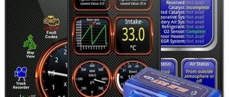
To independently carry out computer diagnostics of the Lada Kalina via a laptop or smartphone, just connect to the OBD2 connector with a diagnostic adapter and a car scanner. In 90% of cases, comp. Auto diagnostics boils down to reading data from the ECU, but not every driver knows how to do this correctly.
This manual describes in detail the process of connecting to the “brains” of the car, including which auto scanner and program to choose. In the article you will find many useful links to more detailed instructions and site materials.
Author of the site elm327-obd2.ru
Features, diagnostics and replacement of elements of injection systems on VAZ cars
Below we will look at the main controllers!
Hall
There are several options for how you can check the Hall sensor of a VAZ:
The replacement procedure is performed as follows (the process is described using the example of model 2107):
Speeds
The following symptoms may indicate a failure of this regulator:
Fuel level
The VAZ or FLS fuel level sensor is used to indicate the remaining volume of gasoline in the fuel tank. Moreover, the fuel level sensor itself is installed in the same housing with the fuel pump. If it malfunctions, the readings on the dashboard may be inaccurate.
The replacement is done like this (using the example of model 2110):
Photo gallery “Changing the FLS with your own hands”
Idle move
If the idle speed sensor on a VAZ fails, this is fraught with the following problems:
To solve the problem of device inoperability, the VAZ idle speed sensor can either be cleaned or replaced. The device itself is located opposite the cable that goes to the gas pedal, in particular, on the throttle valve.
The VAZ idle speed sensor is fixed using several bolts:
Crankshaft
The VAZ crankshaft sensor is used to synchronize the operation of the fuel supply and ignition systems. Diagnosis of DPKV can be made in several ways.
To replace the DPKV, do the following:
Lambda probe
The VAZ lambda probe is a device whose purpose is to determine the volume of oxygen present in the exhaust gases. This data allows the control unit to correctly create the proportions of air and fuel to form a combustible mixture. The device itself is located on the exhaust pipe of the muffler, at the bottom.
The regulator is replaced as follows:
Let's compare architectures
At the moment, there are many different ADC architectures in the world. Each of them has its own advantages and disadvantages. There is no architecture that would achieve the maximum values of all the parameters described above. Let's analyze what maximum speed and resolution parameters the companies producing ADCs were able to achieve. We will also evaluate the advantages and disadvantages of each architecture (you can read more about the various architectures in the article on Habr). Architecture comparison table
| Architecture type | Advantages | Flaws | Maximum resolution | Maximum sampling rate |
| flash | Fast converter. The conversion is carried out in one clock cycle. | High power consumption. Limited resolution. Requires a large crystal area (comparators). It is difficult to coordinate a large number of elements (as a result, low yield). | 14 bit 128 kSa/s AD679 | 3 bit 26 GS/s HMCAD5831 |
| folding-interpolated | Fast converter. The conversion is carried out in one clock cycle. Requires fewer comparators due to preliminary “convolution” of the entire processing range into a narrower range. Occupies less space. | Errors associated with the nonlinearity of the convolution block. Delay for establishing levels in the convolution block, which reduces the maximum fs. Medium resolution. | 12 bit 6.4 GS/s ADC12DL3200 | 12 bit 6.4 GS/s ADC12DL3200 |
| SAR | High accuracy. Low power consumption. Easy to use. | Limited speed. | 32 bit 1 MSa/s LTC2500 | 10 bit 40 MSa/s XRD64L43 |
| pipeline | Fast converter. Highest accuracy among fast ADCs. Doesn't take up a large area. Has lower consumption among similar fast converters. | Pipeline delay. | 24 bit 192 kSa/s AK5386 | 12 bit 10.25 GS/s AD9213 |
| dual-slope | Average conversion accuracy. Simplicity of design. Low consumption. Resistance to changes in environmental factors. | Processes low frequency Signals (low fs). Mediocre resolution. | 12+sign bit 10 S/s TC7109 | 5+sign bits 200 kSa/s HI3-7159 |
| ∑-Δ | The highest conversion accuracy thanks to the “Noise shaping” effect (specific filtering of quantization noise) and oversampling. | Cannot work with wideband signal. | 32 bits 769 kSa/s AK5554 | 12 bit 200MS/s ADRV9009 |

