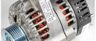
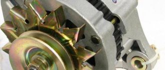
Cars of the VAZ “8, 9, 99” family equipped with a carburetor, fuel injection system (injector) are equipped with generators of type 37.3701, 94.3701.
Both power supplies are AC, three-phase, with pre-installed rectifier and voltage regulator. The rotation side is right.
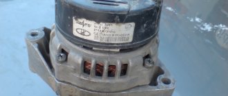
The first type of power source (hereinafter - IP) is driven by a V-belt, and the second - by a poly V-belt from the crankshaft pulley. Some production models of the “eight” and “nine” are equipped with IP made in Slovenia, marked AAK-5102.
If AAK-5102 fails, it can be completely or partially replaced by 94.3701. The process of self-prevention is not at all complicated, but it requires knowledge and initial experience in vehicle maintenance. Carrying out diagnostics in a non-professional manner does not guarantee the functionality of the equipment.
Generator VAZ 21099, VAZ 2109, VAZ 2108
Cars of the VAZ “8, 9, 99” family equipped with a carburetor, fuel injection system (injector) are equipped with generators of type 37.3701, 94.3701.
Both power supplies are AC, three-phase, with pre-installed rectifier and voltage regulator. The rotation side is right.
The first type of power source (hereinafter - IP) is driven by a V-belt, and the second - by a poly V-belt from the crankshaft pulley. Some production models of the “eight” and “nine” are equipped with IP made in Slovenia, marked AAK-5102.
If AAK-5102 fails, it can be completely or partially replaced by 94.3701. The process of self-prevention is not at all complicated, but it requires knowledge and initial experience in vehicle maintenance. Carrying out diagnostics in a non-professional manner does not guarantee the functionality of the equipment.
Types of generators
There are different types of generators for VAZ cars depending on their design. The most common generators are compact in size - 94.3701 and others.
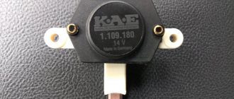
Owners of Russian-made cars install brushless inductor-type generators. For example, devices modification 955.3701. Such generators differ from traditional equipment by the presence of permanent magnets on the rotor and field windings on the stator. Thanks to this, the design of the generator set does not contain slip rings and an alkaline unit, which is one of the most vulnerable and poorly protected.
Generators of type 955.3701 have not previously been used in passenger cars. Now they are manufactured by various Russian enterprises, including the Altai Tractor Equipment Plant. Among the main disadvantages of these electric generators are the high noise level during operation and heavy weight. This must be remembered before choosing a VAZ generator with a brushless design.
What generator is installed on the VAZ 21099, VAZ 2109, VAZ 2108
| Specifications | 37.3701 | 94.3701 |
| Limit current strength at a voltage of 13.5 V and speeds above 5500 rpm | 56 | 81 |
| Adjustable voltage range | 13,5-14,4 | 13,3-14,6 |
| Gear ratio | 01.01.1970 | 01.01.1970 |
| Capacitor capacity | 2,3±15% | 2,1±15% |
Note to the driver!!! If the IP drive belt breaks along the way, and you don’t have a spare one at hand, cut a 25 mm wide ring from the car inner tube.
To significantly reduce current consumption when the power unit is running, it is necessary to turn off the maximum number of current consumers: radio, radio, lighting, cooler, stove heater.
Video “How to properly disassemble and reassemble a unit with your own hands”
Instructions for disassembling and reassembling the generator unit for a VAZ are presented in the video below (the author of the video is Denis Legostaev).
AutoNews / Reviews / Tests
Replacing the VAZ 2109 Generator with a More Powerful One
Replacing the VAZ 2109 generator with a more powerful one
Is a regular generator not enough for you? You often drive at night with your headlights on, lots of fog lights, you like to listen to music differently just for the sake of conviction (winter, heater, heated glass). You can change your own generator to a decimal one. Let's compare the properties of generators:
Standard (37.3701) - current up to 55A at 5000 rpm, gear ratio 1:3.5.04 From 2110 (94.3701) - current up to 80 A at 6000 rpm, gear ratio 1:3.5.4
The naked eye can see that the decimal generator is almost one and a half times stronger. It is natural to assume that with a similar load current, its reliability should become higher. Additionally, during operation at XX, the output power is also more than simple.
First, we evaluate the possibility of alteration. The upper bracket of the tenth generator 94.3701 is fastened with 2.4 bolts, and the lower one with 3, in contrast to the standard 37.3701, where 1 and 4.5 bolts are used, respectively. As follows, there will be two additional holes on the cylinder block, one near the upper generator mounting bracket, the other near the lower one. If you're lucky. they are already natural and on the block.
The next step is to buy what remains to be done for our client:
Generator set price for VAZ 21099, VAZ 2109, VAZ 2108
| Catalog item | Serial number | Price | |
| A2110-80A (original) | BOSCH (9501.3801) (original) | From 3000 – 3200 | |
| 9501.3801 | FINWHALE 687-04 | 62022 / 180545 | From 3000 – 3200 |
| 9568.3749 | 922.3801 | SKL622RS | From 3000 – 3200 |
| 3701010 (HORT) | 3701024 | Contitech | From 3000 – 3200 |
| 3701971 | 3701953 | Electro 3701747 | From 3000 – 3200 |
| *prices are as of August 2022 |
The principle of operation of the power supply VAZ 21099, VAZ 2109, VAZ 2108
There are 6 coils mounted inside the generator set, the material is copper, the connection is star-shaped. The stator is a stationary structure, and the rotor rotates inside the stator. Magnetic brushes are pressed into the back of the rotor axis, and the excitation winding is wound and sealed.
After the key is turned in the ignition switch, the current from the battery creates a magnetic field, passing through the graphite brushes and copper winding. Alternating current is converted to direct current.
On the front side of the IP there are two power outputs with polarity “+” and “-”. Terminals with the appropriate polarity are connected to the battery.
To turn the generator set you will need a battery. After the battery has accumulated the spent amount of energy, the generator distributes the excess to other power sources. Thus, the size of the on-board network is maintained within an acceptable range.
Car generator operation
But there is no magnet in the generator; its functions are performed by the excitation winding. The states can be briefly described as follows:
- When the engine is stopped and the ignition is turned off, all vehicle systems are de-energized and no voltage is supplied to the excitation winding.
- When you turn on the ignition, constant voltage is supplied to the regulator.
- The voltage regulator allows you to stabilize the value at the same level.
- Next, the current is transmitted through the brushes and slip rings to the rotor winding.
- A magnetic field appears, but it is stationary, so no voltage is generated at the power terminal. But it is there, since this terminal is electrically connected to the positive terminal of the battery.
- As soon as you start turning the crankshaft with the starter (or even by pushing the car), the alternator rotor rotates and current is produced.
After starting the engine, the generator takes on the main load of powering electricity consumers, while the battery is charged at this time.
Replacement and repair of generator on VAZ 21099, VAZ 2109, VAZ 2108
Power supply location: engine compartment, to the right in the direction of travel of the vehicle.
Required materials and tools:
- open-end, spanner wrenches;
- knob, heads;
- torque wrench for precise clamping force;
- new drive belt as needed;
- plastic spatula for removing the belt;
- screwdrivers with a set of bits to change the brushes.
Step-by-step replacement instructions:
- We turn off the car engine.
- Open the hood.
- Loosen the terminals and remove them from the battery.
- Loosen the bolt that secures the bracket.
- We bring the generator set down.
- Remove the drive belt.
- We remove the IP from the engine compartment for further prevention.
- Upon completion of the diagnostic work, install the parts in reverse order.
After dismantling the IP, the master cleans it, performs an initial inspection, and determines possible breakdowns. The components are replaced with new ones, the terminals on the rotor are cleaned.
The part cannot be installed if cracks are found in the housing. Subsequent operation of the technical device is unsafe.
We check the integrity of the rotor winding with a multimeter. The diode bridge is also subject to prevention. Do not forget to check the integrity of the fuse, replace it with a new one as necessary, and observe the amperage.
Subject to the recommendations of specialists, subsequent maintenance of the power source after 30 - 40 thousand km.
To extend the life of electrical equipment, follow the technical inspection schedule. Purchase parts with original catalog numbers; a complete list of serial numbers is indicated in the table data.
Contact service station specialists for help if you encounter any difficulties with repairs or maintenance of electrical installations.
DIY replacement and removal
So, how to disassemble a VAZ generator:
- First, disconnect the battery by removing the terminals from it, this way you can turn off the power to the on-board network.
- Remove the cap from the terminal and unscrew the corresponding nut, after which you can remove the wiring from the stud.
- Disconnect the wiring block that goes to the node connector.
- Now you need to slightly loosen the tightening of the assembly to the adjustment bar. Having done this, you can lift the assembly up until it rests against the head of the BC. The generator pulley can then be freed from the belt.
- After these steps, you can completely unscrew the screw securing the bar to the BC. Then crawl under the car and remove the screws that secure the bracket to the engine. The unit can be dismantled by removing it from the engine compartment. The failed elements are disassembled and replaced with new ones, after which the generator is reassembled.
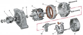
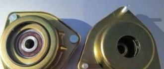
Design Features
VAZ 2109 cars can be equipped with two models of generator units. These are 37.3701 and 9402.3701.
Description of the structural elements of the first:
- 1 — clamping fitting;
- 2 - bushing;
- 3 - buffer fitting;
- 4 — rear cover of the unit;
- 5 - bolt fixing the rectifier device;
- 6 - the rectifier unit itself;
- 7 - valve of this device;
- 8 - capacitor component;
- 9 — rear bearing element of the rotor shaft;
- 10 — slip rings;
- 11 — pulley of the rotor device;
- 12 - brush connected to terminal B of the regulator;
- 13 — contact 30, necessary for connecting energy consumers;
- 14 — contact element 61 of the generating set;
- 15 - brush connected to output Ш on the control mechanism;
- 16 - contact B of this element;
- 17 — the voltage regulator itself in the on-board network;
- 18 — pin for fixing the generating set to the tension bar;
- 19 — impeller;
- 20 - shaft;
- 21 — washers for fixing the bearing device;
- 22 - thrust ring;
- 23 — front bearing element of the rotor device pulley;
- 24 — rotor winding;
- 25 - pole piece of this device;
- 26 - another winding;
- 27 — stator mechanism;
- 28 — front cover of the generator unit.
Diagram of device model 37.3701
Design of unit 9402.3701:
- 1 — protective casing of the device;
- 2 — contact B+ for connecting the electrical equipment of the machine;
- 3 - capacitor device;
- 4 - common contact of additional diode elements. It connects to the D+ output on the control fixture;
- 5 — fixing device for positive diodes of the rectifying mechanism;
- 6 — clamp for negative diode elements;
- 7 - positive diode;
- 8 - negative element;
- 9 — voltage regulator in the machine’s electrical network;
- 10 — rear cover of the generating set;
- 11 — coupling bolt;
- 12 — front cover of the generating set;
- 13 - stator winding;
- 14 - thrust ring;
- 15 — front bearing element of the rotor mechanism shaft;
- 16 - shaft;
- 17 - nut;
- 18 — shaft of the rotor mechanism;
- 19 — cone-shaped washer;
- 20 - regular washer;
- 21 — pole pieces of the rotor mechanism;
- 22 — core of the stator device;
- 23 - bushing;
- 24 — winding of the rotor mechanism;
- 25 — rear bearing element of the rotor pulley;
- 26 — bushing of the bearing element;
- 27 — slip rings;
- 28 — brush assembly holder;
- 29 — contacts of the stator mechanism winding;
- 30 - additional diode element;
- 31 - common contact D.
Design of the generator 9402.3701
Carburetor power units are equipped with devices model 37.3701, and injectors - 9402.3701. These units are similar in design; they are synchronous AC motors. They are equipped with a built-in rectifier unit based on silicon diode elements. And the voltage regulator in them is electronic.
On vehicles built before 1996, 37.3701 models used separate adjusters and brush holders. In such devices, the voltage from pin 30 was supplied to pin B. In later versions, this parameter is supplied to pin B, since B is absent.
Attention!
Regardless of the model of the VAZ 2109 generator, you must always remember one important rule: the minus of the battery must always be connected to ground, and the plus to the generator terminal. If connected incorrectly, increased voltage will be caused through the valves and they will be damaged.
It is also prohibited to turn on the generator without a battery, as this will cause a short-term overvoltage at the generator output, which will damage the regulator and, as a consequence, cause malfunctions of electronic devices in the vehicle network.
How to check for serviceability?
Before diagnosing problems with injection and carburetor cars, you must start the engine and let it run for a few minutes. Then, pressing the gas pedal, you need to increase the number of crankshaft revolutions to 3 thousand/min.
To create a simulation of driving in normal mode, enable:
- driving lights;
- rear window heating systems;
- stoves.
Diagnostics with a multimeter:
- The tester is used to measure the voltage at the battery terminals. This parameter will be 13.2 volts in model 9402.3701 and 13.6 V for 37.3701. If, during diagnostics, without removing the voltage at the battery terminals, the obtained value turns out to be different, this indicates a break or short circuit in the windings of the device. The voltage regulator and brush assembly may also fail. Sometimes the problem is oxidation of the contact components of the field winding.
- To ensure that the regulatory mechanism is working, all energy consumers are switched off. Only the high beam optics remains switched on, after which the voltage measurement procedure is repeated. This parameter should be in the range from 13.2 to 14.7 volts for model 94.3701. In the 37.3701 electric generator, the resulting value will be from 13.6 to 14.6 V.
- If the control element on model 9402.3701 is removed, it can be checked by connecting a light source to the brush mechanism. In particular, between its elements. The lamp should be rated at 1-5 watts and 12 volts. The DC power supply is connected to the D+ pins and device ground. Diagnostics is performed first by activating the voltage at 12 volts, and then at 15-16 V.
- In the first case, the light source should work, but in the second, it should not. If it is activated when 12 and 15 volts are supplied, then a breakdown must be looked for in the regulatory device. If there is no combustion, the cause should be checked for a break or broken contact between the brush elements and the terminals of the device. The regulator itself is changed to restore the generator's functionality. To test the device 37.3701, the light bulb is connected to contacts B and C, this is a plus, as well as to ground.
- Checking the valves of the rectifier device is carried out by disconnecting the cables from the battery, generator unit, and also the regulator contact. The positive terminal from the battery is connected through a light source to the B+ output on the generator device 9402.3701. If this is model 37.3701, then it must be connected to output 30. The negative contact is ground, connected to the housing. If, as a result of the actions performed, the light source started working, then the problem is a short circuit (in both blocks).
- Diagnosis of a similar problem on positive valves is carried out by connecting the positive contact of the battery to the B+ output (for model 37.3701 - contact 30). The connection is made through the light source. The negative contact goes to the output of the phase winding of the stator mechanism (you can connect to any). The inoperability of one or more positive valves will be indicated by activation of the light bulb.
- The procedure for diagnosing a short circuit on the negative contacts of the element is performed by connecting the positive terminal of the battery to the phase winding of the stator mechanism. There should be a light bulb on the electrical circuit, and the negative terminal goes to the housing of the generator set. If the lighting device lights up, this indicates damage to the negative valves or a short circuit of the stator mechanism to the body of the automobile electric generator.
- To prevent short-circuiting of the windings, the assembly is dismantled from the machine, after which the elements are disconnected from the regulator and the rectifier unit. Using a light source or an ohmmeter, parts are checked for short circuits. The valves of the generator device can be diagnosed with a tester; this does not require connecting a battery or a light bulb.
- To check additional diode elements, the positive terminal of the battery is connected to output D through a light source. In model 37.3701, the connection must be made to pin 61. The negative terminal goes to the output of one of the phase windings of the stator device; you can use a screw to secure the rectifier assembly. If the light source lights up, this indicates damage to the diode elements.
- To determine whether the valves are broken, you need to check the output current; this parameter should not fall as a result of the load. But such a problem may be caused by damage or short-circuiting of the windings of the generator unit.
- To diagnose each diode element, you will need a tester or test light. To do this, the rectifier assembly will have to be dismantled. If this device breaks down, it must be replaced as an assembly. It is possible to replace individual valves, but the main elements require re-pressing in the holding device. Performing this operation requires caution and skill from the car owner.
The windings of a stator or rotor mechanism can only be diagnosed using a flaw detector or electronic oscilloscope; the test consists of monitoring voltage curves.
The “Avto-blogger” channel described in detail the procedure for examining a car’s generator unit.
Possible faults
If the node does not work or functions incorrectly, you need to find the cause of the problem:
- When the ignition is activated, the indicator light on the dashboard does not light up. Perhaps this symptom was caused by a faulty fuse. The problem may be damaged wiring. It is necessary to check the electrical circuits and safety devices. Wiring testing is carried out using a tester.
- The LED indicator on the device does not light up, but the battery is discharged, all other control devices are working normally. A possible problem is a short circuit of the diode elements on the bridge or poor contact on the excitation winding. The cause of the problem may be a malfunction of the relay, failure of the brush mechanism, or damage to the wiring from the generator to the dashboard. All failed components can be repaired or replaced yourself.
- The battery indicator light on the dashboard lights up when the engine is running, the battery may be overcharged. It is necessary to diagnose the regulatory device; the problem may lie there.
- When the car engine is running, the battery indicator lights up too brightly or only at 50%. It is necessary to diagnose the drive belt; the problem may be that it is worn out or weakened. To eliminate the malfunction, the belt must be tightened or replaced. The reason may be a short circuit of the stator winding to ground or damage to the electrical circuit. Sometimes the reason lies in faulty diodes or disconnection of the rotor mechanism from the slip rings.
- A whistle comes from under the engine hood. The noise may appear when the power unit is started and disappear after a few minutes, or it can be heard constantly. The problem is due to wear on the drive belt. This product must be replaced.
- A strong hum-like noise may indicate a worn generator set bearing. Sometimes this symptom is associated with a short circuit of the stator winding to ground or a short circuit of one of the diodes.
- At night, when the optics are activated, you can see that the headlights burn dimly. But when you press the gas pedal, their brightness is restored to the required level. The voltage regulator device needs to be checked.
Channel “Tora 18” talked about the main malfunctions typical of automobile generator sets.
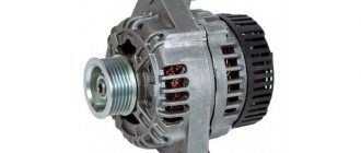
Generator Modifications
On newer VAZ-2109, 21099, 2110 cars, modifications of generators with the designation 94.3701 were installed. Their power is much higher than those used on eights. But the dimensions of the VAZ-2108 generator are the same as those of more modern ones installed on dozens. Therefore, they are interchangeable, but have different characteristics. Here are the differences:
- The current strength of 94.3701 is 80 A, which is 25 A higher than that of the figure-eight unit.
- The voltage adjustment range on the 94.3701 generator is larger.
- The gear ratio between the generator rotor and the engine crankshaft is higher.
Installing a new unit is advisable if a larger capacity battery is used, and in the system of electricity consumers there are a lot of those that have greater power. And if you use standard electric cars, the battery will be discharged and will not have enough current.
How to repair it yourself?
The restoration procedure consists of several stages:
- First you need to dismantle the unit.
- Then it is disassembled, at this stage the unit needs to be repaired.
- After this the assembly is performed.
- At the final stage, the node must be installed and connected.
Required Tools
Before completing the task, you need to prepare:
- vice;
- removable tool for bearing devices;
- set of wrenches;
- screwdriver set.
Removing the generator
The dismantling procedure is performed as follows:
- The cables are disconnected from the generator set. They are usually made in red insulation and include 2 groups of conductors. One of them consists of two cables and is fixed with a nut to a bolt on the rear wall of the unit. The second group includes one cable and is connected to the terminal of the generator device via a contact element. It is also located on the back wall of the unit.
- To remove the generator unit from the power unit, you need to unscrew two nuts and a screw. First, the fastening element installed on the drive belt tensioner bar on top of the unit is unscrewed. Then the screw is unscrewed, which secures the part itself to the engine block of the machine, this element is dismantled. At the final stage, the nut is removed from the screw securing the bracket to the internal combustion engine.
- The fixation part is located at the bottom of the power unit, directly under the generator set. After the nut is removed, the drive belt must be removed from the shaft.
- The screw securing the assembly must be pushed to the left so that it comes out of the bracket. The element is pressed all the way into the vehicle body or into the mud shield of the unit.
- Then the two screws located on the right wheel side are unscrewed. They fix the dust protection of the generator set to the car body.
- If the bolt rests on the elements of the machine body, apply a little pressure to the motor. At the same time, the fastening part is removed.
User Sanya Kiselev spoke in detail about the procedure for dismantling the installation from the Nine engine.
Disassembly and repair
After the unit has been removed, all parts are dismantled and the VAZ 2109 generator is restored to functionality:
- Using a 19mm wrench, loosen and unscrew the nut on the rotor pulley. It is used to fix the impeller. To perform this task, the generator unit must be clamped in a vice. Using a screwdriver, the impeller is held from turning. Using a wrench, unscrew the nut counterclockwise.
- The impeller of the device is fixed with a pin. After dismantling it from the pulley, it is necessary to remove this element and put it aside; it cannot be lost. When unscrewing the nuts, it is recommended to sketch the location of the components.
- Then the generator unit is turned over with the back cover up. Using a size 8 wrench, unscrew the four nuts.
- The pins are removed and the front part of the device body is dismantled. The front bearing element is also located here; it is fixed using plates. To dismantle them, you need to unscrew the nuts that secure the elements.
- Using a special puller, the bearing device is removed from the landing site. If you don’t have a tool, you can use a hammer and a mandrel of the appropriate size. The use of a wooden board is allowed.
- The spacer sleeve is removed from the rotor mechanism pulley.
- This unit is removed from the rear cover of the generator device.
- The leads of the stator winding are disconnected from the rectifier. To do this, you need to unscrew the nuts that secure them. After dismantling the fastening elements, the bolts are unscrewed. They record the conclusions themselves.
- Insulating pads are located on the bolts. The stator winding must be removed from the unit housing.
The next step is to remove the diode bridge; this requires the following steps:
- Use a wrench to unscrew the nut that secures contact number 30.
- Next to this pin there is a block with a plug. This element must be dismantled. But you should first release the fastener using a small flat-head screwdriver.
- The latch is disconnected from the inside. Then the block with wires is pushed inside. The plug should remain on the cover. The diode bridge is dismantled from it.
- The next step requires a vice. The rotor mechanism must be clamped into the equipment so that the rear bearing device is located on the top.
- Using a puller, the part is dismantled. To do this, you need to put the tool on top of the assembly and pull the bearing element off the pulley.
Unscrewing the impeller of the generator unit Disconnecting contact 30, connector and dismantling the diode bridge Removing the bearing device from the pulley
After disassembling the elements of the generator unit, replacing the failed components:
- To change bearing parts, you need to check the markings of the elements. Similar spare parts are purchased at the auto store. Even if the bearings are visually intact, it is recommended to replace them. The parts are not interchangeable, so when purchasing, be sure to follow the markings.
- The same goes for the diode bridge. The markings are rewritten from the part, only after that the spare part is purchased. If there is visible damage to this device or metal oxidation has occurred, the unit must be replaced. It is fixed to the generator housing with four nuts. The diode bridge is located at the back, on the inside.
- A visual diagnosis of the front cover of the generating set is carried out. If there are cracks or other damage, the casing must be replaced. When performing visual diagnostics, it is important to pay attention to the fastening elements.
- The diameter of the seat for the bearing parts in the front cover is measured. If the socket for their installation is more than 4.2 cm in diameter, the cover must be replaced.
- Then a visual check is made of the rear of the unit. If there is damage on it in the form of cracks, it must be replaced. Wear or breakage of the seating area under the bearing element is not allowed. If such damage occurs, the cover must be replaced.
- Visual diagnostics of the internal surface of the stator device is carried out. Scratches and other defects resulting from touching the anchor are not allowed. If wear is detected, the bearing elements or the generator set cover are replaced.
The winding of the dismantled rotor mechanism is checked, the task is carried out as follows:
- It is necessary to visually inspect the slip rings. These elements must be replaced if defects are found. We are talking about signs of wear, scuffs, scratches, etc. In principle, the rings do not need to be replaced if the damage is minor. But then they will have to be sanded, for this you will need fine-grained sandpaper.
- If damage to the elements cannot be removed with sandpaper, you can try turning them on a lathe. When using the equipment, it is necessary to remove a minimum layer of metal and then sand the surface.
- Using a tester, the resistance value of the winding of the rotor mechanism is checked. To do this, the device must be connected to slip rings. If the diagnostics show that the resistance tends to infinity, this indicates a break inside the winding. To correct the problem, you will need to replace the rotor mechanism.
- Using a test lamp, a diagnosis is made of the absence of a short circuit in the winding of the anchor device on the housing. To do this, you need to activate the light source by connecting it to the battery. One contact is connected to the body of the anchor device, and the other is connected to each ring in turn. The indicator light should not light up when the rotor is operational. If it is activated, this indicates a short circuit in the winding, then the armature will need to be replaced.
Vyacheslav Lyakhov spoke in detail about performing diagnostics, as well as repairing the unit in the VAZ 2109 car.
Generator assembly
If you managed to disassemble and repair the unit, then after completing the work you will need to put it back together:
- The rear bearing device is installed at the landing site, on the shaft. A wooden board and a hammer are used to complete the task. The bearing is carefully driven in so as not to damage the part. To do this, just hit it several times.
- If the diode bridge was dismantled, it must be reinstalled. The device is located in the back cover of the case.
- The protective casing is then installed on the anchor device so that the bearing element is completely seated. To simplify the action, you can use a hammer. Light blows on the cover clog the bearing; it must be placed on the pulley. The same part installed on the front cover is replaced and fixed using plates.
- Then the generator device is dismantled from the vice. Before installing the front cover on the assembly, the spacer ring is mounted on the pulley. This part should be located between the thrust recess and the front bearing device.
- The cover is installed from the front, the stud nuts are tightened using the crosswise method. This will ensure more uniform tightening of the fastening elements.
- The stud is installed in the recess on the shaft of the anchor device. Then the impeller is installed, the element is clamped with a nut.
- At this point, the assembly procedure for the generator device can be considered complete. All that remains is to install the voltage regulator with brushes at the landing site.
Evgeny Bragin described the assembly procedures for the “nine” unit, indicating all the nuances of this process.
Installation and connection
Installation of the generator unit is carried out in the reverse order; when performing this task, it is important not to forget to connect the wire to the control device:
- A fixation bracket is screwed to the installation. A wrench is used.
- The bracket is then screwed into place with the generator set. When performing this task, you do not need to tighten the nut all the way.
- Self-tapping screws are used to secure the unit's dust protection.
- The drive belt is being installed on the generator set pulley.
- The tensioning element strip is being installed.
- The drive belt is tensioned. When performing this task, it is important that the deflection of the product is about 1-1.5 centimeters. When tightening the belt, it is necessary to tighten the nut on the tensioner bar. Then this element is clamped on the bracket until it stops.
After the installation is completed, you need to connect the terminal blocks to the generator device. When performing the task, you need to make sure that the clamps are disconnected from the battery. There should be a total of three wires connected to the unit. Paired cables are secured with nuts to a stud located on the back cover. A male connector must be installed in a female connector.
Then the terminal clamps are installed on the battery, and the power unit is started. The generator unit supplies the voltage required for full operation of all machine devices.
To be sure that the unit is working properly, you need to use a voltmeter to diagnose the voltage that the unit produces.
Generator set connection diagram
Difficulties in reworking
Since the work is quite labor-intensive and takes a lot of time, we recommend performing the steps in stages. The quality of components and their assembly play an important role during work. Beginners may have difficulty securing some elements, so it is better to call for help from a familiar car service specialist or a person who has replaced a carburetor with an injector before.
Replacing a carburetor with an injector will require you to be careful and careful. You will need to replace a lot of parts, and this is quite difficult for a beginner to do. But if you wish and strictly follow the instructions, you can perform a really serious modernization of your car and save a lot on car service costs.
Welcome! A generator is an integral part of any car, the generator supplies current to the on-board network, which is generated when the generator pulley rotates. Thanks to this, the battery does not have to work constantly and after starting the engine, it stops supplying current to the on-board network of the car, and only one starts supplying it. generator, but there are cases when it fails (Over time, this usually happens because sand and other types of dirt get into the generator, or the generator can simply burn out due to a short circuit) and it becomes impossible to drive a car, since One battery turns on, and when it is completely discharged, the car will stall and simply won’t go anywhere, so the generator needs to be changed when it becomes unusable or repaired (we will still touch on the topic of repairing the generator in this article).
Note! To change the generator, you don’t need a lot of time and tools, it will be enough to stock up on: Several keys, one of which should be “17” and the other about “19” and a pry bar or something like it (A stick, for example)!
Summary:
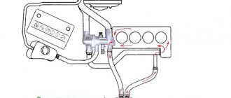
Where is the generator located? It is located between the TV and between the engine, when you open the hood you will immediately see it, but it will only be attached a little differently, not as shown in the photo, but the location will be exactly the same, for clarity it is indicated in the photo below with a red arrow.
When should the generator be replaced? 1. You can understand whether it provides charging or not at all in two ways, which one you choose is up to you, we usually recommend the first method to all those people who ask us a question about how to check the generator for serviceability, and it is as follows: You can buy a multi-meter at any auto store (It is available almost everywhere), the Chinese ones are quite cheap (About 300 rubles), You do not work at the station and are not an electrician, so this multi-meter will be quite enough (If you want, of course , you can get it for more expensive), in general, you buy this device and turn on the Voltmeter function on it, after which the leads coming from the multi-meter are connected to the battery (see photo below) and pay attention to the device (If the battery is working and charged, then it will have to give out at least 12.5 Volts, if it gives out less than 12, then it needs to be charged), now the next step is to start the car and the wires coming from the multi-meter are connected in exactly the same way as before (the function should still be turned on on the device Voltmeter) and the device is looked at again, the readings of the device will definitely increase, but if they fall, then the generator is not working properly and does not charge the battery (Also look at the charge lamp, see the small photo, if it is on and the readings of the device with the engine running gradually fall, then the generator is 100% faulty).
2. Now let’s talk about the second method, let us immediately warn you that it is free, but it can have a very bad effect on the generator, this is how it is done, start the car and the choke is pulled out (it is generally not recommended to do this on an injector), so after the choke is pulled out ( Halfway somewhere, so that the engine runs at 1500 rpm) and the car works for a while (A minute is enough, even less), the minus terminal is removed from the battery, and after removal the car will definitely have to continue its work (This indicates that the on-board network the car, and the ignition is powered from the generator and not from the battery), but if it stalls immediately, then the generator does not work (The brushes are worn out or the diode bridge is burned out), in general, such a generator will have to be removed and checked for serviceability (By the way, about how repair the generator, read the article: “Repairing the generator on a VAZ”) but there is one big minus, if the generator is not working correctly (This happens because of the brushes) but it still works, then the car will not stall and because of this, it will always the car's battery is discharged and therefore, to find out more accurately whether it provides charging and whether it gives it as it should, you can only find out with a multi-meter and by the way, if you buy this device, you will not regret it, since it will be very useful to you in the future .
Safety precautions when working
Nuances that must be taken into account when repairing a VAZ 2109 generator:
- All control and adjustment work related to diagnosing the unit with the engine running must be carried out in a ventilated area or outdoors. If it is a garage, it is recommended to open the doors or provide good ventilation.
- Before carrying out the task, you need to button up your sleeves if the work is performed in a shirt. All hanging ends of clothing should be removed to prevent them from getting caught on the operating pulley.
- To carry out repairs, a specialized tool is used.
- The generator must not be allowed to fall after it has been removed during transportation to the machine. This can lead to complete failure of the unit.
- Repairs should only be carried out using serviceable, clean and oil-free tools.
- If the nuts are rusty and difficult to unscrew, it is recommended to treat the elements with kerosene or WD-40 before turning them out. Dismantling is carried out with preliminary tapping with light blows of a hammer.
- The vehicle is inspected using a 36-volt light bulb. If the diagnosis is performed in a ditch, a 12 V light source will be required. It is important that the light bulb is equipped with a safety net.
Features of work
What might a faulty unit look like, how to remove and disassemble the generator, how is it rebuilt? If the device does not charge the injector or carburetor of a VAZ 21099 or 2109, first of all, let's look at the features of its functioning, namely the power circuit.
Generator power circuit
Node power circuit
So, what does the scheme include:
- The VAZ 2109 generator itself.
- Negative diode.
- Additional element.
- Positive diode.
- The warning light also informs the driver that the battery is low.
- Vehicle dashboard.
- Voltmeter.
- The fuse box is installed in the engine compartment under the windshield opposite the driver's seat.
- Resistor elements installed in the same block.
- Ignition relay "nine".
- The castle itself.
- Battery
- Capacitor device.
- Winding.
- Generator voltage regulator relay installed in the engine compartment.
It should be noted that the connection diagram for the VAZ 2109 generator is relevant for all cars with front-wheel drive of the eighth line - both 2108 and 21099 (the author of the video is Semyon Pedan).
Repair costs
The approximate cost of spare parts is shown in the table.
| Name | Price, rub |
| Price of a set of bearing elements | Around 150 rubles. |
| Generator diode bridge | 200 rub. |
| Charging relay | About 150-200 rub. |
| Removal tool for bearing elements | Around 100-200 rubles. |
| Prices are relevant for three regions: Moscow, Chelyabinsk, Krasnodar. | |
The practical part is removing the generator, disassembling it, repairing it and reinstalling it.
Due to the fact that the generator is located under the hood of the car, it is necessary to turn off the engine, turn the steering wheel to the right all the way and open the hood. The electric generator on VAZ 2108 - 15 cars is installed in front of the engine, in the lower left corner of the engine compartment, between the engine and the cooling radiator.
Before dismantling the generator, it is necessary to disconnect the ground from the battery, i.e. negative contact.
Replacing VAZ generator brushes
Before removing the generator itself, in order not to do unnecessary work, we remove the charging relay from the generator housing and check the production of the generator brushes. The charging relay is installed in the rear of the generator housing, and is attached to it with two bolts. To unscrew them you will need a Phillips screwdriver. When unscrewing the bolts, be careful not to drop them on the crankcase guard, otherwise getting them out of there will be one big problem.
To remove the relay, you need to disconnect the wire, the “female” contact. After removing the charging relay and visually inspecting the brushes, we decide to purchase a new generator voltage regulator relay or reinstall the dismantled one, depending on the wear of the brushes. For their normal operation, a brush length of at least 4 cm is required. Now we proceed directly to removing the electric generator from the engine.
- We disconnect the wires from the generator - as a rule, they are red and consist of two groups of wires, red. One group consists of two wires and is attached with a nut to a bolt on the rear wall of the generator. The other group consists of one wire and is connected to the generator terminal via a male-female contact, also on the rear wall of the generator.
- To remove the generator from the engine, you need to unscrew two nuts and one bolt in the following sequence: unscrew the nut attached to the generator belt tensioner bar (at the top of the generator), unscrew the bolt securing the tensioner bar to the engine block and remove it. The last step is to unscrew the nut from the bolt securing the generator bracket to the engine block.
- The generator mounting bracket is located at the bottom of the engine block, directly below the generator. After unscrewing this nut, you need to remove the generator belt from the generator pulley itself.
- The generator mounting bolt should be pushed to the left, out of the bracket, until it stops against the body shell or the generator’s mud protection.
- On the right wheel side, you need to unscrew the two screws that secure the dust protection of the generator to the car body.
- If the generator mounting bolt still rests against any body parts, you should press on the engine with one hand, and at the same time pull out the bolt with the other hand.
Now your generator is completely disconnected from the engine, and you can begin to disassemble and repair it.
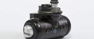
Removing the generator pulley
To do this, we stop it from turning with a screwdriver and unscrew the nut securing it with a 19 mm spanner. The tightening torque is large, so it is better to use a wrench with a long handle.
Removing generator pulley 37.3701 for VAZ 2108, 2109, 21099 cars
Then we remove the following parts: nut, washer, pulley with impeller, segment key.
Separate the halves of the generator housing
First, we mark their relative positions (by placing marks on both parts). Using a 10 mm wrench (it’s more convenient to use a socket or socket wrench), unscrew the four nuts of the coupling bolts (there are engraving washers under the nuts).
Pull out the bolts. Remove the front part of the generator. Remove the rotor from the back of the generator. If it cannot be removed, you can tap it with a soft metal drift through the window under the voltage regulator, or by screwing a nut onto the thread of the shaft and holding it in a vice, with a sharp upward movement, pull the back cover into the shaft. The bearing remains on the rotor shaft. If necessary, we dismantle it with a puller and press on a new one (See “Replacing generator bearings”).
Disconnect the stator
Using an 8 mm wrench (it’s more convenient to use a socket or socket wrench), unscrew the three nuts securing the stator terminals to the diode bridge. We remove it from the back cover of the generator by prying it with a slotted screwdriver or hitting it with a hammer.
When is it time to repair a generator?
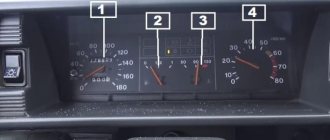
1. Any instrument cluster has a battery charge indicator (indicated by a red arrow, using the example of an instrument cluster from a high panel). When the generator stops supplying charge to the battery, this indicator lights up. When the ignition is turned on, it should light up, but when the car starts, it must go out. Otherwise, the generator does not produce current and needs to be inspected. It happens that the battery runs out quickly, and the indicator lamp does not light up at all. In fact, you can’t trust it 100%; sometimes the generator produces a very weak current, insufficient for a light bulb. This situation leads to the fact that literally in 1 week the battery is completely drained and you have to put it on charge. We recommend periodically checking a working battery.
2. You will need a multi-meter with the voltmeter function enabled. Measure the readings given by the generator to the battery (the procedure is demonstrated in detail in the video below). After you start the car, the voltage at the terminal will most likely be about 12-13 Volts and will gradually increase. Don't have a voltmeter? There is an alternative way to check, but it causes damage to the diode bridge (we do not recommend using this method on fuel-injected cars; it is better to stock up on a multi-meter):
- start the engine and let it run for approximately 2 minutes;
- apply gas and pull out the choke so that the engine reaches about 2 thousand revolutions;
- Disconnect the negative terminal from the battery.
If the car works, everything is fine with the generator, put the terminal back. The car stalled - the generator has become unusable and needs to be replaced or repaired. But! It happens that the generator gives a charge, but it is too weak (around 12 Volts), which is why the battery quickly runs out (the car will not stall after removing the terminal from the battery, so this method does not always work).