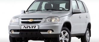
The Chevrolet Niva SUV, produced by VAZ, is popular among car enthusiasts due to its good cross-country ability. To overcome muddy roads, steep climbs, and various obstacles, it needs impeccable engine coordination. One of the negative factors that negatively affects the performance of a car’s heart is detonation. Its increased level creates strong vibration of the vehicle, leading to increased wear and breakdown of internal engine parts. To avoid this, a knock sensor is used on a Chevrolet Niva car, which monitors and normalizes the fuel combustion process in the engine, eliminating potential malfunctions.
Knock sensor and its purpose
Knock sensors are used in gasoline-powered vehicles that have an injector built into their circuitry. They help reduce fuel consumption and allow engine power to be maximized.
The appearance of detonation in a Chevrolet Niva (which can also be attributed to the Niva 21214 SUV, a model similar in characteristics) is possible under increased loads. Heavy uphill climbing and swampy terrain create conditions for the power unit to fail. This occurs due to premature ignition of the fuel mixture in the combustion chamber. The sensor neutralizes the imbalance between the moments of fuel injection and combustion, eliminating unpleasant metallic knocks.
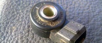
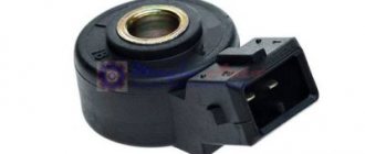
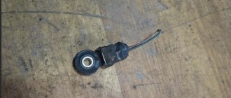
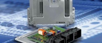
The appearance of the knock sensor (DS) on a Chevy Niva car is quite simple. Motorists say: “You will find it easily!” This is a small round element with a mounting hole in the center for a bolt, and an electrical connector attached to it. The DD is connected to the electronic control unit (ECU) and consists of:
- frame;
- piezo crystal plate;
- electrical connector.
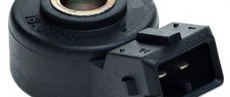
Knock sensor
The principle of operation of the sensor is that a piezoelectric element located inside its housing converts mechanical vibrations from detonation into an electrical signal, which is supplied to the ECU. The frequency response of the signal has a certain meaning during standard operation. If its parameters deviate from the specified ones, the electronic unit will detect the discrepancy and adjust the engine operation. Thus, the DD on Chevrolet Niva and Niva 21214 is designed for timely detection of emerging detonation and its prevention. This significantly increases the service life of the vehicle.
Sensors and the nuances of replacing them with your own hands on the famous Niva
Elements such as the VAZ 21214 speed sensor can be replaced without much difficulty. It seems possible to quickly change this and other system parameter determinants and regulators with your own hands. You will learn how to do this from our article.
On products of the domestic automotive industry such as UAZ and Niva, various sensors are needed to transmit information to the dashboard. Also, some of them perform additional functions. And each has its own characteristics of dismantling and installation.
Detonation
Knock detector and wire terminal
The phenomenon of detonation is the explosive combustion of fuel in an engine due to glow ignition. SUVs like the Niva suffer from this problem quite often.
A piezoceramic element is installed in the area of the cylinder block - this is the knock sensor. Its function is to transmit a signal to the controller, which will automatically adjust the ignition timing. Thanks to this, the phenomenon will be eliminated. Also, thanks to the sensor, the controller provides a light indication of an emergency situation on the instrument panel.
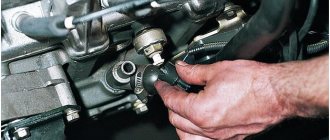
The Niva knock sensor can be removed using only a screwdriver and a 13mm wrench. Remove the block by pressing the lock, then unscrew the bolt with a wrench.
Camshaft
This part is required to determine the angular position of the timing mechanism in accordance with the crankshaft. Information from it enters the engine control system. It is used to regulate fuel injection and ignition.
Experts recommend changing this part every 100 thousand km or 5 years. This is due to the fact that it is subject to constant temperature changes, which negatively affects the operation of the sensor. Unfortunately, it is quite difficult to independently determine its malfunction; this requires an oscilloscope and other equipment.
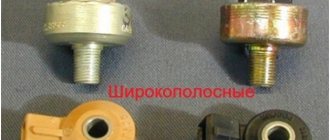
1. Broken knock detector 2. Installation of knock detector 3. Speed detector
Speeds
The Niva 21214 has an electronic, also known as cableless, speed sensor. Its main function is to transmit information about the vehicle speed to the speedometer. You will find this parameter finder on the gearbox, on the rear transfer case cover.
To replace it, you will need to get to the car from below, using a hole or other method.
- Squeeze out the plastic clip and remove the terminal with wires.
- Then use a wrench to unscrew the device. If it doesn't come off, there's no need to pull. The problem is corrosion; WD-40 solvent will help to cope with it; you need to apply it to the connection and wait.
- Install the new part in the reverse order.
Idle move
RXX Niva
The idle speed sensor, also known as the regulator (IAC), is located on the throttle valve.
- A block with wires is connected to it, which is removed by releasing the latch. Then you need to unscrew the two bolts using a Phillips screwdriver.
- Then you can simply pull out the sensor.
- When installing, perform the same steps in reverse order.
Fuel level
This sensor is required to display information about how much gas you have left. In some cases, it becomes unusable and needs to be replaced.
First, you'll need to remove the floor mats and rear seat to gain access to the hatch where the gas tank is hidden. The hatch is a sheet secured with 12 screws. Unscrew them and remove the hatch completely by lifting it up and sliding it forward.
Now you can see the gas tank and fuel pump. Remove the connector from the latter by placing a rag under the draining gasoline. It is better to dismantle by draining 5-7 liters from the tank if it is full.
The sensor is installed in a recess at the top of the gas tank. Disconnect the wire block by pressing the plug, and then remove the sensor itself. Install in reverse order.
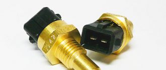
DTOZH
Installation of DTOZH
This sensor is used to determine the coolant temperature. Also, it is its readings that are used automatically to turn on the fan. Thus, the DTOZH and the fan switching sensor are one and the same thing on Niva cars. But on other machines these may be two different parts.
You will find it on the cylinder block. To remove, first drain the coolant. Then, disconnect the wire. The sensor itself is unscrewed with a spanner set to “21”. When installing a new regulator, lubricate its threads with sealant and perform all steps in reverse order.
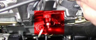
About the location of the knock sensor
An important point for diagnosing an accurate signal is the location of the measuring element. The DD is located where the source of detonation is located - on the engine. It is bolted directly to the cylinder block in the center so that the distance between it and the cylinders (first and fourth) is equal. This will make it possible to identify any detonation knocks that occur during engine operation.
Knock sensor location
Another way to find the DD under the hood of a car is to follow from the ECU to the sensor along the wire connecting them, laid in a corrugated tube.
Principle of operation
The sensor is based on a piezoelectric element - a plate that, under the influence of vibration, generates electrical impulses. This is called the piezoelectric effect, and the device operates on its principle. Moreover, the voltage at the output of the device depends on the oscillation frequency when the engine block vibrates. In other words, as vibration increases, the stress generated by the plate also increases.
When the engine shakes, the knock sensor, the symptoms of which will be discussed below, begins to generate a small voltage. This signal immediately goes to the control unit. The latter contains an algorithm by which the microprocessor determines what to do in a particular case. It analyzes the level of vibration, and then makes adjustments in the right direction: first it sets the ignition timing, and then changes the quality of the mixture (ratio of air and gasoline) to the current settings.
About the malfunction of the knock sensor
When the sensor fails, signs of a sensor malfunction are, first of all, the inclusion of a light indication on the “Check-engine” dashboard and detonating metallic knocks in the engine.
Instrument panel with illuminated “Check-engine” icon
Warning symptoms in vehicle operation: decreased engine power, increased fuel mixture consumption, and the appearance of smoky exhaust. The manifestation of the detonation effect on a Chevrolet Niva is an indicator that cannot be taken lightly. The item must be replaced as soon as possible. Otherwise, the engine itself will have to be repaired. To do this, you will need to make sure that it is the DD that is in a faulty state, because the reasons for the lack of a signal may lie in the following:
- lack of contact in the connector;
- broken wires;
- Damage to insulation or braided shielding.
You can read below about how to check the knock sensor yourself. It's not difficult at all.
Fault detection
Even if you don’t have a deep understanding of the internal workings of your car’s mechanisms, you have the power to ensure their smooth operation. Who, if not you, can first of all detect the instability of the functioning of some nodes. Considering that trips with individual malfunctions can have serious consequences, any driver must have at least a minimum knowledge of the principles of operation of the parts of his car, know their service life, and be able to identify and eliminate trivial problems, regardless of the make and model of the car.
Most modern cars operate using a mass of sensors, the malfunction of which can mainly be determined through computer diagnostics on service equipment. However, some sensors make themselves felt quite clearly, and with due care of the driver it will not be difficult to determine which one has failed.
Self check
It is only possible to make sure that the DD is not working by testing it with a multimeter or voltmeter. To do this, the sensor will need to be removed from its seat by unscrewing the mounting bolt using a 13mm wrench. Then disconnect the element from the connector block.
Checking the sensor with a multimeter
The verification is a simple procedure. Having connected a multimeter/voltmeter to the sensor contacts, the measuring device should be set in DC voltage measurement mode. Then, using light taps on the piezoelectric element, monitor the tester readings. A working DD will produce voltage surges of up to 0.2 volts. If the reading remains unchanged, then the sensor should be considered inoperative and replaced.
Throttle position sensor - TPS.
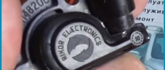
The function of this sensor is to provide information to the brain about the position of the gas pedal and the degree of throttle opening. The TPS contains electromechanical parts, that is, a potentiometer. This means that after some time it wears out and the sensor dies. In Russia there are about 10 companies producing this sensor
But I want to draw the reader’s attention to the so-called non-contact (inductive) TPS. It is made by one company that used to be a “mailbox”
My experience has shown that the sensor in their “non-contact” design is virtually eternal. This is exactly what is shown in the photo.
Replacing the sensor
Reinstalling a faulty sensor should not be delayed. In terms of cost, it is relatively inexpensive. Its price, for a Chevrolet Niva car, is approximately 1000 rubles; alternatively, you can purchase a cheaper analogue.
The knock sensor is installed in the reverse order of removal. That is, it is attracted by a bolt to a seat, which is located on the cylinder block and is connected by a wire to the computer through a connector block.
With the new knock sensor, the Chevrolet Niva SUV will be able to easily overcome steep climbs and off-road terrain.
Engine control system VAZ-21214
Connection diagram of the VAZ-21214 engine management system with central fuel injection under US-83 toxicity standards with controller 21214-1411010 (EFI-4 type) on VAZ-21214 vehicles: 1 - “CHECK ENGINE” control lamp; 2 — instrument cluster (fragments); 3 — electric fans of the engine cooling system*;
4 — electric heater of the intake pipe; 5 — air temperature sensor; 6 — absolute pressure sensor; 7 — coolant temperature sensor; 8 — block connected to the throttle position sensor; 9 — central fuel injection unit; 10 — block connected to the idle speed regulator;
11 — block connected to the nozzle; 12 — diagnostic block; 13 - controller; 14 — knock sensor; 15 — speed sensor; 16 — oxygen concentration sensor; 17 - adsorber; 18 — battery; 19 - main relay; 20 — fuse block of the engine control system; 21 — relay for turning on the electric fuel pump;
22 — relay for turning on the electric fan*; 23 — relay for turning on the electric heater of the inlet pipe; 24 — electric heater protection fuse; 25 — starter activation relay; 26 — ignition relay; 27 — main car fuse box (fragment); 28 — spark plugs; 29 — tachometer; 30 — electric fuel pump with fuel level sensor;
Also interesting: Chevrolet Niva central locking diagram: what to do if the lock from the key does not work, where the control unit and relay are located
31 — ignition module; 32 — crankshaft position sensor; 33 - courtesy light switch, located on the driver's door pillar; 34 — control unit of the automobile anti-theft system**; 35 — status indicator of the car anti-theft system**; A - wire going to plug “50” of the ignition switch;
The order of conditional numbering of plugs in the blocks: a - controller; b — control unit of the automobile anti-theft system; c — indicator of the state of the automobile anti-theft system; g — speed sensor; d — central fuel injection unit; e — electric fuel pump and oxygen concentration sensor; g — ignition module; h - absolute pressure sensor.
Connection diagram of the VAZ-21214 engine control system with distributed fuel injection under Euro-2 toxicity standards with controller 2123-1411020-10 (type MP 7.
0) on VAZ-21214 cars: 1 - warning lamp of the engine control system; 2 — instrument cluster (fragments); 3 — electric fans of the engine cooling system; 4 — courtesy light switch, located on the driver’s door pillar; 5 — status indicator of the car anti-theft system;
6 — control unit of the automobile anti-theft system; 7-coolant temperature sensor; 8 — air flow sensor; 9 — throttle assembly; 10 — block connected to the throttle position sensor; 11 — block connected to the idle speed regulator; 12 - controller; 13 — oxygen concentration sensor;
14 — knock sensor; 15 — crankshaft position sensor; 16 — speed sensor; 17 - adsorber; 18 — battery; 19 - main relay; 20 — diagnostic block; 21 — fuse block of the engine control system; 22 — relay for turning on the electric fuel pump; 23 — relay for turning on electric fans;
24 — main car fuse box (fragment); 25 — block connected to the additional wiring harness*; 26 — ignition module; 27 - tachometer; 28 — electric fuel pump with fuel level sensor; 29 — nozzles; 30 — spark plugs; A - rear wiring harness wire connected to switch 4;
The order of conditional numbering of plugs in the blocks: a - controller; b — control unit of the automobile anti-theft system; in - air flow sensor; g — speed sensor; d — indicator of the state of the automobile anti-theft system; e — electric fuel pump and oxygen concentration sensor; g - throttle pipe; h — ignition module.
Read news about the new Niva
- Clutch adjustment on Niva 21214 - Online reference book to help the car owner - looking for and fixing faults
- How to eliminate vibration of the VAZ-21213 transfer case
- Fuses and relays (location and purpose of fuses and relays) Niva Chevrolet "
- Mud tires for Niva 4x4: radius 15 and 16 - which one is better to install "
- Liquids used and filling volumes Niva VAZ 21213, 21214, 2131 lada 4×4
- Wheel stud M12x1.25x41 2121, 21213, 2131, 21214, 2123 rear
- Niva Chevrolet transfer case: device, connection diagram and how to use?
- How is a CV joint replaced on a Chevrolet Niva?
How does the meter work?
The engine is unable to constantly operate in detonation mode - the cylinder-piston group will collapse very quickly. Therefore, the knock sensor is responsible for detecting the primary shock wave in the chambers and alerting the electronic control unit, which takes further measures to prevent micro-explosions.
There are three ways to reduce the burning rate of the mixture:
- lower the compression ratio (previously, additional gaskets were installed under the cylinder head);
- organize the flash a fraction of a second later, that is, reduce the ignition timing;
- Do not use gasoline with a low octane number and low knock resistance.
Of the listed methods, only one is available to the controller - adjusting the advance angle. When a car owner fills in the wrong or low-quality fuel, a shock wave is formed in the chambers from too rapid combustion. The knock sensor is located outside on the wall of the cylinder block, registers incipient micro-explosions and supplies a voltage pulse to the control unit. The latter reacts and reduces the advance angle - making the ignition late.
The combined actions of the controller and the knock sensor save engine parts, but worsen driving characteristics. After refueling, the car begins to become “dull” and consume more gasoline - these are not symptoms of a faulty sensor, but the result of filling with low-octane fuel and a sign that the meter is working correctly. The problem goes away on its own when you use bad fuel and fill it with quality fuel.
What is a sensor
The cylinder block in the engine has a head containing 1-2 camshafts. Additional equipment in this part includes special blades, the main function of which is to control the intake and exhaust valves. The block also includes a crankshaft, due to which the camshaft itself begins to move.
Three elements may be involved in this process:
- Gears.
- Timing belt.
- Valve train chain.
Operating principle
The rotation position of the camshaft in relation to the current crankshaft position is analyzed during operation of the engine ECU. This is necessary to determine the working cylinder. The camshaft position sensor is responsible for reporting such information. Thanks to the data obtained, the parameters for the further operation of the injectors and spark generation system are adjusted.
The performance of the sensor is influenced by several factors:
- level of harmful emissions;
- motor efficiency;
- savings on fuel costs.
There are currently two types of sensors in cars. These are Hall sensors, or electromagnetic types. They are responsible for transmitting the signal to the internal combustion engine unit.
When inductive sensors operate, an alternating current signal is generated. Identification in this case is simplified; two wires are enough for it. In the case of a Hall sensor, creating a signal requires additional power. Therefore, most often there are three wires to the device
This is important to know when replacing the Niva Chevrolet camshaft sensor
How to make sure the DPRV is working?
The easiest way to check the camshaft sensor is to connect a car scanner or a computer with an installed program corresponding to the make of the car to the diagnostic connector of the car. If the element is faulty, then after starting the engine the device will display the following error codes:
- P0340 – there is no signal from the camshaft position detector;
- P0341 – valve timing does not coincide with the compression/intake strokes of the cylinder-piston group;
- P0342 – the signal level in the electrical circuit of the DPRV is too low;
- P0343 – the signal level from the meter exceeds the norm;
- P0339 – an intermittent signal is received from the sensor.
Since the vast majority of car enthusiasts do not have scanners and laptops with software at their disposal, a more affordable method is practiced - checking with a digital multimeter. Diagnostics is carried out in 3 stages:
- Visual inspection of the wiring and continuity of the circuit for breaks.
- Measuring the outgoing current at the control contact of the DPRV.
- Testing functionality by approaching a metal object.
At the first stage, you need to ensure the integrity of the wiring and reliable contact of the connecting block. Carefully inspect the supply cables for kinks, cracks and melted insulation. Testing the current-carrying conductors and searching for a break is performed with the same multimeter. Don't forget to clean the connector contacts from oxidation.
After checking the electrical wiring, proceed to diagnosing the camshaft sensor itself. Instead of standard alligator clips on the tester, you need to use wires with needles so that you don’t have to be tricky with connecting to the connecting block. Diagnostic work is carried out in the following order:
- Open the hood and look for the DPRV on the cylinder head. Usually the element is placed on the end of the engine or the side wall of the cylinder head next to it.
- Using the vehicle's electrical diagram or data for a specific sensor model, determine the location of the two power contacts and the third wire going to the controller.
- Turn on the ignition and measure the voltage between the vehicle ground and the control contact of the element (on VAZ cars this is the middle wire, marked “C”). Normal multimeter readings are at least 90% of the supply voltage, that is, 12 * 0.9 = 10.8 V.
- If the obtained values are below normal, the sensor is faulty and must be replaced. Otherwise, perform the third stage of verification.
For final diagnostics, the part will have to be removed from the engine. Typically, the element is inserted into a hole in the cylinder head and secured with one bolt. Unscrew it, remove the DPRV and wipe off the engine oil. Do not disconnect the block with wires.
After connecting the multimeter to the middle contact and ground of the car, turn on the ignition again. Bring a steel object (for example, an open-end wrench) close to the end of the element, monitoring the display readings. A working sensor should respond to the approach of metal with a voltage drop to 0.2–0.4 V.
If checking the camshaft sensor with an iron object does not change the tester readings, the DPRV should definitely be changed. When purchasing a new part, keep one thing in mind: even original spare parts can be sold without a thin O-ring. You will have to find and buy it separately or use an old seal, provided that the material is not cracked or “dull.”
Where is the Chevrolet Niva camshaft sensor located and malfunctioning?
To make driving a car quite comfortable and safe, you need the measured operation of its engine. One of the characteristics of its operation will be the camshaft sensor.
What is engine detonation?
Gasoline engines are designed for a certain combustion rate of the air-fuel mixture in the cylinders, corresponding to the compression ratio. When fuel burns too slowly, the engine significantly loses power. If the combustion rate in the chambers exceeds the calculated one, detonation combustion occurs - a microexplosion, accompanied by a sharp release of a large amount of energy in a closed space.
Symptoms of detonation are vibration and loud knocking of the piston pins caused by a shock wave from the combustion chamber. The reason is the use of gasoline with a lower octane number than provided for by the engine design. How does this happen:
- A low-octane combustible mixture, designed for combustion at a pressure of 8–9 Bar (relatively speaking), is compressed by a piston to 12 Bar.
- From a spark, the mixture ignites and begins to burn at high speed. A shock wave is formed, accelerating combustion, which in turn strengthens this wave. Detonation occurs.
- The result is a strong blow to the piston crown, transmitted to the connecting rod and crankshaft. All moving parts of the engine are subject to destructive vibration.
Important! Detonation combustion is often confused with the “pseudodiesel” effect - spontaneous ignition of fuel without a spark at the spark plug electrodes.
The latter occurs due to the formation of additional sources of high temperature in the chambers - a hot layer of soot. Then the mixture ignites itself - from compression and contact with this source. The engine continues to run even with the ignition off.
Location of fuse and relay blocks Lada 4×4
If during the inspection it turns out that the camshaft position sensor itself has failed, then it must be replaced. As a rule, these units are non-repairable, since their body is sealed and cannot be disassembled. The sensor is inexpensive, and the replacement procedure is simple, and even a novice car enthusiast can handle it.
The sensor replacement algorithm is as follows:
- With the engine not running, disconnect the negative terminal from the battery.
- Disconnect the “chip” from the camshaft position sensor (as when checking).
- Depending on the vehicle model, it is necessary to remove parts that prevent access to the sensor. For example, on modern cars like the Lada Vesta, it is necessary to remove the bracket for auxiliary units.
- Using a wrench, unscrew one or two mounting bolts, depending on the type of fastening. The size of the wrench can be different, usually for VAZs it is a 10 mm wrench.
- After dismantling the mount, you must similarly remove the sensor from its seat.
- Installing a new sensor is performed in reverse order.
- Connect the negative terminal to the battery.
Error P0340 appears on the self-diagnosis system if the crankshaft rotates. Code P0342 - the camshaft electrical circuit shows a low signal and code P0343, accordingly, shows a high signal. It is necessary to check the wiring - for this purpose it is good to use an oscilloscope or other testing device.
Mechanical specialists, even if the sensor is in good working order, still recommend changing it every 4-5 years - such prevention will protect you from breakdowns and accidents, especially since the part is very cheap despite its importance. After all, the semiconductors inside the sensor react poorly to temperature fluctuations - remember your school physics course
There is a special offer on our website. You can get a free consultation with our corporate lawyer by simply submitting your question in the form below.
The preparatory stage will require the collection of certain tools:
- additional lighting, if required;
- Phillips screwdriver;
- rags;
- new controller;
- key to 10.
The sequence of actions is described as simply as possible:
- First open the hood.
- The tie from the rubber pipe of the air duct must be released.
- We remove the air duct itself.
- The controller is easy to find in the first part of the block.
- Remove the terminals and unscrew the bolt. The main thing is that the phase is maintained.
- All that remains is to remove the sensor and replace it with a new part.
- We put on the terminals and mount the air duct pipe back.