WHY VAZ 2110-2112 DEVICES DO NOT WORK
The instrument panel of the VAZ-2110-2112 contains: speedometer, tachometer, fuel level indicator, coolant temperature indicator, 12 different indicator lamps, 6 dashboard backlight lamps, one reserve socket for the indicator lamp and two wire connection blocks.
It is very easy to distinguish the pads, the one that is white in electrical diagrams is designated as X1, and the one that is red is designated as X2. The instrument panels themselves, installed on VAZ-2110 cars, can be of two types: the old model, where the instruments are placed symmetrically, and the new model, with fuel and coolant level indicators shifted to the right side of the dashboard. The biggest malfunction of the instrument panel will be its complete failure. In this case, neither the control lamps nor the devices themselves work. The driver, first of all, needs to check the 15 amp fuse F6. It is located in the mounting block. If it burns out, it is necessary to look for the cause of this phenomenon, otherwise the new one installed will repeat the fate of the previous one, that is, it will also burn out. The cause of blown fuses is a short circuit in the electrical circuit.
There are times when instrument needles begin to jump along their scales from minimum to maximum. Most likely, the reason for such actions of devices will be poor contact with ground. The ground wire coming from the instrument panel is attached to the partition separating the engine compartment from the passenger compartment. You can find it by removing the radio from the socket. But if an alarm was installed on your car, then it is quite possible that the fastening of this massive wire, for ease of operation, was moved to another place, more accessible. Usually, alarm installers move it behind the interior trim in the area where the driver’s left foot is located. A similar picture may occur when installing a radio. When connecting its negative wire, the ground wire of the instrument panel was unscrewed, and then it was wrapped poorly, as a result of which it weakened under the influence of vibrations transmitted to the car body. They wrap it poorly because it is not very convenient to do so.
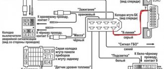
If everything is in order with the fastening of the ground wire, then you will have to check the instrument panel itself. To do this, you need to pull it out as far as possible from its mounting location without disconnecting the wires going to the pads. You will need to check on the white block X1 the ground wire going to contact 1, and at the same time check the voltage on contacts 6, 9, 10, it should be equal to 12 volts. Look, on the back side of the instrument panel, for the integrity of the paths along which electric current flows to the corresponding consumers.
Another cause of instrument panel failure may be the cigarette lighter. The fact is that through this socket, some drivers connect additional devices, such as: a cell phone battery charger, an electric tire pump, or a car interior vacuum cleaner. Considering that these consumers require high current, either the cigarette lighter itself fails or fuse F19 blows, which leads to failure of the instrument panel. By the way, you can also disable the cigarette lighter by holding it in the on position for a long time. In these cases, you can make the instrument panel work by disconnecting the cigarette lighter connector if fuse F19 is intact.
In principle, the driver himself can eliminate all malfunctions associated with a complete failure of the instrument panel. For this, he does not need any additional knowledge in electrical engineering. The only thing he needs to know is the probable causes of failure of the instrument panel.
Source
Arrangement
So, what can you see on the instrument panel in this car? The combination consists of several components:
- antifreeze temperature indicator in Celsius;
- tachometer - number of revolutions of the power unit;
- right and left turn indicators;
- speedometer - vehicle speed;
- fuel reserve - the volume of fuel in the tank;
- image of a gas station - a signal about the need to refuel;
- control indicator for starting dimensions;
- brake fluid level indicator;
- starting high beam headlights;
- knob for adjusting the clock;
- display with total and daily mileage;
- alarm control indicator;
- clock screen;
- battery charge level;
- check engine - indicates an engine malfunction;
- indicator indicating the handbrake is engaged;
- oil pressure level;
- choke light - only available on carburetor engines.
Repair (resurrection) BSK
Over the entire 4 years of using the car, the display unit (BI) turned on at most 10 times, and then everything was limited to the beeping and blinking of the lights at the moment when I took out the ignition key. Then I somehow noticed that if I moved the key in the lock, the BI would also blink. I started by studying this topic on the Internet.
I found two reasons for this problem: - poor contact on the BI connector, - worn out ignition switch. I think it’s unlikely that anyone will change the lock just to see errors on the BI; on the contrary, some people specifically disable it. But it would be convenient for me to see if there is fluid in the washer reservoir without opening the hood.
I climbed to look at the wires on the BI, it turned out to be original, manufactured on 06.2001. It is easier to remove it with the watch removed; you need to pull it hard. Indeed, the block with the wires was inserted crookedly. I corrected it and... lo and behold, it works. After a couple of days, I realized that the BI still turns on every other time, I have to turn the ignition on and off several times.
Of course, I wasn’t going to change the lock and suddenly I came across the same problem on one of the VAZ forums and it was solved with a guaranteed and simple solution. You just need to solder a diode between two wires No. 1 and No. 5 in the BI. Any diode is suitable, I had several from an old computer power supply, of course IN5406, which can withstand up to 600V would be superfluous here, but it just fit the length of the legs, so I installed it, a new diode with uncut legs will naturally also reach.
Fuse blown
As already mentioned, a malfunction of this panel element often leads to failure of the entire panel. You can find fuse F6 in the mounting block. If it does burn out, it is very important to identify the cause of the breakdown.
Otherwise, the new part will repeat the fate of the previous part and will burn out in the same way. Often the cause of the breakdown lies in a banal electrical circuit short circuit. Once the initial problem has been identified and corrected, you simply need to replace the fuse with a new part.
By the way, often the malfunction of this part becomes the reason that the dashboard and turn signals on the VAZ-2110 do not work. So, if you encounter such a problem, you can safely change the fuse.
On-board computer
Hi all!
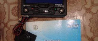
We have this BC and it seems to work, it shows something, but when switching modes absolutely nothing happens... Here is information on it, found by the way from one of the Drivers:
Cruise computer CC911
Trip computer for cars of the VAZ 2110 family with BOSCH controllers М1.5.4, М1.5.4N (JANUARY 5.1)
The CC911 trip computer (computer) connects to the vehicle’s electronic control unit (ECU) and allows you to:
Operational monitoring of parameters when parked and while driving (on-board voltage, fuel consumption, coolant temperature, driving speed). Prompt vehicle diagnostics using fault codes. Removing fault codes from the ECU memory. ATTENTION! The trip computer is not a measuring device, but only displays information located in the vehicle's ECU. Therefore, the accuracy of the displayed parameters is determined solely by the vehicle’s ECU, together with which the trip computer works.
Control is done with one button.
The built-in buzzer confirms pressing the control button and signals that the controlled parameters exceed the permissible limit.
When the side lights are turned on, the brightness of the indicator automatically decreases.
The computer turns on automatically when the ignition is turned on and goes into the data display state of the last selected mode (after the power supply to the vehicle's on-board network is interrupted, when the computer is turned on, the F1 mode data display is set).
When the ignition is turned off, the indicator goes off and the computer enters power saving mode.
If the computer does not turn on, check:
presence of supply voltage connection to the data line (including the presence of a jumper between the 9th and 18th pins of the immobilizer connector, if it is not included in the vehicle package). If there is no connection to the data line, then when the supply voltage is connected, the indicator will display the mode number F1 and after 5 seconds. the computer will turn off.
Operating mode selection
To change the mode, briefly press the control button. The computer enters the mode number indication state. In this case, the number of the current mode will be displayed on the indicator and the buzzer will beep in accordance with the number of the current mode. Each subsequent press of the button (with intervals between presses of no more than 2 seconds) increases the mode number by one, displayed on the indicator and confirmed by a single sound signal (when switching to mode F6, a long sound signal is heard). 2 seconds after the last press of the button, the buzzer will beep the number of the selected mode and the computer will return to the data display state.
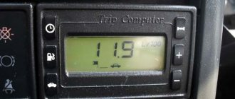
F1 - fuel consumption in liters from the moment the engine starts. F2 — vehicle speed in km/h. F3 - on-board network voltage in volts with a warning sound signal when the permissible values are exceeded. F4 - coolant temperature in the OS with a warning sound signal when the permissible value is exceeded. F5 - instantaneous fuel consumption in l/100 km when driving or in l/hour when parked. F6 - fault codes (sequentially in creeping mode). Holding the button for a long time (4 seconds) in F6 mode leads to the erasing of ECU fault codes (the CHECK ENGINE symbol on the dashboard goes out).
ATTENTION! It is not recommended to erase fault codes yourself to avoid losing information necessary when repairing the car.
Measuring fuel consumption per trip
To measure fuel consumption for a trip, while in the F1 mode data display state, long press the control button (hold for 2 seconds until the buzzer beeps for a long time) to reset the indicator readings. Stopping the engine does not reset the indicator readings and the next time the engine is started, the fuel consumption count will continue.
Sound alarm for exceeding the set speed
To turn on the audible alarm about exceeding the set speed, you should, while in the F2 mode data display state, accelerate the car to the required speed and long press the control button (hold for 2 seconds until the buzzer beeps for a long time) to record the indicator readings. The dots on the indicator begin to blink. Now, when the fixed speed value is exceeded, a pulsating buzzer signal will sound.
The audible alarm about exceeding the set speed can also be turned off in the F2 mode data display state by long pressing the control button. Shutdown confirmation - a long buzzer signal and the dots on the indicator go out. When the ignition is turned off, the sound alarm turns off automatically.
Alarm when monitored parameters exceed the permissible limit. This function only works when the engine is running.
When the coolant temperature rises above 110? C or the on-board network voltage goes beyond the limits of 11.7 ... 14.8 V, the computer goes into the emergency mode data display mode and the buzzer gives a series of warning sounds when the parameter is outside the tolerance (3 signals in a series when there is a deviation voltage and 4 signals in a series when there is a temperature deviation). By long pressing the control button, the alarm about violation of this parameter is turned off until the next time the ignition is turned on.
Tire pressure monitoring system
Recently, in a number of countries, at the state level, there has been a ban on the sale of cars without a tire pressure monitoring system. In our country, unfortunately, there is no such ban. However, we advise you to equip your car with such technology, which, believe me, has saved many lives around the world. The fact is that the tire pressure monitoring system warns the driver of danger in case of loss of pressure in the wheel, which allows you to react in time to an emergency situation on the road and stop the car in a timely manner. So, do not regret 3,000-5,000 rubles and purchase modern and very useful technology for your car that allows you to monitor the condition of your tires while driving. Read more…
Broken ground contacts
This problem manifests itself on the panel by displaying incorrect information; the tachometer needle may drop below the current level. The needles of other instruments may also freeze , either permanently or for a short period of time. The panel backlight may also disappear, but the arrows will show the correct data.
Bolt for fixing ground wires from all devices
Through trial and error, it was found that these glitches can occur due to the fact that the ground contact is broken . Under the dashboard, near the driver’s right foot (near the gas pedal), there is a special mount to which ground wires from all instruments are fixed.
To solve such a malfunction in the operation of the VDO dashboard, you simply need to improve the contact . Unscrew the bolt at “8”, disconnect and clean all contacts suitable for it. To be safe, it is advisable to treat them with “electronic contact cleaner”. After this, all that remains is to connect the wires and screw the bolt back.
Causes
The VAZ-2110 dashboard does not work - what to do in this case? First of all, it is necessary to understand the situation in detail and identify the original causes of the problem.
Of course, the most impressive malfunction of the panel is its complete failure. In such a situation, the instruments themselves, the indicators, and control lights stop working, and the arrows simply fall down. To solve this problem, the first thing you should do is check the functionality of the fifteen-amp fuse, which is designated “F6”. Often this is the reason why the dashboard on the VAZ-2110 does not work.
In general, there are several most common problems inherent in the shields of this car model. Each breakdown has its own characteristics and methods of correction.
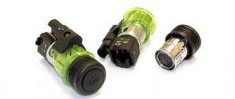
Checking the steering column switch
Checking the contacts in the steering column switch housing
In those cases, switching between the BC readings on the panel should be done with a switch on the steering wheel, but this cannot be done - you should make sure that it is working. This steering column switch is used on the panels: “VDO” 1118-3801010, “Schetmash” 2170-3801010-01 and “Avtopribor” 1118-3801010-02. To check whether the steering column switch is working properly, it must be removed and disassembled.
Disassembling the switch consists only of removing the cover, which is held in place by a small metal latch in the form of a bracket. There are 4 contacts under the cover, which are connected to the Reset button and to the switches. There are yellow and black wires coming from the “Reset” button. There are green and red wires coming from the top switch button. All these contacts must be checked with a multimeter for resistance.
If it is, then everything is fine with the switch and you need to disassemble the dashboard to inspect the contacts and tracks. On VDO panels with one window produced in 2006-2007, there is a factory defect - poor contact of one of the resistors, which, during driving, cracks and interrupts the connection between the steering column switch and the panel board.
Diagnostics
It doesn’t matter at all whether the VAZ-2110 dashboard with an 8-valve injector or a 16-valve carburetor does not work; the first step is to diagnose the dashboard itself. After all, its serviceability does not depend in any way on the inside of the car. Correct diagnosis involves performing several simple manipulations:
- checking lamps and replacing faulty parts;
- checking the wiring using an indicator or multimeter;
- inspecting contacts and cleaning them from oxidation deposits;
- checking fuses;
- monitoring the performance of devices.
If the dashboard of a VAZ-2110 with a Euro installation does not work, you should check fuses F18, F19 and F1. In cases with gasoline units, you should also pay attention to parts with numbers: F6 and F10.
Troubleshooting VDO Instrument Panel Resistor
The problem described below appears only on VDO dashboards manufactured in 2006-2007 under article number 1118-3801010. It was installed from 2004 to 2011 on the Kalina, VAZ 2110, 2111, 2112, 2113 and 2114 models. We can recognize the manufacturer by its logo located under the inscription “km/h”:
Removed VDO instrument panel
This is due to a manufacturing error . On the dashboard board there are two resistors labeled “E6E”. One of these resistors was soldered crookedly . As a result of such defects, over time, cracks form in the solder due to which contact is lost and the on-board computer stops responding to the joystick of the steering column switch.
If the steering column switch is working properly, then this is definitely a problem in the “E6E” resistor!
What is needed to eliminate the VDO instrument disease
To complete the work you need:
To diagnose this problem, you need to disassemble the dashboard. To do this, the dashboard is removed from the car and disassembled. And then the problem area on the board is inspected and soldered.
Disassembling the VDO dashboard
To disassemble the VDO panel, you need to snap off the front transparent plastic part of the panel, which is held on by six clips along the contour. Afterwards, the four star bolts are unscrewed and then the back cover is removed. After this, you need to snap off the black casing that remains on the front of the instrument panel. It is also held in place by plastic clips. This will allow you to remove the top glass and bottom cover from the dashboard.
Instrument panel with glass and bottom cover removed
To disassemble completely, remove the arrows and then unclip the latches from the board.
You can use a table fork to remove the arrows on the instrument panel from their seats. Before shooting, it is important to remember their location! The fork must be inserted under the arrow and, by gently pressing and rocking, tear it out of its seat.
The location of metal clamps in the center of the board and plastic ones at the edges
Then we proceed directly to removing the board from the remaining part of the instrument panel. To do this, you need to snap off the four metal clips in the center, as well as the four plastic clips along the contour. In the photo, these fasteners are circled in black.
How to fix a glitch with switching on-board computer readings on the panel
On the board you can see two resistors “E6E”. One of them, the one the arrow points to (circled), is located crookedly. This is the reason for the failure to switch between on-board computer data readings.
Crooked resistor on VDO panel board
It is necessary to heat the solder with a soldering iron and move the resistor with tweezers, then thoroughly solder the resistor contacts to the tracks. The result should look like this:
Result of soldering resistor E6E
Then we assemble everything in the reverse order and check its functionality. If everything is done correctly, the on-board computer will begin to respond to the joystick of the steering column switch.
Source
Tuning
This is what often causes the dashboard to malfunction. Perhaps the new shield was not fixed correctly, which is why it actually does not work. Either when installing the wiring, not all cables were connected, or they were simply bent.
In such cases, only individual elements of the dashboard often stop functioning: for example, displays, battery, handbrake or oil pressure indicators, as well as the carburetor choke light. The instrument panel of the VAZ-2110 does not work after tuning - what to do in this case? The first thing to do is replace the wires.
Types of tachometers
Analog instruments use an induction magnetic coil, thanks to which the number of crankshaft revolutions is shown by an arrow moving along the scale. This device is installed as standard on most machines. It is almost the same size as the speedometer and is located next to it on the dashboard. This arrangement of the device is convenient for the driver, since it is always in front of the eyes and makes it possible not to be distracted from the situation on the road.
In digital devices, information is reflected on a liquid crystal or diode display. The number of revolutions is transmitted either by a magnetic sensor that records the passage of a specific point on the crankshaft near the measuring device. An electronic sensor – optocoupler – can be installed. It generates a beam of light and determines the rotation frequency by its reflection from nearby objects. The digital device is useful when tuning engines and operations with electronic ignition units.
Removing the old and installing a new panel
The process of replacing a Europanel does not require inviting highly qualified craftsmen.
Accompanied by preliminary preparation:
The steering wheel and the facing part of the column are removed;
Removing the old panel
- The shields located at the feet of people sitting in front are dismantled.
- The curved plug is removed from under the handbrake;
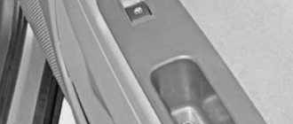
- The window regulator cover is removed and the cigarette lighter connector is removed.
- The cover is removed from the gearbox lever. The air ducts going to the rear seats are removed.
- The plastic covers of the roof pillars are removed. The radio is pulled out.
- The plugs are removed from the top of the panel. The nuts that appear are unscrewed.
- Then the bolts located along the contour of the lower edge, as well as at the feet of the driver and passenger, are unscrewed;
- The mounting block is dismantled and the plastic casing is removed.
Installation of a new panel sample
Both panels have different dimensions, therefore, installation is carried out using 3 methods:
- a new instrument cluster is adjusted to the existing panel dimensions;
- the panel is being completely replaced with a new sample;
- Installation of the Euro-plate is underway.
The latter method is rarely used. This is due to the fact that installation requires combining the wiring. Work is being carried out on a panel removed from the car.
If the panel on a VAZ 2110 does not work, you need to check the condition of each indicator. Make sure the safety elements are reliable. Next move on to checking the sensors. If a breakdown is detected, repair it. If the unit cannot be repaired, replace it.
Mechanics
The following diagram shows exactly how the speed sensor is designed.
Speed sensor for VAZ-2112
- 2110-3843010-13 – sensor;
- 2110-3843010-18 – sensor;
- 2108-3802820-10 – speedometer drive;
- 2101-3802718 – gasket;
- 2108-3802822 – drive housing;
- 2108-3802830 – sealing ring;
- 2108-3802834-20 – driven gear;
- 2108-3802833-20 – drive gear;
- 2101-3802717 – washer;
- 15896211 – M6 nut;
- 12601271 – wavy washer;
- 11500121 – pin M6x14.
Elements 1 and 2 are interchangeable.
Dismantling
To remove the sensor from the car, you need to disconnect its connector. The sensor housing is fixed near the CV joint - the desired point is shown by an arrow.
First step in dismantling
When the connector is disconnected, take a flat key “22” and unscrew the plastic nut. Then you can change the sensor or repair it.
What you need here is a flat key
To replace the sensor drive, use a “10” key to unscrew the M6 nut and remove it together with the washer. The drive housing is rocked from side to side - you need a 14mm spanner.
Installation requirements: on the one hand, it is necessary to obtain a tight seal, on the other hand, the plastic must not be broken.
Instrument panel test on video (speedometer self-diagnosis)
There are some things we don't specifically consider.
Power to the circuit shown in the previous chapter comes from main relay 6. It is also called the “ignition relay”. There is also fuse 1 in the circuit.
Additional relay and fuse box
When the ignition circuit is broken, both the speedometer and the ECU module do not work on the VAZ-2112, and the engine does not start at all. So advice about checking the relay would seem stupid.
Advice for those who have an oscilloscope
If you still decide to dismantle the sensor, connect a 1 kOhm resistor to its output (to the middle terminal). The resistor tap is connected to the “plus” of the power supply. By turning the shaft by hand, pulses can be observed at terminal 2. There are six pulses per revolution.
Car differences
A feature of the Priora steering is a large amount of play in the steering wheel, which takes some getting used to. At high speed, you have to “catch the car on the road,” as it were. Therefore, many drivers at the time gave preference to the VAZ 2110, which behaves more confidently at speed. But still, when cornering and when driving in a zigzag manner, the VAZ 21104’s movement is more comfortable and confident than that of its predecessor. The Priora behaves more dynamically at speed if an appropriate brace is installed between the supports of the front struts. In this case, drivers note improved handling.
The engines of both cars are reliable and simple. The Priora's engine has superior technical characteristics, but the eight and sixteen valve units do not differ much in the traction properties of both cars. Some will say one or the other is better, but in general we can say that they are all the same.
There is a little less transmission noise in the Prior and the cabin is probably a little quieter. But most likely this is due to the fact that the developers did a good job on sound insulation in the VAZ-21104.
And yet, driving in a Prior is quieter and more comfortable. The size of the car interiors is absolutely the same. The seats and all the plastics fit from one car to another. True, the seats on the Prior are a little higher. This fact will please small drivers and disappoint giants.
Priora at one time enjoyed enormous success in the post-Soviet space. In the Caucasian republics it was the best-selling car. In general, it is impossible to say with certainty which car is better and which is worse. Each person makes his own choice based on personal experience.
Some recommendations
- The search for the cause of the speedometer's inoperability should begin with an external inspection of the DS and the wires going to it. Wires often break in close proximity to the plug.
- If the speed sensor is covered with a layer of dirt or oily, you need to remove it, wipe it, reinstall it and check the speedometer readings again. Perhaps after this the instrument needle will again begin to show speed normally.
- If you cannot figure out the problem yourself, you should contact an electrician at a car service center.
Bottom part
Let's look at the indicators at the bottom of the control panel. If they don’t light up, it means the machine is working normally, and when any of them lights up, this indicates a malfunction in certain components. Most often, this is a signal that repairs are needed, and the sooner the better. From left to right:
- The indicator on the far left at the bottom is the air damper light (if you have a carburetor engine);
- Icon in the form of an oil can. If this light comes on, it means there is insufficient oil pressure in the engine. An alarming signal. You need to stop, find the reason;
- A round icon with the letter P inside on the control panel indicates that you have the parking brake on, which, as you know, should be turned off when moving away;
- Indicator of a fault related to the generator or battery (a symbolic image of the battery is shown on the indicator). Perhaps the battery is not charging from the generator, there is an open circuit, or the generator belt is loose or broken. In any case, your intervention and repairs are needed, otherwise troubles cannot be avoided;
- If the engine is running and the Check Engine indicator is on on the control panel, this is the most unpleasant thing for the driver, since it indicates serious malfunctions in the engine. In general, when this indicator lights up, it is recommended to stop driving and turn off the engine. Most likely it needs repairs;
- Typically there is a red triangle above the Check Engine. It lights up when the “hazard light” is on - an emergency signal sign;
- The headlight light indicates that the high beam is on. Designed to control headlights: when an oncoming car appears, do not forget to switch to low beam;
- A very important indication icon on the front panel (in a red circle) is a signal that there is not enough brake fluid. Perhaps it is leaking somewhere, which it is advisable to find out as soon as possible and, if necessary, carry out urgent repairs and replenish the level;
- The icon of a burning light is a control for turning on the dimensions;
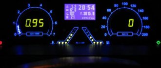
- In addition to the indicated lights, the front control panel has time indicators (and a button for setting hours and minutes) as well as a display that shows the total and daily mileage. On the new panel, this display may be narrow.