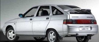
Many experienced car owners, when purchasing a new Kalina 2, immediately notice a significant drawback of this car - it does not have a coolant temperature indicator. Fortunately, solving this problem is quite simple using the on-board computer (BC). The most popular bookmaker for the new Kalina is State X1-G. This on-board computer was developed for the Granta, but due to the structural similarity of these cars, it is also suitable for the second generation Kalina. The manufacturer himself recommends this particular BC for Kalina 2, so no problems should arise.
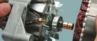
Lada-Kalina on-board computer
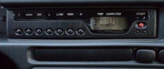
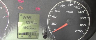
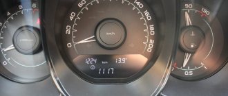
The LCD of the on-board computer is located on the dashboard and contains two lines:
- the top line displays the total/daily mileage counter;
- the bottom line displays: current time;
- outside air temperature;
- car driving time;
- average fuel consumption;
- instant fuel consumption;
- approximate remaining power reserve;
- average car speed;
- amount of fuel consumed.
To switch between display modes of the bottom line, use the keys on the steering column wiper switch: the keys located at the end of the switch switch functions “in a ring” forward and backward; The “Reset” key located at the bottom of the switch resets the values to “zero”.
The top line readings (total/daily mileage) are switched by a button located on the right side of the dashboard (under the fuel gauge). If the daily mileage counter is displayed, then to reset it, you must press and hold the button for 3 seconds.
The procedure for setting the clock on the Lada-Kalina:
- To switch from the current time indication mode to the setting mode, you must press and hold the “Reset” key for more than 3 seconds, while the hours and minutes will begin to flash;
- The minutes are set by pressing the “ring forward shift” key located at the end of the steering column wiper switch;
- The clock is set by pressing the “ring back shift” key located at the end of the steering column wiper switch;
- When you press the key once, the minutes/hours value increases by “1”; to change the values faster, you need to press and hold the key;
- When setting the minutes, the seconds counter is reset to zero (setting the hour counter does not affect the seconds counter);
- To return from the installation mode to the indication mode, you must briefly press the “Reset” key or, in the clock setting mode, do not press any key for 1 minute.
Detailed information about the displayed functions (their ranges) of the Lada-Kalina on-board computer:
- current time
(hour, min) - 0:00-23:59 (resolution 1 minute); - outside air temperature
(°C) — -40°C..+70°C; (resolution 1°C); - vehicle driving time
(hour, min), defined as the time during which the engine has been running since the last reset - 0:00-99:59 (resolution 1 minute; to reset, you must hold the “Reset” key for 3 seconds) - average fuel consumption
(l/100km) - 0.0-19.9 (resolution 0.1l/100km; after zeroing, the first 500 meters of the distance traveled are not indicated); - instantaneous fuel consumption
(l/100km) - 0.0-19.9 (not displayed if the speed is less than 1 km/h); - approximate remaining power reserve
(km) - 999-30 (resolution 5 km); - average car speed
(km/h) - 0-250 (resolution 1 km/h; after zeroing, the first 500 meters are not displayed); - amount of fuel consumed
(l) - 0-9999 (resolution 1 l; to reset, you must hold the “Reset” key for 3 seconds).
Top of page
Diagnostic parameters and auto diagnostic videos
For M74 Controller 11183–1411020-51/52, 11183–1411020-01/02.
| Parameter | Decoding | units change | Idling | 3000 rpm |
| TANS | Air temperature | °C | 15° – 45° | 15° – 45° |
| TMOT | Cooling temperature liquids | °C | 90° – 101° | 90° – 101° |
| UBSQ | Onboard voltage | IN | 13.0 – 14.5 | 13.0 – 14.5 |
| WPED | Pedal position | % | 11 – 15 | |
| WDKBA | Throttle position | % | 2 – 5 | 7 – 11 |
| NSOL | Desired speed | RPM | 840 | 3000 |
| NMOT | Engine speed | RPM | 840 ±40 | 3000 ±100 |
| MI | Air flow | Kg/h | 7 – 12 | 27 – 35 |
| ZWOUT | UOZ | Grd. P.K.V | 9 ±5 | 32 – 35 |
| RL_W | Load | % | 16 – 26 | 12 – 17 |
| FHO | Barocorrection factor | 0.8 – 1.02 | 0.8 – 1.02 | |
| TIEFF | Injection time | msec | 3.0 – 5.0 | 2.8 – 3.5 |
| DMVAD | Adaptation of XX adjustment | % | ±5 | – |
| USVKL | Signal from DC1 | IN | 0.01 – 0.89 | 0.01 – 0.89 |
| USHKL | Signal from DC2 | IN | 0.01 – 0.89 | 0.01 – 0.89 |
| FR_W | Lambda correction factor | 1.00 ±0.02 | 1.00 ±0.02 | |
| FRA_W | Lambda adaptation factor | 1.00 ±0.15 | 1.00 ±0.15 | |
| TATEOUT | Purge the adsorber | % | 0 – 8.2 | 0 – 18 |
| MSLEAK | Coeff. adaptation of fuel at XX | kg | ±2.5 | – |
| MSNDKO | Leaks at XX | kg/h | 2 – 8 | – |
| DTPPSVKMF | Period of the 1st DC | sec | < 1.8 | < 1.8 |
| FZABGZYL 1–4 | Misfires | |||
| FZKATS | Misfire influencing workers neutralizer | |||
| DMLLRI | Tech. correction XX | % | ±8 | |
| DMLLR | Tech. correction XX | % | ±8 | |
| AHKAT | Neutralizer aging factor | < 0.45 | < 0.45 | |
| B_LL | Bit XX | Yes | No | |
| B_LR | Closed Loop Adjustment Bit | Yes | Yes | |
| B_LRA | Resolution bit fuel adaptation | Not really | Not really | |
| B_SBBVK | DK ready bit 1 | Yes | Yes | |
| B_SBBHK | DK 2 ready bit | Not really | Not really | |
| B_TE | Canister purge bit | No Yes | No Yes | |
| B_KUPPL | Clutch pedal sensor bit | No Yes | No Yes | |
| B_BREMS | Brake Pedal Sensor Bit | No Yes | No Yes | |
| DFES | Fault codes | |||
| Rail fuel pressure | kPa | 380 ±20 | 380 ±20 |
https://www.youtube.com/watch?v=z3A5CPPC0DA
* All parameters are given for positive ambient temperature. Parameter values are advisory in nature.
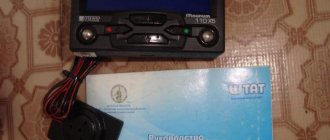
Installation of on-board computer “Prestige V1118”
The computer is manufactured in Nizhny Novgorod, the price at the end of 2009 was 2,200 rubles. Judging by the description, it outperforms the well-known State X5 computer in terms of functionality. The Prestige computer comes with gorgeous, detailed instructions (it’s in my nightstand at home), and there’s a pdf of it on the website (I printed it out and take it in the car). There is also a connection diagram for Kalina on the website (surprisingly, the instructions for the “Prestige V1118” computer do not contain information about connecting to this very 1118.)
- We remove the instrument cluster: tilt the steering column all the way down (required). We unscrew two
self-tapping screws.
We take out the instrument cluster and unfasten the connector. Examine the instrument cluster - you will find an Easter egg! The designer of the instrument cluster turns out to have provided three
attachment points (why - see)!
- Remove the plug for the diagnostic connector (on the tunnel, in front of the gearshift knob). We drag the computer harness under the panels from the connector into the instrument cluster compartment.
- Using the attached (downloaded) computer connection diagram, we find the necessary wires, cut them, and strip the ends. We strip the wire from the computer at a length 2 times greater - it will splice the cut standard wire. We splice one of the ends with the wire from the computer (as in the photo), solder it and put on heat shrink, then solder it to the other end of the standard wire, stretch the heat shrink and crimp it.
- We dock the connector to the instrument cluster, start the engine and check its performance in all modes (you never know.). If everything is fine, then we put it back.
- We connect the remaining wires to the diagnostic connector.
- We adjust the computer case to the place (we had to.) I filed the width and something else (in the photo - the recesses on the right left in the lower part of the case)
We install the computer in place and check the operation under current. Setting up the computer itself is straightforward; everything is written in its instructions.Basically - 2 hours of work. The computer program uses three methods for calibrating the fuel level sensor: according to statistics, after several trips with a full tank, a virtual tank and precise calibration.
Next - on lovers of truth and fans.
- I like the last technique, especially since I did this at work, more than once, and not with a car (I’ll boast, it’s possible here.)
- We buy gasoline in the amount of 50 liters in cans.
- Need 2-3 people. We park the car on a flat and deserted area, just in case - more fire extinguishers (although if something happens, it won’t help) and one free person (fire extinguishers for him, a notebook and pencil for him too, let him write the numbers).
- We get to the pump, turn off the supply line (be careful, gasoline is under pressure even with the engine turned off - wrap the fitting with a rag, and send smokers as far away as possible!).
- We put a hose of sufficient length onto the supply line, and lower the other end into a bucket.
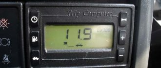
Mk-1 | llc state
Purchased MK-1 set Remove MK-1 from the package Screw the backing to the bracket
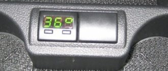
Remove the seal to the left of the instrument panel. Find the OBD-II diagnostic block of the car, it is located on the left, below, near the hood opening lever. Place the cable in the gap between the seal and the car pillar, leaving the required length of the cable for connection to the OBD II block. Remove the protective film from the MK-1 mount. The recommended location of MK-1 is shown in the photo. Hide the cable in the gap between the pillar and the car panel. Put the seal in place. Connect the diagnostic connector MK-1 to the OBD II diagnostic block of the car. After connecting to the diagnostic connector MK-1, data on the engine temperature will appear on the MK-1 indicator, after pressing the car speed again, etc. For more details, see the Installation and Operation Guide
Display of fuel level Display of on-board network voltage Display of error codes in the car, in this case there are no errors, which is what this message informs about.
Instructions for installing on-board computers "State XD"
Before you begin installing the on-board computer on Kalina, be sure to familiarize yourself with the connection diagram.
- Disconnect the negative terminal from the battery
- Unscrew the four screws securing the ashtray and remove it
- We find the contact block for turning on the alarm and take it out. It is to this that the main connection of the on-board computer “State XD” will take place.
Connecting the contacts of the on-board computer “State XD”
How to connect a fuel level sensor to the on-board computer “State XD”
After the main connection of the BC, it is necessary to connect the fuel level sensor. We will need a pink wire, which must first be routed through the inside of the dashboard behind the instrument panel.
For convenience, the instrument panel must be removed
It is also necessary to remove the fuse mounting block, which is located on the console to the left of the driver's seat.
In the depths, behind the block, there is a large gray block. A pink wire approaches the block from the back, through which a signal is sent to the fuel level sensor on the instrument panel. You need to connect the pink BC wire to it.
Connecting the K-line of the BC "State XD" to the on-board network
After the above mentioned manipulations to connect your on-board computer on Kalina, there are two wires left: “gray” and “blue”.
The “gray” wire is used to connect the BC to the vehicle’s on-board network. It is through this channel that all the necessary information for the bookmaker comes.
"Blue" wire is required to connect the on-board computer to the LPG control unit (if installed)
Basic mistakes
The table below summarizes the main error codes for Kalina category “P” without taking into account the letter prefix.
| Number | Decoding |
| 0030, 0031, 0032 | The heating of the lambda probe installed upstream of the converter is faulty (burnout of the spiral or short circuit) |
| 0036, 0037, 0038 | The heating of the lambda probe installed after the converter is faulty (burnout of the spiral or short circuit) |
| 0101 | Operating parameters of the engine air supply sensor are outside the tolerance range |
| 0102 | The signal level from the engine air supply sensor drops below the permissible level |
| 0103 | Increase in signal level from the air supply sensor to the engine above the permissible level |
| 0112 | The signal level from the air temperature sensor at the engine inlet drops below the permissible level |
| 0113 | Increase in signal level from the air temperature sensor at the engine inlet above the permissible level |
| 0115 or 0116 | Incorrect data from the engine temperature sensor |
| 0117 | The signal level from the engine temperature sensor drops below the permissible level |
| 0118 | Increase in signal level from the engine temperature sensor above the permissible level |
| 0122 | The signal level from the throttle angle sensor drops below the permissible level |
| 0123 | Increase in signal level from the throttle angle sensor above the permissible level |
| 0130, 0131 and 0133, 0134 | Missing or low signal from the first lambda probe |
| 0132 | Crankshaft Position Sensor Error |
| 0135 | Incorrect operation of the heating system of the first lambda probe |
| 0136 | Short circuit of the second lambda probe |
| 0137, 0138 | Missing or low signal from the second lambda probe |
| 0140, 0141 | Incorrect operation of the second lambda probe heating system |
| 0171, 0172 | Excessively lean or rich mixture |
| 0201-0204 | Gap in the injector control wiring (from 1 to 4 cylinders) |
| 0217 | Engine temperature goes beyond the upper limit |
| 0230 | Broken fuel pump drive relay |
| 0261, 0262 | Breakdown to "minus" or "plus" of the wiring for controlling the injector of the first cylinder |
| 0264, 0265 | Likewise for the second cylinder |
| 0267, 0268 | Same for the third cylinder |
| 0270, 0271 | Same for the fourth cylinder |
| 0300 | Numerous misfires on all cylinders |
| 0301-0304 | Problems with ignition in a specific cylinder (from 1 to 4 cylinders) |
| 0326-0328 | Failure of the knock sensor |
| 0335-0338 | Damage to the signal circuit from the crankshaft sensor |
| 0340 | Camshaft position sensor does not work (only for 16 valves) |
| 0342, 0343 and 0346 | Phase sensor (only for 16 valves) |
| 0351-0354 | Coil failure (16 valves only) |
| 0363 | Restriction of fuel supply due to ignition misfires |
| 0422 | Low efficiency of the neutralizer |
| 0441, 0444 and 0445 | Absorber malfunctions |
| 0480, 0481 | Radiator fans do not work |
| 0500 | Speed sensor faulty |
| 0506, 0507 | Failure of the idle control system |
| 0511 | No signal from IAC |
| 0560, 0562 and 0563 | Problems with voltage in the on-board network |
| 0601 | ECM memory error |
| 0615-0617 | Problems with the starter relay |
| 0627-0629 | You need to check the fuel pump relay |
| 0645-0647 | Problems with power supply through the relay to the compressor clutch |
| 0650 | Malfunction warning lamp does not work |
| 0654 | Failure of the tachometer circuit |
| 0685-0687 | Closing the main relay circuits |
| 0691, 0692 | Fan relay shorted |
| 1102, 1115 | Drop in resistance of the lambda probe heating coil |
| 1123, 1124 | Violation of mixture parameters at idle |
| 1127, 1128 | The same, but at medium load |
| 1135 | Short circuit of the first lambda probe heater circuit |
| 1136, 1137 | Violation of mixture parameters at low load |
| 1171, 1172 | Incorrect operating parameters of the CO sensor |
| 1335, 1336 | Throttle Position Error |
| 1386 | Errors in the data transmission circuit from the knock sensor |
| 1410, 1425 and 1426 | Absorber purge failure |
| 1500, 1501 and 1502 | Open or short circuit in the fuel pump relay circuit |
| 1509, 1513 and 1514 | Damage to the idle speed control circuit |
| 1606, 1616 | Rough Road Sensor Errors |
| 1620-1622 | Errors in ECU memory blocks |
| 2070, 2071 | Malfunction of the valve for changing the length of the intake channels |
| 2100, 2101 | Open circuit of the electric throttle valve |
| 2102, 2103 | Electric throttle actuator short circuit |
| 2122, 2123, 2127 and 2128 | Damage to the gas pedal position sensor |
| 2187, 2188 | Violation of the mixture composition at idle |
| 2135, 2138 | Asynchronous operation of throttle position sensors |
| 2176, 2178 | It is necessary to set the throttle valve to zero position |
| 2187, 2188 | Violation of the mixture composition at idle |
| 2301, 2304, 2307 and 2310 | Closing the control circuits of the ignition coils |
| 2500, 2501 | Exit of the operating parameters of the generator excitation circuit beyond the tolerance range |
| 0720 | Automatic transmission output shaft sensor faulty |
| 0717 | Failure of the automatic transmission turbine speed sensor |
| 0706, 0705 | Contacts in the automatic transmission selector are faulty |
| 0962, 0963 | Failure of the pressure regulation solenoid in the automatic transmission |
| 0973, 0974 | Failure of the gear shift solenoid in the automatic transmission |
| 0731-0734 | Transmission errors in automatic transmission |
| 0744, 1744 | Automatic transmission clutch malfunctions |
| 0711-0713 | Failure of the automatic transmission oil temperature sensor |
| 0863 | Automatic transmission unit communication error via CAN bus |
| 1735-1738 | Gear selection lock |
| 062F | Resetting the memory of the automatic transmission control unit |
| 230 | No signal from fuel pump relay |
| 263, 266, 269 and 272 | Failure of the control unit (driver) of the injector nozzles |
| 650 | Burnout of the check indicator or its wiring |
New Lada: LADA 4×4 Urban 3 doors. – Operating manual – Official LADA website