Types of on-board computers
There are quite a few types of on-board computers VAZ-2110. The price of all devices is different - from 1,200 rubles to 20,000. It all depends on the type and manufacturer. For example, devices that are installed in standard places are low cost and are not very convenient to use. But there are on-board computers that are installed instead of the standard dashboard. Large selection of instruments, various color schemes, display layout, etc.
Such devices include on-board computers VAZ-2110 “Gamma”, “Multitronics”. But they also cost a lot - over 10,000 rubles. Installing such a device in a service center will cost another half the cost. But you can do all the work yourself if you know how to read diagrams and understand them. But the main thing is that for ease of use it is necessary to calibrate the sensors.
Troubleshooting VDO Instrument Panel Resistor
The problem described below appears only on VDO dashboards manufactured in 2006-2007 under article number 1118-3801010. It was installed from 2004 to 2011 on the Kalina, VAZ 2110, 2111, 2112, 2113 and 2114 models. We can recognize the manufacturer by its logo located under the inscription “km/h”:
Removed VDO instrument panel
This is due to a manufacturing error . On the dashboard board there are two resistors labeled “E6E”. One of these resistors was soldered crookedly . As a result of such defects, over time, cracks form in the solder due to which contact is lost and the on-board computer stops responding to the joystick of the steering column switch.
If the steering column switch is working properly, then this is definitely a problem in the “E6E” resistor!
What is needed to eliminate the VDO instrument disease
To complete the work you need:
To diagnose this problem, you need to disassemble the dashboard. To do this, the dashboard is removed from the car and disassembled. And then the problem area on the board is inspected and soldered.
Disassembling the VDO dashboard
To disassemble the VDO panel, you need to snap off the front transparent plastic part of the panel, which is held on by six clips along the contour. Afterwards, the four star bolts are unscrewed and then the back cover is removed. After this, you need to snap off the black casing that remains on the front of the instrument panel. It is also held in place by plastic clips. This will allow you to remove the top glass and bottom cover from the dashboard.
Instrument panel with glass and bottom cover removed
To disassemble completely, remove the arrows and then unclip the latches from the board.
You can use a table fork to remove the arrows on the instrument panel from their seats. Before shooting, it is important to remember their location! The fork must be inserted under the arrow and, by gently pressing and rocking, tear it out of its seat.
The location of metal clamps in the center of the board and plastic ones at the edges
Then we proceed directly to removing the board from the remaining part of the instrument panel. To do this, you need to snap off the four metal clips in the center, as well as the four plastic clips along the contour. In the photo, these fasteners are circled in black.
How to fix a glitch with switching on-board computer readings on the panel
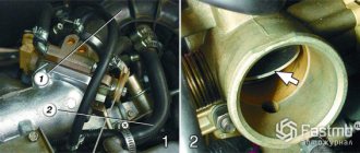
On the board you can see two resistors “E6E”. One of them, the one the arrow points to (circled), is located crookedly. This is the reason for the failure to switch between on-board computer data readings.
Crooked resistor on VDO panel board
It is necessary to heat the solder with a soldering iron and move the resistor with tweezers, then thoroughly solder the resistor contacts to the tracks. The result should look like this:
Result of soldering resistor E6E
Then we assemble everything in the reverse order and check its functionality. If everything is done correctly, the on-board computer will begin to respond to the joystick of the steering column switch.
Source
On-board computer options
On-board computer STATE X1M-station wagon.
Regular BC.
BK-40.
BK-10.
The main differences between a BC injector and a carburetor
The main differences between the bk, depending on the type of power supply, are the on-board capabilities for the VAZ 2110. The carburetor type is the simplest. The main reason is that carburetors are largely controlled mechanically, and electronics play a secondary role. Therefore, its standard set of functions is extremely small. You can find out about:
- time of day or set an alarm;
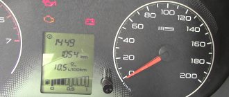
- current and average fuel consumption, as well as power reserve;
- average speed and driving mode;
- engine or outside air temperature;
- diagnostic information that allows you to find out about an engine operation error and decode it.
Setting an alarm
- Press button 4 in Alarm mode.
- Use buttons 5, 6 to set the desired hour value.
- Press button 4. Use buttons 5, 6 to set the desired minute value.
- Press button 4 to complete the alarm setting.
- In the “Current time” mode, the alarm symbol will light up (the alarm is on).
* If the counter of any of the accumulated parameters (“Travel time”, “Travel time with stops”, “Total consumption”, “Trip mileage”) overflows, all accumulated ones, as well as calculated ones (“Average fuel consumption”, “Forecast”) are reset mileage on remaining fuel", "Average speed") parameters, with the appearance of a two-tone sound signal.
Turning off the alarm
- Press button 4 in Alarm mode.
- Press button 1 to turn off the alarm. “—.—” will appear in the digital digits, and in the “Current time” mode the alarm symbol will not light up (the alarm is turned off).
Advantages of injection engines
The engine designs are the same, only the following systems differ significantly:
- Fuel mixture injection.
- Ignition.
- Engine control.
The main advantages of injection engines:
- If faults occur, diagnostic tools will provide an accurate diagnosis in a matter of minutes. In rare cases, it becomes necessary to take the car to a service center for servicing.
- Ideal operation at idle speed, provided that all sensors function stably. Starting the engine in winter is much easier.
- Fuel consumption (depending on the firmware, however) is significantly less than that of carburetor engines.
- Injection systems require virtually no intervention. Sensors and actuators rarely fail.
The cost of spare parts is significantly higher than for carburetor engines. But they also break less often. If the injector is new or has just been serviced, then with proper use it will last for more than one year without breakdowns. If the sensors break down, they can be replaced within a few minutes. And some devices can be repaired.
Benefits of using on-board computers
On VAZ-2110 cars, the on-board computer (instructions are included with the device) has several functions:
- Visual notification of current and average fuel consumption.
- Accurate tachometer and voltmeter.
- There is a function that allows you to remind about a scheduled oil change.
On-board computers can notify the driver of the following faults:
- A lamp lights up, indicating engine failure. If the motor operates normally and there are no symptoms of breakdowns, then most likely the power circuit of the lamp itself is faulty.
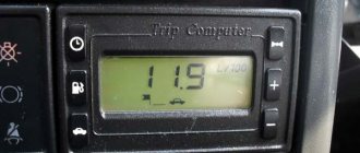
- Excessive gasoline consumption. In some cases the value exceeds 12 l/100 km. A complete diagnosis of the injection system and flashing of the electronic control unit controller will help.
Pros of bookmaker
Installing a computer on a VAZ 2110 will open up a lot of good options and has a huge number of advantages:
- the presence of a trip computer allows you to find out about the power reserve;
- the ability to combine a computer and a navigator;
- option for heating the spark plugs of a disabled vehicle;
- the ability to check errors and eliminate them immediately. Replacing the bearing that caused the malfunction significantly
- cheaper than subsequent extensive repairs.
We recommend: How can you care for the interior of your car?
ADJUSTING THE COMPUTER FUNCTION
Clock correction
Press button 4 in the “Current time” mode. At the sixth signal of the exact time, press button 1, this resets the seconds and rounds the clock readings.
Setting the current time (calendar)
Disadvantages of injection systems
Among the negative qualities are the following:
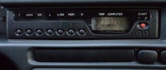
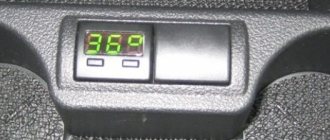
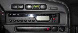
- The on-board computer “State” of the VAZ-2110 provides complete information, but it is inconvenient to perceive it. The display is located to the side, under the tape panel. Therefore, in order to consider any data, you will need to stop.
- A very expensive catalyst, located literally 10 cm from the road surface, is easily damaged. Repairing it is not always possible, and the cost is very high. In the event of a breakdown, not only fuel consumption will increase, but also the level of CO in the exhaust.
- Initially, only carburetors were installed on the “ten” engines. Later, the engines were sharpened for the installation of injection systems. Consequently, dismantling some sensors and devices turns out to be problematic due to their inconvenient location.
Purpose and types
On-board vehicles not only see a car malfunction, but are also a diagnostic scanner that carries out the conclusions received from the sensors and, due to their capabilities, speeds up the diagnosis of the problem or its repair.
There are 2 types of purpose of on-board computers:
- Universal. These devices determine geographic coordinates, connect to the Internet, receive and send various data, and are also a multimedia system with the ability to view video and listen to audio.
- Narrowly targeted. The presented class contains route, diagnostic computers and an electronic vehicle control system.
Operation of injection cars
It is imperative to comply with the requirements that will facilitate the operation of the car. In order for the on-board computer “State” of the VAZ-2110 to produce errors as little as possible, and to increase comfort, be sure to adhere to the following recommendations:
- Carry out soundproofing - this will get rid of unnecessary noise. For example, the fuel pump is quite loud. And it can be inconvenient.
- Be sure to treat all body elements with anti-corrosion compounds.
- The vehicle should only be refueled with recommended brands of fuel. If you fill with low-octane gasoline, the engine will not work properly.
- Timely maintenance will solve any problems regarding the operation of the motor.
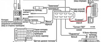
Electrical connections
During the preparation stage, you must perform the following steps:
- Disconnect the negative terminal from the battery.
- The VAZ-2110 on-board computer is connected to the alarm block. Find it and position it as conveniently as possible.
- You will need to first locate the orange wire (at pin seven).
- Connect the red-white wire to it, which is located in the computer connection harness.
- To the red-black wire installed in the tenth pin, connect the red one from the harness coming from the trip computer.
- And connect the red on the block with the red-black coming from the BC harness.
- Find the black wire on the fifth pin. And you connect the same one from BC to it.
- A white wire is installed on the eighth contact, which you connect to a similar one going to the BC.
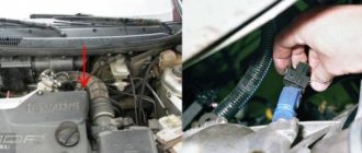
Broken ground contacts
This problem manifests itself on the panel by displaying incorrect information; the tachometer needle may drop below the current level. The needles of other instruments may also freeze , either permanently or for a short period of time. The panel backlight may also disappear, but the arrows will show the correct data.
Bolt for fixing ground wires from all devices
Through trial and error, it was found that these glitches can occur due to the fact that the ground contact is broken . Under the dashboard, near the driver’s right foot (near the gas pedal), there is a special mount to which ground wires from all instruments are fixed.
To solve such a malfunction in the operation of the VDO dashboard, you simply need to improve the contact . Unscrew the bolt at “8”, disconnect and clean all contacts suitable for it. To be safe, it is advisable to treat them with “electronic contact cleaner”. After this, all that remains is to connect the wires and screw the bolt back.
What does the on-board computer notify?
- When the car is moving, a light comes on, indicating a malfunction of the power unit. It is possible that there really are problems with the engine. It's easy to notice by the sound. If the light is on, but the engine behaves normally, do not rush to go to a car service center. A common problem with the BC on the VAZ 2110 is a small short circuit. Carry out diagnostics - cheaply and effectively.
- Fuel consumption is too high, it has even exceeded the maximum limit of 12 liters. If such a problem is detected, it can only be solved by flashing the controller firmware. Doing this on your own is difficult and sometimes impossible. Trust exclusively highly qualified specialists.
Checking the steering column switch
Checking the contacts in the steering column switch housing
In those cases, switching between the BC readings on the panel should be done with a switch on the steering wheel, but this cannot be done - you should make sure that it is working. This steering column switch is used on the panels: “VDO” 1118-3801010, “Schetmash” 2170-3801010-01 and “Avtopribor” 1118-3801010-02. To check whether the steering column switch is working properly, it must be removed and disassembled.
Disassembling the switch consists only of removing the cover, which is held in place by a small metal latch in the form of a bracket. There are 4 contacts under the cover, which are connected to the Reset button and to the switches. There are yellow and black wires coming from the “Reset” button. There are green and red wires coming from the top switch button. All these contacts must be checked with a multimeter for resistance.
If it is, then everything is fine with the switch and you need to disassemble the dashboard to inspect the contacts and tracks. On VDO panels with one window produced in 2006-2007, there is a factory defect - poor contact of one of the resistors, which, during driving, cracks and interrupts the connection between the steering column switch and the panel board.
Rules for driving a car with an injector
A car equipped with an injector is less susceptible to ambient temperatures. However, in severe frost, the injection Lada also experiences difficulty starting. Here it is worth using the on-board computer with the function of heating spark plugs. Every time the temperature drops below a certain value and the car is turned off, a special heating of the tips is carried out to ensure a stable engine start.
Also, the VAZ engine sometimes overheats, which can cause valve burnout and costly overhauls. However, this is possible if the cooling system is faulty. If necessary, you can activate the Tropic function for the on-board computer of the VAZ 2110. When the temperature reaches more than the value set by the owner, the forced cooling fan turns on.
User manual
Additionally, it is worth setting up the computer for the VAZ 2110 after all devices have been installed. The device, as a rule, has a special cross. These buttons help you configure the device. For example, to connect a fuel level sensor, you need to drain the tank, turn on the device, and press the diagnostic button.
The device will carry out the analysis, and then a numerical designation will appear on the display. This amount of gasoline should be poured. The computer will then move on to another phase of analysis. Once completed, you can fill the tank full. The full set of settings is indicated in the operating manual for a specific device and you can make a choice in favor of the desired functions.
Installing an on-board computer on a VAZ 2110 with detailed instructions
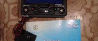
Each standard on-board computer on the VAZ 2110 is accompanied by instructions , according to which you can dismantle the old computer and put a new one in its place. Therefore, first of all, arm yourself with this guide.
It’s not difficult to figure out for yourself how to connect an on-board computer to a domestically produced VAZ 2110 car . It is necessary to act consistently and follow stages.
- First, remove the terminal that comes from the battery.
- Find the alarm block and remove it. The on-board computer is connected to it.
- The orange wire should be removed from the seventh contact.
- In its place, a red and white wiring is attached, which is pulled from the on-board computer harness.
- Disconnect the orange wire and install it in the connector from which you previously removed the wire.
- The red wire with black stripes will be disconnected from the tenth contact. The red wire from the BC harness is attached here. Instead of red, connect red-black. Essentially, you are swapping wires.
- Disconnect the black wire from the fifth contact. A wire of the same black color from the on-board computer harness is connected to it. This is a very important point, don't miss it.
- The black wire from the block is connected here.
- Now it’s the turn of the eighth contact. The white wire is removed from it, and the white wire from the harness is connected in its place. That is, a change of places occurs again.
- Make sure there is contact between the wires.
- Check the quality of fixation of each disconnected and connected wiring. Use insulating tape in areas where they are curled.
- The harness is pulled through the internal section of the console to the site for subsequent installation of the on-board computer.
- Next, you should carefully and firmly connect it to the sensor, which is responsible for adjusting the fuel level in the car.
- Remove the instrument panel to give yourself access to the gray block.
- Disconnect the fuse box. It is located to the left of the driver.
- From the gray block, remove the pink wire that transmits the signal to the fuel level sensor. The pink wire from the harness of your on-board computer is connected to it.
- Install the sideboard in its rightful place.
- Reconnect the battery terminal to turn the ignition on. Start the engine and check if everything works on the installed on-board computer.
We recommend: Is it worth buying an electric scooter?
By following fairly simple instructions, you should be able to connect the VAZ 2110 BK to your car without any problems. Carefully study each point, think about whether you can really do everything yourself.
As we have already noted, the approximate cost of a new on-board computer intended for installation on a VAZ 2110 car is 2 thousand rubles. There is no need to purchase additional tools or materials for self-installation, that is, the whole process will cost you 2 thousand.
When you contact a service station, you will be asked for about 2 thousand rubles more to connect the on-board computer. This is the best case scenario.
Considering the relative simplicity of the work, there is no need to trust it to car mechanics. By consistently performing each step and following the instructions, you will be able to equip your VAZ 2110 with an on-board computer with your own hands.
Repair (resurrection) BSK
Over the entire 4 years of using the car, the display unit (BI) turned on at most 10 times, and then everything was limited to the beeping and blinking of the lights at the moment when I took out the ignition key. Then I somehow noticed that if I moved the key in the lock, the BI would also blink. I started by studying this topic on the Internet.
I found two reasons for this problem: - poor contact on the BI connector, - worn out ignition switch. I think it’s unlikely that anyone will change the lock just to see errors on the BI; on the contrary, some people specifically disable it. But it would be convenient for me to see if there is fluid in the washer reservoir without opening the hood.
I climbed to look at the wires on the BI, it turned out to be original, manufactured on 06.2001. It is easier to remove it with the watch removed; you need to pull it hard. Indeed, the block with the wires was inserted crookedly. I corrected it and... lo and behold, it works. After a couple of days, I realized that the BI still turns on every other time, I have to turn the ignition on and off several times.
Of course, I wasn’t going to change the lock and suddenly I came across the same problem on one of the VAZ forums and it was solved with a guaranteed and simple solution. You just need to solder a diode between two wires No. 1 and No. 5 in the BI. Any diode is suitable, I had several from an old computer power supply, of course IN5406, which can withstand up to 600V would be superfluous here, but it just fit the length of the legs, so I installed it, a new diode with uncut legs will naturally also reach.
Connection diagram
The process of diagnosing an ECU using a special scanner.
Electronic control units of the VAZ-2110 are the main tool for controlling and automating most processes in the car. To adjust the software, they often resort to replacing the “brains” with more “flexible” ones and reflashing the ECU.
First of all, it is necessary to clarify several terms that will be required when considering questions about changing the electronic control unit:
- Wiring compatibility . To replace it, the connectors on the old ECU and the new one will need to match.
- Software is a predetermined algorithm that can change depending on the needs or desires of the motorist.
- The hardware component is the electronic control unit itself, boards or other components that allow the systems associated with the ECU to function normally.
For the VAZ-2110 family there were two types of connectors. So, for the “brains” January 5.1.x, Bosch M1.5.4, Bosch MP7.0, and VS 5.1 there was a 51-pin connector, but for January 7.2(+), Bosch M7.9.7(+) and M73 - 81 -pin.
That is, the interchangeability of control units is caused by the pinout of the unit.
ECU January 7.2.
Differences
Fundamental differences between 81-pin blocks and blocks of previous generations:
- Overall body dimensions and weight have been reduced.
- New, more modern connectors with improved connection reliability.
- The controllers have built-in switches, therefore, instead of ignition modules, ignition coils can be used, which increase the reliability of the ECM as a whole.
- There is no software or hardware compatibility with any of the previously released units.
Even electronic control units from the same manufacturer will differ significantly in pinout. Therefore, the interchangeability of the “brains” will depend on the number of connector pins. Also, it is worth understanding that the firmware will play a big role. When changing the ECU, the motorist will have to reflash the unit for the correct operation of all vehicle devices.
ECU January 5.1.
A very important nuance remains that the software of the control unit must be compatible and comply with the type of injection, as well as the toxic standards laid down by the manufacturer.
Assignment of contacts of ECU Bosch M1.5.4, MP7.0 and January-5.1
Pinout of 55-pin ECU.
Let's look at the pinout of control units with 55-pin “brains”:
| Bosch M1.5.4 (1411020 and 1411020-70) January 5.1.1 (71) | Bosch M1.5.4 (40/60) January-5.1 (41/61) January 5.1.2 (71) | Bosch MP7.0 | |
| 1 | Ignition 1-4 cylinders. | Ignition 1-4 cylinders. | Ignition 1-4 cylinders. |
| 2 | . | Ground ignition wire. | . |
| 3 | Fuel pump relay | Fuel pump relay | Fuel pump relay |
| 4 | Stepper motor PXX(A) | Stepper motor PXX(A) | Stepper motor PXX(A) |
| 5 | Canister purge valve. | Canister purge valve. | |
| 6 | Cooling fan relay | Cooling fan relay | Left fan relay (only on Nivas) |
| 7 | Air flow sensor input signal | Air flow sensor input signal | Air flow sensor input signal |
| 8 | . | Phase sensor input signal | Phase sensor input signal |
| 9 | Speed sensor | Speed sensor | Speed sensor |
| 10 | . | General. Oxygen sensor weight | Oxygen sensor weight |
| 11 | Knock sensor | Knock sensor | Knock sensor input 1 |
| 12 | Power supply for sensors. +5 | Power supply for sensors. +5 | Power supply for sensors. +5 |
| 13 | L-line | L-line | L-line |
| 14 | Weight of injectors | Weight of injectors | Weight of injectors. Power "ground" |
| 15 | Control of injectors 1-4 | Oxygen sensor heater | Check Engine Light |
| 16 | . | Injector 2 | Injector 3 |
| 17 | . | Recirculation valve | Injector 1 |
| 18 | Power supply +12V non-switchable | Power supply +12V non-switchable | Power supply +12V non-switchable |
| 19 | Common wire. Weight of electronics | Common wire. Weight of electronics | Common wire. Weight of electronics |
| 20 | Ignition 2-3 cylinders | Ignition 2-3 cylinders | |
| 21 | Stepper motor PXX© | Stepper motor PXX© | Ignition 2-3 cylinders |
| 22 | Check Engine Light | Check Engine Light | Stepper motor PXX(B) |
| 23 | . | Injector 1 | Air conditioner relay |
| 24 | Stepper motor weight | Weight of stepper motor output stages | Power grounding |
| 25 | Air conditioner relay | Air conditioner relay | . |
| 26 | Stepper motor PXX(B) | Stepper motor PXX(B) | Weight of sensors TPS, DTOZH, DMR |
| 27 | Ignition switch terminal 15 | Ignition switch terminal 15 | Ignition switch terminal 15 |
| 28 | . | Oxygen sensor input | Oxygen sensor input |
| 29 | Stepper motor PXX(D) | Stepper motor PXX(D) | Oxygen sensor 2 input signal |
| 30 | Weight of sensors MAF, DTOZH, DPS, DD, DPKV | Weight of sensors MAF, DTOZH, DPS, DD, DPKV | Knock sensor input 2 |
| 31 | . | Reserve output high current | Rough road sensor input signal |
| 32 | . | . | Fuel consumption signal |
| 33 | Control of injectors 2-3 | Oxygen sensor heater. | . |
| 34 | . | Injector 4 | Injector 4 |
| 35 | . | Injector 3 | Injector 2 |
| 36 | . | Exit. Intake pipe length control valve. | Main relay |
| 37 | Nutrition. +12V after the main relay | Nutrition. +12V after the main relay | Nutrition. +12V after the main relay |
| 38 | . | Low-current backup output | . |
| 39 | . | . | Stepper motor РХХ © |
| 40 | . | Reserve input discrete high | . |
| 41 | Request to turn on the air conditioner | Request to turn on the air conditioner | Oxygen sensor heater 2 |
| 42 | . | Reserve input discrete low | . |
| 43 | Signal to tachometer | Signal to tachometer | Signal to tachometer |
| 44 | CO - potentiometer | Air temperature sensor | . |
| 45 | Coolant temperature sensor | Coolant temperature sensor | Coolant temperature sensor |
| 46 | Main relay | Main relay | Cooling fan relay |
| 47 | Programming permission | Programming permission | Air conditioner request signal input |
| 48 | Crankshaft position sensor. Low level | Crankshaft position sensor. Low level | Crankshaft position sensor. Low level |
| 49 | Crankshaft position sensor.High level | Crankshaft position sensor.High level | Crankshaft position sensor.High level |
| 50 | . | Recirculation valve position sensor | Programming permission |
| 51 | . | Request to turn on the power steering | DC heater |
| 52 | . | Reserve input discrete low | . |
| 53 | Throttle position sensor | Throttle position sensor | Throttle position sensor |
| 54 | Fuel consumption signal | Fuel consumption signal | Stepper motor IAC (D) |
| 55 | K-line | K-line | K-line |
We recommend: Arranging the exterior of your car
Description of contacts ECU M7.9.7 / January 7.2
Let's look at the pinout of control units with 81-pin “brains”:
| № | Compound |
| 1 | 21114 - Not used / 21124 - Ignition coil 2 cylinders. |
| 2 | 21114 - Ignition 2-3. Control of the primary winding of the ignition coil, act. level is low. / 21124 — Ignition coil 3 cylinders. |
| 3 | Ignition circuit weight |
| 4 | 21114 - Not used / 21124 - Ignition coil 4 cylinders. |
| 5 | 21114 - Ignition 1-4. Control of the primary winding of the ignition coil, act. level is low. / 21124 - Ignition coil of cylinder 1. |
| 6 | Injector 2. Active level low |
| 7 | Injector 3. Active level low |
| 8 | Output to tachometer. |
| 9 | Not used |
| 10 | Fuel consumption signal |
| 11 | Not used |
| 12 | Battery, terminal 30 of the ignition switch. |
| 13 | Nutrition. Ignition switch terminal 15 |
| 14 | Main relay |
| 15 | Contact "A" DPKV |
| 16 | TPDZ |
| 17 | TPS mass / TPS mass, DND |
| 18 | Input - oxygen sensor |
| 19 | Input - knock sensor |
| 20 | Knock sensor weight |
| 21 | Not used |
| 22 | Not used |
| 23 | Not used |
| 24 | Not used |
| 25 | Bosch Only - High Current Output, Reserved |
| 26 | Bosch Only - High Current Output, Reserved |
| 27 | Injector 1. Active level low |
| 28 | Not used / DK2 heater control output |
| 29 | Not used / Engine cooling fan control output 2 |
| 30 | Not used |
| 31 | CE lamp, act. level low |
| 32 | Power supply TPDZ / Power supply TPDZ, DND |
| 33 | Power supply for mass air flow sensor |
| 34 | DPKV input, contact “B” |
| 35 | Weight of DTOZH / Weight of DTOZH, mass air flow sensor, 1 DC (UDK), 2 DC (DDK) |
| 36 | Mass of the mass air flow sensor |
| 37 | Signal input from mass air flow sensor |
| 38 | Not used |
| 39 | Signal input from DTOZH |
| 40 | Signal input from intake air temperature sensor |
| 41 | Not used |
| 42 | Not used / DND signal input |
| 43 | Not used |
| 44 | On-board voltage input at the main relay output |
| 45 | Phase sensor power output |
| 46 | Canister purge valve control output |
| 47 | Injector 4. Active level low |
| 48 | Oxygen sensor heater control output |
| 49 | Not used |
| 50 | Additional starter relay control output |
| 51 | Controller weight |
| 52 | Not used |
| 53 | Controller weight |
| 54 | Not used |
| 55 | Not used / Signal input DK2 (DDK) |
| 56 | Not used |
| 57 | Input for encoding calibration data options. The controller memory can contain 2 sets of calibration data; switching is performed by shorting to ground. |
| 58 | Not used |
| 59 | Speed sensor |
| 60 | Not used |
| 61 | Weight of output stages |
| 62 | Not used |
| 63 | On-board voltage input at the main relay output |
| 64 | Output “D” IAC |
| 65 | Output “C” IAC |
| 66 | Output “B” IAC |
| 67 | Output “A” IAC |
| 68 | Engine cooling fan relay control output, act. level - low |
| 69 | Air conditioner relay control output, act. level - low |
| 70 | Fuel pump relay control output, act. level - low |
| 71 | K-Line |
| 72 | Not used |
| 73 | Not used |
| 74 | Not used |
| 75 | Input request to turn on the air conditioner, act. level - high |
| 76 | Power steering request input, act. level - high |
| 77 | Not used |
| 78 | Not used |
| 79 | Phase sensor signal input |
| 80 | Weight of output stages |
| 81 | Not used |
Choice of "Brains"
AvtoVAZ Lada 2110 cars have been equipped with several electronic control units throughout their production history. Thus, the following ECUs can be found on vehicles:
- January 4 - the cost of such an electronic control unit is 4,000 rubles.
- Bosch M1.5.4 - the average price will be 5,500 rubles.
- January 5.1 - the market price will be about 6,000 rubles.
- VS 5.1 - cost 5,000 rubles.
- Bosch MP7.0 - the cost of the control unit will be around 6,000 rubles.
- Bosch M7.9.7 is a little more expensive than its brother, the price ranges from 6000-6500 rubles.
- January 7.2 and January 7.2+ - these blocks will cost the car owner 5000-5500 rubles.
According to the experience of motorists and the recommendations of specialists, it is best to take electronic control units marked Bosch MP7.0, January 7.2+ and January 5.1.
If you have to change the remaining blocks, it is recommended to take an ECU with these markings, since they are more “flexible” for changing the software.
Comparison table of the presented models
In order to compare the presented products, we suggest taking a look at the table with their characteristics.
| Model | Mounting location | Dimensions (mm) | Display resolution (pix) | Processor size | Price, rub) |
| Multitronics CL-550 | 1 din | 190x60x45 | 320x240 | 32 | from 5199 to 5300 |
| Multitronics RI-500V | 1 DIN | 19x7x16 cm | 128x32 | 16 | from 6199 to 6800 |
| Multitronics C340 | 1 DIN | 19x7x16 cm | 320x240 | 32 | from 4210 to 4890 |
| Gamma GF 271 | 1 DIN | 37x47x40 | 132x48 | 32 | from 5100 to 7000 |
| Gamma GF 212T | 1 DIN | 237x47x40 | 128x32 | 32 | from 3800 to 4200 |
On-board computer diagnostics
Faulty sensors can be determined using ECU diagnostics.
To identify faults in the electronic control units of the VAZ-2110, diagnostic equipment is used. Usually they use a tablet or laptop with special software. Also, the motorist, if the operation is performed independently, will need a special OBD II cable.
The process of diagnosing an ECU using a laptop.
Diagnostics are carried out to determine errors in the electronic control unit and troubleshoot problems in on-board systems, especially on engines. After identifying the error, it is necessary to decipher and find the cause of the malfunction in order to eliminate it.
conclusions
Determining the compatibility of the electronic engine control unit is quite simple; to do this, you should look at the pinout of the connectors, and also read the technical specifications. You can replace the “brains” yourself.
Sources
- https://MasteraVaza.ru/salon/bortovoj-kompyuter/kolodka-bortovogo-kompyutera-vaz-2110-583
- https://FB.ru/article/342090/bortovyie-kompyuteryi-na-vaz—podklyuchenie-bortovogo-kompyutera-vaz—instruktsiya
- https://carfrance.ru/zamena-bortovoj-kompyuter-vaz-2110/
- https://DaciaClubmd.ru/repair/elektrika/bortovoj-kompyuter-vaz-2110
- https://luxvaz.ru/vaz-2110/17-podklyuchnie-bortovogo-kompyutera.html