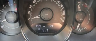
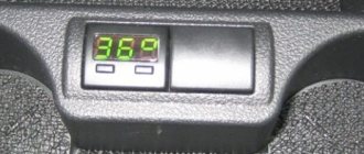
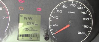
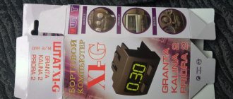
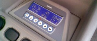
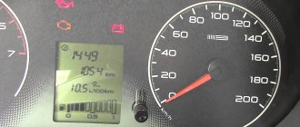
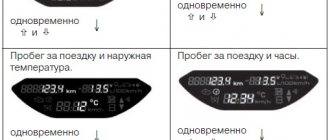
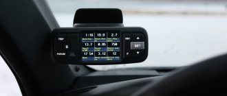
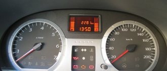
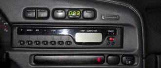
The “simplest” on-board computer for the Lada Granta is the BC STATE X1-G. It is compatible with ITELMA M74, M75 units, as well as BOSCH ME17.9.7. The connection is made to the OBD connector, which is located in the cabin. No additional power is required. We will look at how to install it, as well as how to update the firmware. Sometimes you need to update it immediately to get compatibility with a new car. Therefore, read the review carefully.
All functions of BC STATE in one video.
Instructions and files
| File | Pages | Format | Size | Action |
| 16 | 1.54MB | To read the instructions, select the file in the list that you want to download, click on the “Download” button and you will be redirected to a page where you will need to enter the code from the image. If the answer is correct, a button to receive the file will appear in place of the picture. If there is a “View” button in the file field, this means that you can view the instructions online, without having to download it to your computer. If you think the material is not complete or you need additional information on this device, for example a driver, additional files, such as firmware or firmware, then you can contact the moderators and members of our community, who will try to quickly respond to your question. |
Improved model
The State 115X23-M model, used on Samara-2 and Samara, is considered more advanced. What distinguishes it from its previous relative is its two-line display, which contains twice as much information.
The option to calculate cost and mileage has been added to the existing functions. There are also additional sections:
- "Dynamics".
- "Taxi".
- "Control XX".
- “Engine diagnostics” (monitors the operation of the injectors and the pump pumping gasoline).
- "Sleep mode"
- Reminder of the need to undergo maintenance or continue the MTPL policy.
Characteristic
BC takes up little space but does a lot of work. Below you will find out what kind of work this is and what additional capabilities it has.
Device for car
The lineup
The model range is not too extensive, but still varied:
- UniComp staff;
- State 110 and 115;
- State x1.
There are other models, each of which corresponds to the personal preferences of car enthusiasts.
Functional
- Ability to display and delete ECM errors.
- Displays operating parameters, or more precisely, coolant temperature, electrical voltage in the on-board network.
- Shows emergency parameters: high engine temperature, system problems.
There are also several additional functions:
- “Afterburner” - this function resets the controller memory to factory settings.
- “Plasmer” is a useful function that is responsible for warming up and drying the spark plugs before a cold start.
Of course, the bookmaker’s capabilities are not limited to this (the author of the video is Alexander Ignatiev).
Advantages and disadvantages
Regarding the pros and cons, only a few words can be said:
- Due to its extensive functionality, which a standard bookmaker installed as standard cannot boast of, the gadget is especially popular. Among other things, it can be purchased at an affordable price.
- In addition, it has additional settings, including the ability to diagnose the system using error codes, the list of which is covered in the instructions received upon purchase.
- If you go deeper and look for disadvantages, some car enthusiasts complain about the standard BC firmware, but this problem is easily solved: you just need to download the software from the site and reflash the device.
Additional functions
"Tropic" function.
Automatic fan control Allows you to change the cooling fan activation threshold. I set the response temperature to +98°C.
Function "Plasmer". Drying and warming up candles
In difficult weather conditions (humid weather, freezing temperatures), pre-drying and warming up the spark plugs several times increases the likelihood of a successful launch.
“FAST AND THE FURIOUS” function
Resetting the controller to its original factory settings. In this case, the dynamics and fuel consumption will be restored to normal values.
Indicator of not switched off lights or dimensions
When you turn off the ignition, there is a sound notification that the headlights or headlights are not turned off.
Speed Warning
It is possible to set up an audible warning about speeding. I don’t use this function because I always try to adhere to the speed limit.
Typical faults and solutions
As an example of malfunctions, you can take the on-board computer State 110, or rather State 110 x5.
This model is characterized by the following unpleasant “tricks”:
- If you're having problems with the power supply, you may need to take a look at the wiring harness and make sure all the pins are connected tightly.
- If you regularly hear an alarm sound while driving, this most likely indicates that the overheating alarm has turned on, the fuel level in the tank is low, or there is unwanted voltage in the on-board circuit.
- If a message appears on the display that there is no connection with the controller, make sure that the wiring to the K-line is correctly connected. The instructions contain a connection diagram and it is best to proceed based on it.
- Unstable thermometer readings indicate that the contacts are broken or the temperature sensor wire has broken.
Computer installed in the console
On-board computer STATE-UNIVERSAL X1 Installation and operation manual
Transcript
1 On-board computer STATE UNIVERSAL X1 Installation and operation manual 1. PURPOSE DESIGNED for installation on VAZ cars of the 2110 family instead of the button cover above the clock. CONNECTS into the standard connector for the MK and into the diagnostic block. Compatible with controllers January 5.1, January 7.2, Itelma VS 5.1, Bosch M1.5.4 (M), Bosch M Automatic adjustment of display brightness (decrease in brightness when the side lights are turned on). Non-volatile memory (saves all values when the cell is removed from the battery). Manual adjustment of the accuracy of fuel consumption and mileage readings within ±30%. Produced according to specifications Code OKP 005 (OKP): Certificate of Conformity ROSS.RU.AYU96.NO FUNCTIONS ROUTE COMPUTER 7 FUNCTIONS, including Fuel level in the tank and Mileage on remaining fuel. DIAGNOSTIC TESTER 7 FUNCTIONS, including reading diagnostic codes and clearing them. 3 PARAMETERS ALARM with the ability to separately block the sound signal PLAZMER - drying and warming up spark plugs to facilitate cold engine starts. TROPIC - automatic control of the cooling system fan when the engine temperature specified by the user is reached. Parking time meter 3. EQUIPMENT On-board computer STATE UNIVERSAL X1…1 Harness for connecting BC…1 Installation and operation manual…1 Packaging…1
2 4. INSTALLING BC Attention! Before installation, carefully study this manual. Consultations can be obtained by calling technical support. BEFORE STARTING WORK, DISCONNECT THE MASS TERMINAL FROM THE BATTERY! 4.1 Find the injection system diagnostic connector - it is located to the right of the steering column and looks as shown in the figure. The vehicle is equipped with one of these two connectors. Diagnostic connector OBD I Lay the gray wire of the harness (diagnostic line wire] BC from its installation location to this connector - to do this you will have to remove the left panel of the console. Connect this wire to socket "M" for the OBDI connector or "7" for the OBD II connector as shown in the figure. OBD II diagnostic connector When diagnosing a car at a service station, it must be disconnected. 4.2 Find the standard connector for the trip computer - it is located not far from the clock and looks as shown in the figure. Connect the BC harness to this connector. MK connector 4.3 Connect the BC connector — the computer will beep and display the version number (for example, U-5}. If the BC is installed in addition to the standard trip computer, use a harness to connect to the clock block (sold separately). If the BC does not respond to turning on the ignition, check that the connection is correct diagnostic line. Another reason for the lack of communication when the immobilizer is turned off may be the absence of a jumper in its connector. As a rule, it is installed during the first maintenance. If there is still no jumper, install it between pins 9 and 18 (a piece of paper clip is good for this). Install your bookmaker in its normal location. 4.4 Connect the MASS terminal to the battery.
3 5. ROUTE COMPUTER BC switches to trip computer mode when you press the left button (the first press displays the function designation, and a second press within a second switches functions in a ring). STARTING A RIDE: Holding the left button for more than two seconds (START) in any mode means the start of a trip and is confirmed by a long beep. At the same time, the trip counters are reset to zero: fuel consumption, mileage and travel time, as well as their derivatives: average speed, average consumption, forecast of mileage with remaining fuel. 5.1 Fuel level in the gas tank (calculated), liters Initially set by the driver and adjusted manually at each refueling. As fuel is consumed, the BC recalculates the fuel level in the tank. Correction: Hold the right button (CORRECT) for more than 2 seconds. By pressing the left (decrease by 1 l) or right (increase by 5 l) buttons, enter the volume of fuel poured. The maximum level is 45 liters. Holding any button in correction mode adds 43 liters to a full tank. Exit from the correction mode occurs automatically 5 seconds after the last press of any button. 5.2 Forecast of mileage with remaining fuel, kilometers Calculated by dividing the fuel level in the tank by the average consumption for the trip. It is considered uncertain (dashes are displayed on the display) with an uncertain fuel level in the tank (dashes in the previous mode) and with an uncertain average consumption (mileage less than 5 km). 5.3 Fuel consumption per trip, liters The counter of fuel consumed from the beginning of the trip is reset to zero by holding down the left button (START), along with the mileage counter and trip time. For values up to 100 liters, the accuracy of the liter indication is 1 liter for larger values. The accuracy of fuel calculation can be changed within ± 30% in the average consumption correction mode. 5.4 Mileage for the trip, kilometers The counter of the distance traveled from the beginning of the trip is reset by holding the left button (START) together with the fuel meter and trip time. For values up to 100 km, the indication accuracy is km, for values from 100 to 1000 km - 1 km, for larger values - 10 km. 5.5 Travel time, hours, minutes The ignition on time counter is reset by holding the left button (START) together with the fuel and mileage counter. Indication accuracy: for values less than 10 hours - 1 minute, for large ones - 10 minutes. 5.6 Average fuel consumption per trip, l/100 Calculated by dividing fuel consumption by mileage - per trip. When the mileage is less than 5 km, the average fuel consumption is considered uncertain (dashes on the screen). Correction: Hold the right button (CORRECT). Enter a correction when calculating fuel within ± 30%. The BC immediately recalculates all fuel-related values, with the exception of the fuel level in the tank. Exit from the correction mode occurs automatically 5 seconds after the last press of any button.
4 5.7 Average travel speed, km/h Calculated by dividing the mileage per trip by the travel time. If the travel time is less than 5 minutes, it is considered undefined (dashes on the screen). Correction: Hold the right button (CORRECT). Enter a correction when calculating mileage within ± 30%. The impact of the amendment begins from the moment it is introduced. Exit from the correction mode occurs automatically 5 seconds after the last press of any button. 6. DIAGNOSTIC TESTER BC switches to diagnostic tester mode when you press the right button (CORR.) (the first press displays the name of the function, and pressing it again within a second switches functions in a ring). 6.1 Diagnostic codes of the electronic engine control system You can find out the reason why the SNACK ENGINE lamp turns on on the dashboard of your car by switching to this mode. The display shows the code number and the code itself as a running line. The decoding of the codes can be found in the table at the end of the instructions. If there are no codes in the controller's memory, dashes are displayed on the screen. Correction: by holding the right button (CORR.), you can delete diagnostic codes from the memory of the injection system controller. Confirmation of deletion (positive response from the injection controller) is accompanied by a three-tone signal. If the cause of the code is not eliminated, it will appear again (sometimes this happens very quickly and it may seem that the bookmaker cannot remove the code). 6.2 Coolant temperature, degrees Celsius The BC constantly monitors this temperature. When the threshold of 110 C is exceeded, the BC automatically goes into alarm mode. Continued operation of the vehicle at this temperature may result in costly repairs. Correction: To enable or disable automatic cooling fan control, hold down the right button (CORRECT). The switching threshold can be changed from 90 C to 105 C. To disable control, set the threshold above 105 C (OFF will light up on the screen). Holding the right button (CORR.) quickly turns off the control, and holding the left button (START) turns it on and sets the threshold to 98 C. A burning dot indicates that the fan is controlled by the BC. Exit from the correction mode occurs automatically 5 seconds after the last press of any button. 6.3 Voltage in the on-board network, Volts When the engine is running, the voltage should be Volts (normal generator operation). A voltage of more than 15 Volts will lead to boiling of the electrolyte from the battery and failure of the lamps. When the voltage is less than 12.5 Volts, the battery does not recharge. The BC constantly monitors the voltage in the on-board network and automatically switches to alarm mode when the voltage goes beyond the Volt limit while the engine is running. 6.4 Tachometer, rpm (x1000) This mode will allow you to control the engine idle control process. If the idle air control (IAC) operates normally and there are no problems in the fuel and air supply systems, the speed should vary within no more than ± 20 rpm. 6.5 Throttle position, % This mode allows you to check the serviceability of the throttle position sensor
5 (TPDZ). To do this, turn on the ignition without starting the engine and gently press the accelerator pedal. The BC readings should change smoothly from 0 to 100. If the readings change abruptly, the sensor is faulty. If you press the pedal all the way down, adjust the pedal travel less. 6.6 Current fuel consumption, l/h or l/100 This mode allows you to change your driving style to achieve maximum efficiency. At a speed of less than 20 km/h, the readings are in l/h - the dot flashes, at a higher speed in l/100 - the dot is constantly on. 6.7 Speedometer, km/h More accurate than the standard speedometer in the instrument panel. Can be useful if the standard speedometer is faulty or disabled for some reason. Correction: To turn speed control mode on and off, hold down the right button (CORRECT). The alarm threshold can be changed from 20 km/h to 180 km/h. Holding the right button (CORRECT) in the correction mode quickly turns off the indicator (OFF lights up on the screen), and holding the left button (START) turns it on and sets the threshold to 70 km/h. Exit from the correction mode occurs automatically 5 seconds after the last press of any button. 7. ALARMS The transition to the alarm mode occurs automatically. You can turn off the sound of the alarm by pressing any button. The sound blocking is removed when the ignition is turned off. The alarms are blocked separately from each other. 7.1 Engine overheating Turns on when the engine temperature exceeds the threshold of 110 C. The current temperature is displayed on the screen. 7.2 Alarm in the on-board network It turns on when the voltage in the on-board network goes beyond the Volt limit while the engine is running. When the engine is not running, this indicator is disabled. 7.3 Speed control If speed control is turned on (in the speedometer correction mode) and the speed exceeds the set threshold, then the BC emits a short two-tone signal without changing the current operating mode. Re-activation occurs only if the speed has previously decreased below the threshold by 10 km/h. 8. ADDITIONAL SERVICE 8.1 Vehicle parking time meter, hours/minutes Viewing is possible only when the ignition is turned off by pressing any button. Automatically starts at speeds less than 15 km/h and resets at higher speeds. Starting or stopping the engine does not reset it. You can forcefully reset this counter by holding the left button (START) for more than 2 seconds (the reset is confirmed by a short double signal). When the side lights are on, this mode is constantly on. By pressing the right button (CORRECT) you can force the display to turn on for 1 hour. 8.2 Automatic fan control If the outside temperature is high or the quality of the coolant is low, it may boil. In the injection controller, the threshold for turning on the cooling system fan is
6, 101 C or even 105 C is selected. As practice shows, sometimes this value is unjustifiably overestimated. The BC can control the fan, and the switch-on threshold can be changed, and the switch-off threshold is always 4 C less. By default, this function is disabled and can be enabled from the Coolant Temperature mode. 8.3 Drying and warming up the spark plugs, seconds In difficult weather conditions (humid weather, freezing temperatures), pre-drying and warming up the spark plugs several times increases the likelihood of a successful start. The function is available only immediately after turning on the ignition and when the engine temperature is less than 40 C. When you press the left button (START), a timer starts for 120 seconds. While the timer is running, the candles dry and warm up. You can extend the drying period by pressing the left button (START) again, interrupt it by pressing the right button (CORRECT) or start the engine. After warming up and drying the spark plugs is completed, the BC will emit a sound signal and go into normal operation mode - the spark plugs are dried and warmed up, start the engine. 9. LIST OF DIAGNOSTIC CODES Error number Description 0102 Mass air flow sensor, low output 0103 Mass air flow sensor, high output 0112 Intake air temperature sensor, low output 0113 Intake air temperature sensor, high output 0115 Incorrect coolant temperature sensor signal 0116 Coolant temperature sensor, signal out of range 0117 Coolant temperature sensor, output low 0118 Coolant temperature sensor, output high 0122 Throttle position sensor, output low (sensor 1) 0123 Throttle position sensor, high output (sensor 1) 0130 Pre-catalyst oxygen sensor faulty 0131 Pre-catalyst oxygen sensor, low output 0132 Pre-catalyst oxygen sensor, high output 0134 Pre-catalyst oxygen sensor, open signal circuit 0135 Oxygen sensor before the converter, heater faulty 0136 Oxygen sensor after the converter, open signal circuit 0137 Oxygen sensor after the converter, low signal level 0138 Oxygen sensor after the converter, high signal level 0140 Oxygen sensor after the converter, open signal circuit 0141 Oxygen sensor after the converter, heater faulty 0171 Fuel supply system too lean 0172 Fuel supply system too rich 0200 Injector control circuit faulty 0201, 0202, 0203, 0204 Cylinder 1, 2, 3, 4 injector control circuit open 0261, 0264, 0267, 0270 Injector control circuit cylinder 1, 2, 3, 4 short to ground 0262, 0265, 0268, 0271 Injector control circuit of cylinder 1, 2, 3, 4 short to +12V 0300 Random or multiple misfires detected
7 Error number Description 0301, ,0304 Misfire detected in cylinder 1, 2, 3, Knock sensor breakage 0327 Knock sensor, low signal level 0328 Knock sensor, high signal level 0335 Crankshaft position sensor, no signal 0336 Crankshaft position sensor, no signal signal is outside the permissible limits 0340 Camshaft position sensor is faulty (Phase sensor error) 0342 Camshaft position sensor low signal level 0343 Camshaft position sensor high signal level 0422 Converter efficiency below threshold 0441 Incorrect air flow through valve 0444 Canister purge valve, open check circuit 0445 Canister purge valve circuit short to ground 0480 Fan 1 relay control circuit; open, open circuit check 0500 Vehicle speed sensor, no signal 0501 Vehicle speed sensor error 0503 Vehicle speed sensor, intermittent signal 0505 Idle speed control error 0506 Idle speed control locked, low speed 0507 Idle speed control locked, high speed 0560 On-board voltage below threshold system performance 0562 On-board voltage is low 0563 On-board voltage is high 0601 Controller permanent memory error, for M1.5.4 - no connection with immobilizer 0603 Control unit RAM malfunction 0604 Controller internal RAM checksum error 0607 Controller detonation channel signal is incorrect 0615 Control circuit starter relay, open 0616 Starter relay control circuit, short to ground 0617 Starter relay control circuit, short to +12V 1102 Low resistance of the oxygen sensor heater 1115 Faulty oxygen sensor heating control circuit 1135 Malfunction of the oxygen sensor heater circuit to the converter 1140 The measured load differs from the calculated load 113 ground 1514 Idle air control control circuit, open or short to +12V 1541 Fuel pump relay control circuit, open 1570 Immobilizer, no positive response or open circuit 1600 No communication with the immobilizer 1602 Loss of on-board network voltage
8 Error number Description 1603 Control unit EEPROM fault 1606 Rough road sensor, incorrect signal 1612 Processor reset error 1616 Rough road sensor, low signal 1617 Rough road sensor, high signal 1620 Control unit ROM fault 1621 Control unit RAM fault 1622 Unit EEPROM fault control 1640 Electrically reprogrammable memory, read-write test error 10. SERVICE CENTERS The STATE trademark is constantly expanding its network of service centers in Russia. If you do not have information about the service center in your city, you can contact the store where you purchased our products, or call the STATE corporate center by phone: (8482), or look on the website. Service center TM STATE is located at: , Samara region, Tolyatti, st. Belorusskaya 14e. The entrance diagram to the service center is located in point 11. Please send claims regarding product performance to the Bureau of Claims, Warranty or Post-Warranty Repair of BC and Software Updates located at: , Samara region, Togliatti, PO Box 2911 telephone: (8482) e-mail: Wholesale sales are carried out from a warehouse in Togliatti telephone: (8482), e-mail: shtat.rf Representative office in Moscow: http: telephone: 8 (495) Representative office in Samara: telephone: CERTIFICATE OF COMPLIANCE AND ACCEPTANCE On-board computer STATE UNIVERSAL X1 manager…. complies with the technical data given in this Manual, performs its functions, has been tested by the seller, and does not have a harmful effect on the environment and humans. Issued according to specification code OKP 005 (OKP): Certificate of Conformity ROSS.RU.AYU96.NO7012. date of issue... Signature of persons responsible for acceptance... Stamp of the Quality Control Department of the Russian Federation Samara region, Togliatti, PO Box 2911 Consumer complaints should be sent to: phone: (8482) Technical support phone number (v.1
Connection and configuration features
The on-board computer is connected based on the manual. It is important to disconnect the ground terminal from the battery before starting work.
The following manipulations are:
- Remove the console and unscrew the screws.
- Using clamps, connect the BC wires coming from the block with identical ones in color coming from the cigarette lighter. After all the contacts have been assembled, assemble the structure and connect the removed buttons, installing them in their places.
- Connect the 6-pin harness block and install the BC.
- After this, you can return the battery terminal to its place.
- The BC parameters are configured depending on the device and machine model.
Price issue
You can take a closer look at the price and decide for yourself whether it’s worth purchasing the device using photographs.
About energy consumption
The BC STATE model X1 G consumes 0.015 Amps when in standby mode. The rest of the time the current can reach 200 mA. In practice it is difficult to obtain a value exceeding 170-180 mA. For comparison:
- Good (expensive) signaling, standby mode - 10-15 mA;
- Conventional signaling with a key fob - 25 mA;
- Alarm in the “Disarmed” mode – 100-300 mA.
In general, our BC is quite “gluttonous”, but not as much as an alarm system.

