If the electrical signal is supplied in a distorted form, then the malfunction will be felt throughout the entire VAZ injector system. Unlike the carburetor circuit, where the pedal directly controls the damper, in injection engines the pedal is not connected to the actuator; IAC idle speed regulator. In the places where the housing is connected to the radiator, bitoplast should be glued. Adjustment must be carried out by selecting the positions of the braid. Connectors may become unusable, wiring may break, contacts may oxidize. how to connect a car signal If the foam has come loose, carefully glue it back, you can add strips of bitoplast. The information is intended for self-repair of cars.
One of the most important parameters, without which the car will not even start. Optional element, installed together with item.
An optional part, used mainly on export vehicles.
Limit switch for reverse gear lights.
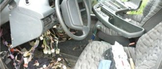
VAZ 2109 wiring repair
Signs of trouble
The electrical circuit of a VAZ with a high or low panel includes various elements that ensure the operation of both primary and additional functions of the machine.
If a VAZ 21099 injector or carburetor malfunctions, the vehicle may behave differently:
- The car engine does not start, the car cannot drive. If such a problem occurs on a VAZ 2109, then there can be many reasons, ranging from the failure of the generator or battery to the inoperability of the distributor.
- The car starts and drives, but the electrical equipment or part thereof does not work or does not work correctly. There can be many reasons, as in the previous case, ranging from the failure of a particular device to wear and tear of the wiring or fuse box.
Complete electrical circuit of the "nine"
If the engine does not start, but fuel is supplied to the carburetor or injector itself, most likely the malfunction is caused by the electrics:
- First you need to check if the battery is charged. If this is a VAZ 2109 carburetor, then you need to check the operation of the spark plugs, as well as the wires connected to them. In addition, the problem may also be a failure of the distributor. Malfunctions occur much less frequently in the operation of the engine compartment wiring.
- If you have a VAZ 21093 injector with a low or high panel, then there is a possibility that the cause of the malfunction is the operation of the ECM. When the control unit cannot process signals from the controllers and transmit the corresponding commands to the actuators, the reason should be sought in the operation of the system (video author - Sasha Radchenko).
What can be changed in the electrical circuit
Let's figure out what exactly car owners undergo alterations.
Moreover, we will indicate only those alterations that are not prohibited by the manufacturer and current regulations:
Wiring diagram for VAZ 2109i with a high panel
For reference: the visual differences between the standard panel and the “high” one are that the radio compartment is moved to the level of the dashboard. Accordingly, the wiring on the VAZ 2109 under the instrument panel must be replaced.
Interior modifications
Many owners come to mind with the desire to improve the lighting in the car interior.
Let us remind you that inside a passenger vehicle there are several places equipped with lighting sources:
Layout of incandescent lamps for a VAZ 2109 car
If you, as the owner, like a high panel in the cabin, then you cannot do without replacing the standard wiring. Because the:
Electrical wiring for a VAZ 2109 in the process of connecting to devices
Accordingly, without replacing the electrical wires it will not be possible to use:
Differences in the terminal blocks of the “low” and “high” instrument panel
As for making changes to the instrument panel lighting, today there are sets of special lamps on sale along with the wiring with which they are connected to the car’s electrical network.
Why do you think the owner needs a GAZelle wiring diagram?
Tuned instrument panel lighting for VAZ 2109
You can install such kits yourself; it is only important to adhere to accuracy and safety rules.
Advice: carry out all electrical wiring replacements and connecting instrumentation only with the battery disconnected.
Carburetor engine
The VAZ 2109 wiring diagram can work differently, depending on the type of engine, in particular, we are talking about starting the power unit:
- When the ignition is turned on, a charge is supplied to the battery terminals through the high-voltage wiring harness. In this case, the driver will be able to turn on music, lighting, and indicators will appear on the control panel.
- After this, the starter unit rotates the crankshaft and the entire piston group. As a result, the generator starts.
- Next, power begins to flow to the ignition coil, which, in turn, produces high-voltage voltage. This charge is transferred through the wires to the switchgear, while the device continues to function.
- The engine crankshaft then begins to rotate the distributor drive. The contacts close on the device, as a result of which the charge begins to flow to the spark plugs. The flammable mixture ignites, which leads to the engine starting (the author of the video is NIKOLAY GOROSHKO).
Classic ignition
If the wiring of a VAZ 21099 in a carburetor engine begins to act up and you think that it is because of it that the engine does not start, then the circuit is diagnosed as follows:
- First, you should check the circuit in the area from the coil to the generator unit. Please note that all contacts in this section should not have breaks or oxidation; if such a problem exists, then the wiring should be replaced or the contacts should be cleaned.
- After this, you need to check the short circuit itself; first, the presence of a spark is diagnosed. To understand whether there is a spark or not, you need to pull out the end of the high-voltage cable from the switchgear harness, after which this tip must be brought to the block head. When trying to start the engine, a spark may slip between the tip and the cylinder head. If it is missing, the coil is repaired or replaced.
- It would be a good idea to diagnose the switchgear and spark plugs. If the high-voltage cables are worn out or broken, most likely they will need to be replaced. In addition, you need to check the internal unit and the condition of the spark plugs - if there is carbon deposits on them, the engine may also not start.
Wiring diagram VAZ 2114 injector - a separate section of seat heating equipment
A specially dedicated section of on-board wiring responsible for powering, activating and adjusting seat heater devices. Here is a detailed description of all structural elements:
- 1 – driver’s seat heater;
- 2 – output to the terminal block of the dashboard;
- 3 – separate connector for the driver’s door, wire supply to the control button;
- 4 – heating element of the front passenger seat;
- 5/6 – adjustment key for the element specified in paragraphs No. 1 and 4;
- A1 – grounding wire, fastened with a bolt to the car body.
July 2009
| Mon | W | Wed | Thu | Fri | Sat | Sun |
| « Jun | Aug » | |||||
| 1 | 2 | 3 | 4 | 5 | ||
| 6 | 7 | 8 | 9 | 10 | 11 | 12 |
| 13 | 14 | 15 | 16 | 17 | 18 | 19 |
| 20 | 21 | 22 | 23 | 24 | 25 | 26 |
| 27 | 28 | 29 | 30 | 31 | ||
Today I returned from a friend. Initially he had a carburetor, then he decided to make an overhaul + tune the car a little. At my suggestion, he decided to build an injector. Fortunately, all the spare parts necessary for this turned up. parts. Today I told him how to connect it all. Well, naturally, he didn’t understand much, so I decided to write a fairly detailed guide about connecting. In fact, a lot of people have been asking about this lately. Hope this will be useful.
There are different modifications of injectors, with and without an oxygen sensor, with and without an absorber, phased, pair-parallel and simultaneous injection. There are also different mounting blocks. For example, I took COURT January 5.1 (Bosch 1.5.4), i.e. without absorber and DC. On the electrical equipment side there is a high panel with a mounting block 2112-3722010-60.
First, the entire COURT diagram
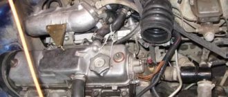
Now let's see what needs to be changed in the engine compartment.
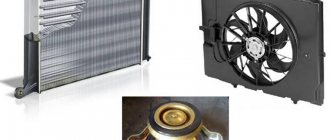
Let's start with the fan. This braid has a single contact; if you open the insulation a little, you can see that it comes with a black and white wire.
This is the contact for connecting the fan.
The fan worked differently on different units, but the main feature was that it was turned on by a sensor on the radiator. Now it will be turned on by the injector unit. And instead of the old scheme
It will be switched on according to a new scheme from the “brains” i.e. you just need to take and attach one contact to the body, and connect the second to the black and white wire from the braid. All with a fan!
Now about other contacts... Here's the overall picture
I will not consider all the sensor plugs, but will consider only those points that confuse a novice electrician. Two brown wires have appeared in the engine compartment. These are the “cons”, which are called G1 and G2 in the EMS diagram. They need to be screwed onto the body. Usually they are screwed onto the cylinder head in the area of the thermostat.
One black wire also appeared
In fact, this is an optical illusion. This is actually the red wire. You can verify this by moving the insulation back a little. This is “+12” which is attached directly to the battery. It feeds the "brains".
Well, that seems to be all. There was nothing else unknown in the engine compartment. Now let's see what's going on inside the car.
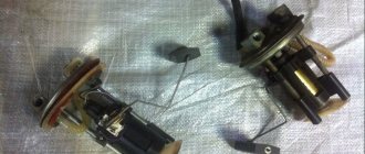
Let's look at the connections of the fuel pump.
In the carb version, two wires approached the tank
The fact is that in a carburetor circuit, the external fuel pump is located in the engine compartment, and these wires simply go to the gasoline level sensor. One, blue and red, supplies voltage, the second, pink, transmits information about the presence of gasoline. In this case (injector), we have a fuel pump in the tank. and it is connected using a block. In order not to pull unnecessary wires, you should do this: connect the old wires to the block as shown below. Now we have connected the power to the fuel pump and the contact indicating the fuel level. We throw the black and white wire to minus. those. frame. The blue-red wire is not needed. Everything in the gas tank area is connected.
Now let's look at the connection in the instrument panel area. Previously, the old contacts (power supply for the level sensor and signal) were connected via a mounting block to the instrument panel
those. We do not touch contact 11 of the white block. This is the contact that shows the fuel level. But we disconnect pin 11 of the red block from the instrument panel. It needs to be connected to the contact that comes from the COURT harness
Next, we’ll think about how to connect the SUD wiring to the cabin wiring braid. The connection block looks like this
In the diagram it looks like this. Among these contacts there is: 1) red-blue (1 contact according to the diagram) wire is “+12” which is connected in the area of the ignition switch. It delivers +12 and turns on the brain when you turn the ignition key
2) gray (pin 2 according to the diagram) is a car speed signal.
3) white-purple (pin 6 according to the diagram) this is the signal of the Check light
4) red-purple (pin 8 according to the diagram) is a tachometer signal. Low voltage.
5) yellow-black (pin 3 according to the diagram) is fuel consumption.
As far as I understand, the fuel consumption signal and the speed signal are connected to the BC.
Check, you need to look for the tachometer according to the diagram... Unfortunately, I don’t know where they are connected on the standard panel. But you can try by brute force, excluding known contacts. Those. unknown only - in white - 1,2,3,6,7,10 in red - 1,5,6,9,11 in yellow - 1,4,5,6,8 known contacts can be found here
In general, on the Internet I came across the designation of all the contacts of the panel... you have to look for it.
What else is interesting in the engine compartment...
Diagnostic block
Immobilizer block
contacts for the immo tablet and the immo warning light. (If you do not plan to install an immobilizer, then they do not need to be connected)
There are still unknown wires... I don’t know what they’re for... maybe the air conditioner, maybe the BC, maybe something else. Those. in theory they may be correctly conceived, but in practice they are not needed, since there is nothing to attach them to
The strip itself with a relay (there are no relays in the photo) and fuses looks like this -
there are three circuits of relays and fuses: the main one, the fan, the fuel pump.
Well, that's basically all. I think the main points will be clear... And you can figure out the subtleties yourself
I would like to answer that I have not personally tested this in practice, so I could be wrong. Its own system, which runs on January 7.2. I implemented it.
Regarding this system January 5.1. I think we’ll check it out soon... for now this is just my theoretical justification. If anyone has any additions or can point out errors, please leave comments.
Injection motor
As for injection internal combustion engines with injectors, their malfunctions, as practice shows, are usually associated with failure of the sensors or the electrics themselves.
To diagnose the cause of the malfunction, do the following:
- first of all, you need to disconnect the power wire from the sensor you suspect;
- after that, using an ohmmeter, you need to measure the resistance on the contacts;
- the resistance value must be checked with the nominal value, which should be indicated in the service book for the car.
Preparation
Fuel level sensor FLS for VAZ 2108, 2109, 21099 cars
At the preparatory stage, which is short but very important, it is worth completely de-energizing the car by disconnecting the battery. You also need to remove all hoses, speed and clutch sensors
Be sure to drain the oil from the engine crankcase and the liquid that cools the radiator. Removing the engine without removing the gearbox:
- first of all, you need to put a reliable support under the car, preferably wooden stumps;
- unscrew the left crab, move the stretcher to the side;
- remove the generator from the engine;
- remove the tensioner pin, pump, distributor and receiving pipe;
- do not forget to remove the head if you are planning a major overhaul;
- the motor must be removed from the box and lowered to the floor;
- in order to get the engine, you need to raise the front part higher (this is done using a jack);
- you can also just pull everything through the top.
How to remove the engine from the gearbox:
- The first thing you need to do is turn off the power to the car. To do this, disconnect the battery. It’s easy to check the lack of current, try turning on the wipers;
- Drain the oil from the engine crankcase. A warm engine will speed up the process;
- drain the coolant from the cooling system, here you need a cold engine;
- get rid of the engine crankcase and exhaust pipe protection;
- carefully disconnect all hoses;
- Next, you need to unscrew the ground wire fastening nut. Next, you can safely turn off the thermostat;
- disconnect the central high voltage from the ignition distributor. To do this, you need to release the pad lock and remove it;
- remove the drive cable from the clutch lever;
- next, you should disconnect the starter supply wires;
- turn off the generator;
- disconnect the wires from the coolant temperature and oil pressure sensors;
- further work will take place under the car. To make it as comfortable and safe as possible, it is worth acquiring an overpass;
- At this stage, unscrew the drive rod mounting nuts. Disconnect the speedometer drive rod, disconnect the power wires;
- disconnect the two braces, tie rods and ball joint from the lever;
- Move the upper tail of the drive a little and push it out with a pry bar. Insert the technological plug into the vacant space;
- Next comes the stage of dismantling the engine. We fix it with a strong rope using the eyelets (rings). It doesn't hurt if you take the time to check their strength first;
- It is best to remove it through the top, but you can also get it through the bottom. Then lower the engine to the floor and lift the front of the car using a jack;
- After you have secured the engine with ropes, you can reach it through the top.
Remember that you need to act extremely carefully so as not to lose the motor, scratch the body, or damage parts. As you can see, the process is very complicated.
Successful dismantling is possible only if all points of the instructions are followed, you have deep knowledge, extreme caution and no haste.
Video "Interactive Wiring Diagram"
From the video below you can see the interactive wiring diagram in the “nines” (author - channel stups87).
In order to independently understand a car, you need to have knowledge of its structure and the principles of operation of certain elements. The VAZ 2109 injector is a set of electronic elements that ensure uninterrupted engine operation. Without it, he becomes just a useless pile of metal. The VAZ 2109 injector is an engine control system, so the wiring and its individual elements must be in good working order, and their operation must be correctly adjusted.
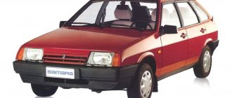
Modifications of VAZ-2109
VAZ-2109 . The basic model, which was produced from 1987 to 1997, was equipped with a 1.3-liter VAZ-2108 carburetor engine with a capacity of 64 horsepower.
VAZ-21091 . Modification of a car with a derated VAZ-21081 engine, 1.1 liter and 54 horsepower. It was mass-produced from 1987 to 1997.
VAZ-21093 . Modification of a car with a VAZ-21083 carburetor engine, 1.5 liters and 73.4 horsepower. Serially produced from 1988 to 2006.
VAZ-21093i . Modification with a VAZ-2111-80 injection engine, 1.5 liters. the first prototype appeared in 1994, mass production began in November 1998.
VAZ 21093-22 . Model made specifically for the Finnish market. It features improved interior trim, pre-installed alloy wheels and a new dashboard. The car was equipped with a 1.5 liter injection engine. Produced from 1995 to 1998.
VAZ-210934 . An all-wheel drive SUV with a VAZ-21093 body mounted on a Niva frame, on which the suspension, steering, engine, gearbox and transfer case from the same VAZ-2121 Niva model were already installed.
VAZ 2109-90 . A variant of the car, which was equipped with a compact two-section Wankel rotary piston engine with a volume of 654 cm3.
VAZ-21096 . Export modification of the VAZ-2109 for countries with left-hand traffic, the steering column was located on the right.
VAZ 21097 . Export modification of VAZ 21091 with right-hand drive.
VAZ 21098 . Another export modification, but this time the VAZ 21093 model with a right-hand steering column.
VAZ-2109 Carlota . A car produced from 1991 to 1996 in Belgium by Scaldia-Volga.
VAZ-21099 . The next independent car model, which is a modification of the “nine”. This car had a 4-door, 5-seater sedan body and a rear overhang extended by 200 mm.
Device
The electrical circuit of the VAZ 2109 with distributed fuel injection is much more complex than carburetor models. This is quite logical, since the injector itself assumes the presence of electronic devices. Any electrical circuit is designed to solve a number of problems. The VAZ 2109 distributed injection system diagram solves the following problems:
- Transmission of signals about the status of parameters;
- Transmission of control impulses;
- Electrical protection of devices;
- Protection of the system from short circuit.
Based on the functions performed, the design of the system must be necessary and sufficient for their implementation.
Transmission of parameter status signals and control pulses
The electrical signal in the VAZ 2109 engine control system is transmitted to the electronic unit via wires that are color-coded accordingly. This makes it easier to read the electrical diagram and find the correct wire. Necessary conditions to ensure high-quality signal transmission are:
- Required wire cross-section;
- Minimum contact resistance of detachable connections;
- Electric strength of conductor insulation.
The operation of the engine, and therefore the dynamic characteristics of the VAZ 2109 engine, determines the state of the wiring.
Reducing the cross-section of the conductor reduces the power of the signal transmitted by it and increases its temperature. Even if the destruction of the veins is not noticeable from the outside, this does not mean that it does not exist.
During the operation of the car, the wiring is exposed to destructive factors. Over time, contacts oxidize. For this reason, their resistance increases, which necessitates periodic cleaning.
Distorted signals introduce inaccuracy or interruptions into the operation of the entire VAZ 2109 system. In order to ensure noise immunity, the oxygen sensor, knock sensor, crankshaft position sensor and the anti-theft system unit are equipped with shielded wires.
Electrical protection of elements
Failure of any injector device may result in replacement with a new one. This is accompanied by material costs. If there are several such devices, then the costs increase many times over. In addition to replacement, tuning may be required. In this case, in the absence of the necessary knowledge, you will need to contact specialists.
The fuses of the VAZ 2109 multipoint injection system have a smaller cross-section than the rest of the wiring. Therefore, they burn out when the current exceeds their rating, thereby protecting the wire insulation and system elements from bad consequences. The injector electrical circuit contains the following fuses:
- Main relay;
- Electric cooling fan;
- Gasoline pump.
Blown fuses should be replaced and the cause that led to this must be found and eliminated.
However, not only fuses provide protection, but also electromagnetic relays. Galvanic isolation of signals allows you to separate low-current and power circuits. This property plays a big role in management. The system contains a main relay, a fuel pump relay and an electric radiator fan.
Short circuit protection
Car wiring is characterized, among other things, by the electrical insulation strength. The latter depends on the condition of its material. Over time, the insulation becomes brittle and microscopic cracks appear. When testing, the wiring may be in good order, but while the car is moving, it may fail to ground. A short circuit is possible between two or more wires.
Vehicle handling
So, with the first two categories everything is very clear:
- Every owner understands what a loss of car control can result in.
- All identified breakdowns are immediately eliminated by repair or complete replacement of parts.
However, the wiring is not so simple. For some reason, everyone is accustomed to thinking that underhood wiring does not pose any danger. But this is a very big misconception.
The short circuit and ignition of live wires threatens that the car may simply burn out, explode, etc. And all this can happen both while parked and while driving.
Underhood wiring includes the following categories:
- Ignition system wires.
- Lighting systems, side lights.
- Connection system for sensors and control unit.
- Wires that are responsible for the operation of the electric motor of the radiator, washer, windows, and wiper.
If the wiring is in good condition, all current-carrying parts are insulated and qualitatively fixed in the engine compartment, taking into account all the necessary physical and temperature indicators of the internal combustion engine.
However, during vehicle operation, fastenings may deteriorate, which will entail:
- Loose contact.
- Destruction of insulation upon contact with hot surfaces of the engine and commutator.
- Formation of abrasions and exposure of wire cores.
- Oxidation of contact connections due to which the “mass” may disappear.
Most owners of the VAZ-2109, as well as other modifications of the domestic automobile industry, independently repair damage in which electrical tape is a direct participant. However, this is only a temporary solution and is not suitable for permanent operation of the machine. If there are problems with the wiring, the best way out of the situation is to completely replace it. According to the instructions, the harnesses must be laid in a corrugation, which is not the case on most machines.
Useful tips
Following simple recommendations will extend the life of the wiring and simplify the life of the car owner.
It is worth periodically looking under the hood of the car and checking the condition of the insulation and connectors. If broken wires are detected, their further destruction and short circuit should be prevented. This can be done using electrical tape or heat shrink. If the wire is literally hanging by a thread, then it is necessary to strip the ends, tin and solder. Then it is good to isolate the connection. Poor contact in the connectors must be eliminated. You can use pliers. Clean oxidized surfaces with a special product, WD-40 can be used. A good engine crankcase protection protects the wires from moisture, so it is necessary. Oil-contaminated insulation deteriorates faster. The use of corrugation to protect against this would be useful. It is better to replace the old wiring, since in this case the risk increases.
When deciding to make major modifications to their car, or restoring it after serious breakdowns, many motorists are faced with the need to replace the wiring. In the design of any car, it is possible to replace either the under-hood wires, mainly coming from the injector, or the interior electronics that ensure the operation of application devices. In today’s article we will look at the features of repairing and replacing both types of wiring, taking VAZ cars as an example. Interesting? Then be sure to read the article below to the end.
How does a fuel pump work?
There is nothing complicated about the fuel supply system. A conventional pump, which is driven by the rotor of an electric motor. To protect the entire fuel system from small particles, a filter is used. But this is not the end of the features, because it is worth noting that it is necessary to maintain the pressure in the ramp at the same level. And the VAZ 2109 fuel pump (the injector simply cannot work without it), provided that it constantly pumps gasoline, will begin to pump up the pressure higher and higher. And this will disrupt the operation of the system.
Features of injection wiring
The appearance of an injection engine power system was marked by a real breakthrough in the automotive industry. Not only have cars with internal combustion engines begun to consume noticeably less fuel, but it has also become possible to fine-tune them to a specific operating mode by adjusting the injectors. However, this state of affairs also affected the complexity of building vehicles. More precisely, the number of different electronics in the design of an injection car has become noticeably larger, and the wiring diagrams have become much more complicated.
This is due to the fact that the injector is a fine-tuning unit that requires broad information about the operation of many vehicle components. This aspect of the functioning of the injection system affected the addition of many sensors to its structure, working in conjunction with the head unit (electronic control unit). To clarify this point, we highlight the following new devices in the design of injection machines:
- Crankshaft position sensor, necessary to regulate fuel injection into the engine;
- Mass air flow sensor installed to adjust the composition of the fuel mixture;
- Knock sensor, with which the ignition timing is adjusted;
- Throttle position sensor, required for the injector to respond to pressing the gas pedal;
- Idle speed regulator, responsible for stable operation of the engine at idle speed;
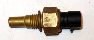
- Temperature sensor that evaluates the temperature of antifreeze in the engine;
- A speed sensor, thanks to which the electronic control unit (hereinafter referred to as the ECU) selects the composition of the fuel mixture.
In addition to the general complication of the system, there were some simplifications in the design of the car. Perhaps the main one was the elimination of some elements of the ignition system. To be more precise, the distributor and coil have become more primitive components, being responsible solely for spark generation, while control of the spark supply has completely passed to the ECU.
Note that the complexity of the interior and engine compartment wiring of cars depends on many factors. The main ones include the make of the car and the equipment of a particular model. That is, the more functionally equipped a car is, the more electronics there are in its design and the more complex its connection diagram. In today's material, our resource decided to consider a not particularly complex system for connecting the wiring of the injector and other devices on VAZ cars. We'll talk about this in more detail later.
How to adjust the fuel supply process using an electrical circuit?
According to the scheme described above, fuel regulation in a car is carried out. Moreover, it depends not only on the load of the valves in the engine, but also on the corresponding position relative to the throttle valve. With the help of a diagram of electrical wiring and valves, it is possible to understand which of the relays or fuses is malfunctioning and replace it in time. In this case, one of the main roles when supplying fuel is played by electrical equipment (controllers) that regulates the operation of the injector.
Basic tips for working with automotive electronics
Let’s immediately agree that installation, removal and any other work with car wiring are the most complex operations, which are taught in secondary specialized educational institutions. This article is for informational purposes only on working with the electronics of VAZ models and contains solely a description of the basic aspects of these procedures, so it will not be possible to learn from it all the intricacies of wiring repairs. Familiarization with these lies only through long and hard work associated with work practice in the field of automobile repair.
Returning to the main topic of today’s material, it would not be out of place to note: even a person without special skills in this path has the opportunity to install the wiring of any car with his own hands. However, for proper implementation of all procedures it is extremely important:
- Have the necessary diagrams that connect the wiring to a specific engine and dashboard. You can find them either when purchasing certified parts or the machine itself, or on the World Wide Web;
- Know the basics of working with automotive electronics, which we will get acquainted with in this article;
- Find free time, a small amount of tools and a place for repair work.
A few words about the procedure for working with wiring
At the end of today’s article, we’ll look at exactly how you should proceed if you want to change the wiring. As an example, let's take standard models of the VAZ brand - 2110, 2109 and the like. So, to competently work with car data electronics you will need:
- First, prepare for repair procedures. The implementation of this goal lies through:
- Purchasing the required wiring and devices;
- Search for the necessary connection diagrams;
- Selection of auxiliary tools: harnesses, fasteners, gloves for work, etc.
- After this, acting according to the diagrams of the currently installed electronics, we completely remove it. Naturally, before this you need to turn off the engine, disconnect the battery and put on gloves;
- Then the actual replacement of the VAZ wiring begins. Here you also need to act taking into account the connection diagrams. First of all, we connect the injector wiring according to the principle “from the oldest element to the youngest”. Next, we connect the main wiring outputs (ECU contacts) with the current source, and at the end we connect other electronics.
Of course, the noted procedure is only generalized, but, in general, compliance with it and compliance with the described rules for working with car wiring is the key to the success of such repairs. We hope that today's material was useful to you and provided answers to your questions. Good luck in maintaining and operating your car!