One of the most complex electrical devices in a VAZ 2109 car on the injector system is undoubtedly the ignition module. This element is found in injection cars; for carburetor cars, an ordinary coil is installed. In fact, the ignition module performs only one, but very important function - it generates a high voltage current, up to 30 thousand watts. Next, the current is directed through high-voltage wires to the spark plugs, and they produce sparks that ignite the fuel in the cylinder block.
The traditional coil is also part of the ignition module, but is only one of its components. In fact, the design of the device is much more complicated.
Let's look at it using an example of how the VAZ 2109 ignition system works on an injector system.
VAZ 2109
Possible reasons for failure of the ignition module
Before repairing the main part in the car’s ignition system, you need to understand the nature of the problem. To do this, the consumer must be aware of the signs of a malfunction, as well as the causes of the breakdown.
The main reasons for device failure
Causes of problems:
- The ignition system uses spark plugs that do not match the vehicle parameters. They may not have the gap specified by the manufacturer. Also, the spark plugs themselves may not be working or dirty; this can be determined by visual diagnostics. If there are traces of carbon deposits on the devices, they must be removed.
- Malfunctions in the operation of the MH can arise as a result of frequent spark checks. At the time of diagnosis, a high load is placed on the device. If it appears frequently, it will lead to equipment failure or incorrect operation.
- The ignition module in the VAZ 2114 operates with the high-voltage cables disconnected. This also leads to device failure. The products themselves may be damaged, which affects the functioning of the engine as a whole.
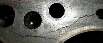
- The device operates under severe vibration conditions. Their impact may be due to poor quality fixation of the module in the seat. As a result of vibrations, the factory soldering inside the equipment structure is damaged. This leads to its incorrect operation.
- The contact inside the plug with the low-voltage cables is broken.
- Initial use of a defective device or module with poor build quality. This factory defect can only be eliminated by replacing the mechanism; repairing the equipment is pointless.
- Moisture getting inside the case. This problem is unlikely, but exposure of the device to liquid may cause it to short out and break.
Signs of coil malfunction
The main symptoms of a malfunction in the VAZ 2114 ignition module:
- Difficulties arise when trying to start the engine. Starting the car engine may be difficult due to the fact that there is no spark on a spark plug or several.
- When idling or parking with the internal combustion engine running, the speed of the power unit floats. Their change is not associated with pressing the gas pedal and other third-party factors. This happens randomly.
- There are dips in the power of the car's engine. This is especially felt when driving uphill or sharp acceleration. Problems can also occur when driving on a flat road.
- Several cylinders stopped working. Usually these devices operate in pairs, so elements 1-4 or 2-3 could fail. Non-working cylinders may be indicated by “triple movement” of the engine.
- A “Check Engine” warning light appeared on the dashboard.
If the ignition module malfunctions, problems will appear not only in engine operation, but also when starting it.
The “Simple Opinion” channel, using the Lada Priora car as an example, spoke in detail about the symptoms that appear in the operation of the ignition modules.
Features of the engine compartment
Let's find out what is dangerous under the hood for the operation of the wiring and the consumers it connects to the electrical network.
First of all, you should realize that all the most important components and assemblies that have high physical and chemical indicators are concentrated in this enclosed space:
- The power unit
is a source of increased heating of nearby components and assemblies; - Power supply system
– explosive vapors of the air-fuel mixture; - Power elements of the electrical circuit
- numerous electrical connectors and connections: relays, - electric motors for windshield wipers and washers,
- headlight ignition units or self-installed fog lights to improve visibility on the road.
Therefore, if the technical parameters of the wires have deteriorated, as evidenced by oxidation of contacts, delamination of insulation, numerous twists, etc., it must be replaced as quickly as possible. Of course, unless you have one that initially has better parameters.
How to check the malfunction of the VAZ 2114 ignition module on your own?
The easiest way to check the device without removing it is to diagnose it at the moment the power unit is tripped. When the motor begins to operate unstably, it is necessary to disconnect the connector elements from each component of the module one by one. If the connector is disconnected from a functioning device, the operation of the engine will change. Dips will appear, and the unstable operation of the unit will increase. When the non-working element of the MH is disconnected, the motor will operate in the same way.
There is another simple diagnostic method, its principle is as follows:
- You will need an assistant to check. The spark plug is removed from the seat. The high-voltage cable is disconnected from the device.
- Then the disconnected wire is connected to a spark plug, which is applied to the body of the power unit.
- The machine motor is starting, you need to make sure that a spark hits the spark plug. If it passes, a blue light will appear between the device and the surface of the power unit, its formation is accompanied by a crackling sound. If there is no spark, then the spark plugs, high-voltage cable and module must be diagnosed.
In the absence of special equipment, diagnostics of the MH can be performed using a control light indicator designed for 12 volts. One conductor from the lamp is connected to the pin of connector A, and the second is connected to ground for grounding. An assistant must start the power unit or rotate the starter mechanism. If the light flickers when performing these steps, then the device is working. Similar actions must be done with another contact.
The channel “Diary of an Auto Electrician” spoke about self-diagnosis of ignition modules, as well as other elements of the system.
Checking the ignition unit with a multimeter
Diagnostics is carried out in the following order:
- The car engine is started.
- The tester switch must be set to DC measurement mode, the limit should be up to tens of volts.
- One of the contacts of the multimeter is connected to connector D on the coil, and the other goes to ground. You can use a car body or a cylinder block as a mass. If there is power, the diagnostic tool display will show 12 volts.
- Then the tester switches to the ohmmeter operating mode, the range of values is up to tens of ohms.
- One contact of the diagnostic tool is connected to output C, and the second goes to ground. If the device is operational, the test will show a value of less than 1 Ohm.
- At the next stage, the tester must be switched to voltmeter mode. The range of values is up to tens of volts.
- One of the contacts goes to the output marked B, and the second is connected to ground.
- If the diagnostics show that the voltage is less than 0.3 volts, then the device is working. This indicates a clear signal passage from the Hall controller. Finally, you can perform a similar test, only with connector A. The results should be identical.
Engine compartment modifications
Car diagram
In addition to replacing the power unit after it has exhausted its life, there are many components in the engine compartment whose wiring also needs to be replaced:
- high-voltage wires from the ignition unit;
- wiring of various control sensors;
- battery power cables (connections are most susceptible to corrosion).
If there is no spark, repair of the electrical wiring of the VAZ 2109 is inevitable.
Numerous sensors in the engine compartment require special monitoring:
- Coolant temperature sensor - if the electrical wiring is faulty, the driver will not notice overheating of the power unit;
- Brake fluid level sensor in the expansion tank - a leak or low level can lead to brake system failure;
- ABC system sensors - oxidation of contacts or disruption of wiring integrity can lead to system failure;
- Exhaust gas sensor - based on its readings, the electronic unit “prepares” the fuel-air mixture. If the sensor does not work, gasoline consumption will increase.
The only wireless car security alarm element
A useful addition to the functionality of the car is the acquisition of a modern anti-theft system.
Installing a modern alarm system is a special topic, since its work affects several main components and systems of a VAZ family car:
- General electrical system;
- Supply system;
- Sound and light circuit and actuators (side lights, headlights, sound signals);
- Standard immobilizer.
To install an alarm system, a VAZ 2109 wiring diagram is required
General alterations
Installing additional fog lights is a general modification because:
- Affects equipment in the engine compartment;
- Interferes with the instrument panel inside the cabin;
- Connects to the vehicle's standard power supply system;
- Attached to the power body.
The kit must contain connection instructions
To install and connect fog lights, you will need a wiring diagram for the VAZ 2109, because the package includes:
- Connecting wires;
- Terminal blocks;
- Switching relay;
- Actuators (buttons);
- A backlight lamp (or LED) indicating the status of lighting fixtures.
For what malfunctions is it possible to repair the device?
Due to the fact that the ignition module by design includes a connection of two coils, it is difficult to repair. If there is a break or breakdown, as well as melting of the turns, the problem can be solved by replacing the device. This applies to any damage that appears inside the coils. The only option to correct the situation without replacing the device is to repair the damage to the solder joint.
Ignition module repair process
The repair procedure is carried out after preparing all tools and materials:
- a set of socket wrenches, you will need a tool for 10, 13 and 17;
- hexagon 5;
- flat head screwdriver;
- soldering iron with aluminum and flux;
- nail polish;
- multi-core conductors.
Restoring the ignition module operation is done as follows:
- The key is installed in the switch. The engine starts. Then you need to move the contact elements on the module to make sure they are not working.
- The power unit stops. The module is being removed.
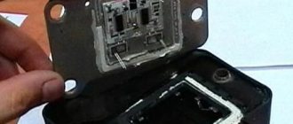
- The device body is cleaned from dust. To disassemble, you need to open the case; this is done by prying it off with a screwdriver. Inside the device there is a board on which there is a silicone film; you need to get rid of it.
- Aluminum is removed from high-voltage contact elements. Old wires are removed.
- The next step will be soldering new conductors to the circuit. To do this, the surface of the collector device is cleaned from traces of plaque. Then the board must be installed on an electric stove and heated to approximately 200 degrees. As the temperature increases, a slight burning smell may be heard. This is not a problem for the circuit; heating it will simplify the soldering procedure.
- Then soldering is done. Using a soldering iron, flux and aluminum, the ends of the conductors must be connected to the ignition module. All contact elements of the conductors that are connected to the circuit must be treated with nail polish.
- Then the device is assembled in the reverse order and installed in the seat. After installation, the power unit starts up. If the repair solves the problem, then using a sealant, the device is fixed in place.
- If a transistor or switching device fails, then these components cannot be repaired, but they can be replaced. To do this, the parts are removed from the board and replaced with new ones.
Ilya Balashov presented a video with the result of soldering the ignition module using the example of a VAZ 2110 car.
Historical excursion
Gearbox of a ZIL-130 car shift diagram. Zyl automatic transmission
The famous “nine” rolled off the assembly line for the first time in 1987 and remained on the assembly line until 2006 (in the CIS countries - until 2011).
It was offered to buyers with three power units:
- The model with a 1.1-liter carburetor engine was called VAZ-21091;
- The same, but with a more powerful 1.3 liter - VAZ 2109;
- The most powerful modification (80 hp) bore the VAZ-21093 designation and was equipped with a 1.5-liter engine.
Wiring diagram for a VAZ 2109 to a carburetor: solenoid valve control system.
Producing countries
And, nevertheless, today on Russian roads you can find different years of production of VAZ 2109 cars.
In addition, many cars of this family were produced abroad:
- In Ukraine, production was carried out by the ZAZ automobile plant (Zaporozhye);
- In Finland, the VAZ 2109 model was produced in the town of Uusikaupunki at the Valmet plant. The car received a new name for the European market – Samara Baltic.
Samara Baltic – photo from the stand of the Frankfurt Motor Show 1995
Family Samara Baltic
Finnish-assembled cars also found their way onto the Russian market. They were distinguished from domestic cars:
- Window lifters;
- Hydraulic power steering (power steering);
- Sunroof;
- New instrument console;
- Sound system in the cabin.
The contactless ignition system was equipped with imported wires
Naturally, the wiring diagram of the VAZ 2109 to the carburetor was redesigned by Finnish engineers taking into account new devices.
In particular:
- The carburetor version had electronic components from European manufacturers;
- The L package had a different, specially designed instrument panel (the video of the interior in advertising always made domestic car owners want to get it);
- In addition to the panel, the GL package was equipped with fog lights and an additional brake light in the rear spoiler.
Wiring diagram for a VAZ 2109 on a carburetor with a block from GM
The price of a Finnish instrument panel simply went through the roof in thrift stores
Models equipped with:
- central injection (injector) from General Motors;
- catalytic converter in the exhaust system;
complied with EURO 2 requirements and were sold exclusively in Europe. Carburetor models were shipped to the USSR under contract and were distinguished by the highest quality paintwork.
Let's also understand the intricacies of the VAZ 21074 injector wiring diagram.
Control electronics from General Motors are not uncommon on cars from Finland
Replacing the ignition module of a VAZ 2114
If repairing the MZ VAZ 2114 is impractical or impossible, then the problem with the operation of the device can be solved by replacing it.
The equipment needs to be changed only when the battery is disconnected. Otherwise, there is a risk of short circuits and failure of other electrical appliances.
How to remove the ignition module of a VAZ 2114?
The dismantling procedure is performed as follows:
- First, the on-board network is de-energized; to do this, loosen the negative clamp on the battery with a wrench.
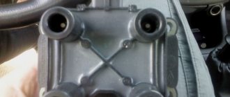
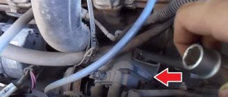
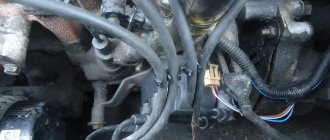
- Then a search for MH is performed in the engine compartment. You can find the device by four high-voltage wires that go from the spark plugs directly to the equipment. These cables are disconnected from the MH.
- Then the connector with conductors is disconnected from the device. It is necessary to disconnect the fixing fastener located on the ignition module housing.
- The MZ itself is secured to the bracket thanks to three nuts. You need to unscrew them using a key.
- After dismantling the fasteners, the device located on three studs is removed.
Connecting a new device
The equipment installation procedure is performed in reverse order; during installation, the following nuances must be taken into account:
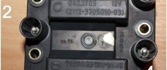
- After installing the ignition module, you need to look at its surface. It is marked with numbers - 1, 2, 3 and 4. These symbols indicate the numbers of the cylinders to which the MZ should be connected.
- To properly connect the device, you need to look at the ends of the high-voltage cables. They are also marked with the same numbers. This is done in order to simplify the procedure for connecting the MH to the cables.
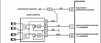
Connection diagram
The device must be connected in accordance with the diagram given in this section.
What should I do if the problem remains after replacing the module?
If, after performing the repair, problems in the operation of the MH remain, then there is a possibility that the cause of the problem was not in the module. It is necessary to diagnose the remaining elements of the ignition system.
Spark plugs and ignition system
Features of checking spark plugs and other components:
- Before dismantling the devices, it is necessary to disconnect the ends of the high-voltage cables. Their condition is checked for damage. Defects in the tips often lead to malfunctions in the spark plugs. If there is damage, the wires are replaced. It is also necessary to assess the condition of the “high-voltage workers” themselves. They are not allowed to have any defects or damage to the insulation.
- After disconnecting the tips, the spark plugs are dismantled and a special spark plug wrench is used to unscrew them.
- After dismantling, the condition of the devices is assessed. The color of the parts must be brown; carbon deposits and soot on the electrodes are not allowed. If there are uncharacteristic marks, the devices are cleaned using a metal brush or fine-grained sandpaper. For a better effect, the electrodes of the candles can be heated on the stove.
- The condition of the gap between the part and the electrode element is checked. If it is too large, this indicates that the device is not working correctly. The spark plugs will need to be replaced.
Problems in the system and their causes
There are several signs that you need to adjust the VAZ ignition on your Nine:
One of the signs that the VAZ 2109 ignition system is not working correctly is a late engine response to turning the key. In other words, the engine takes a long time to start or does not start the first time
Such a malfunction is the first reason to check all components of the system and replace damaged ones. You should also pay attention to fuel consumption. If the amount of fuel consumed has recently increased, it means that the ignition cycle is broken and needs to be adjusted. And the last, most alarming signal is the occurrence of detonation
Due to the early appearance of the spark, the fuel burns unevenly, causing the engine to overheat. During detonation, burnout of the cylinder and piston is often observed.
This occurs for the following reasons:
- In the first case, the spark has insufficient charge to ignite the mixture, which makes it difficult to start the engine. It is necessary to check the spark plugs and other elements of the system.
- Fuel consumption increases due to the fact that the ignition fires later than necessary. It takes a certain period for the mixture to ignite and burn, so the spark must ignite the fuel in time. With late ignition, the mixture burns later and longer than required, which is why the piston mechanism cannot operate at full capacity. As a result of this effect, engine efficiency decreases and fuel consumption increases.
- Another case is when the spark occurs too early and the mixture burns prematurely. There is also a noticeable drop in efficiency, but now it is accompanied by engine overheating. Since the cycle of movement of the piston and the combustion of the mixture do not coincide, the energy of their work will be spent on mutual extinction, resulting in heating of the working parts.
Video “Visual guide to replacing MH”
The STO TONN channel presented a visual aid for replacing the ignition module on a domestic VAZ 2114 car.
Due to a malfunction of the ignition module, the following malfunctions may occur in the operation of the injection engine of VAZ 2108, 2109, 21099 cars: the engine “triples”, “doubles” (works or tries to start on two cylinders), unstable idling, “dips”, “jerks” , “twitching”, etc.
— Multimeter, autotester or other device with ohmmeter and voltmeter modes
— Socket wrenches or heads for “13” and “17”
Preparatory work
— Remove the ignition module from the engine
Disconnect the ends of the high-voltage wires. Use a key set to “13” to unscrew the two upper fastening bolts, and use a key set to “17” to loosen the tightening of the bottom bolt. Remove the module along with its bracket.
— Cleaning from pollution
Wipe with a dry cloth.
The procedure for checking the ignition module (coil) of the ignition system of VAZ 2108, 2109, 21099 cars with an injection engine
In garage conditions, you can check the secondary windings of the ignition module for an open circuit and the primary windings for a short circuit, as well as the voltage supply to the module from the ECU. This is quite enough to diagnose the problem.
— Check for short circuit
The positive probe of the multimeter in ohmmeter mode to terminal “D” of the ignition module connecting block, the negative probe to the bracket (“ground”). If there is no short circuit, the device readings tend to infinity.
— Check for “break”
Using a multimeter in ohmmeter mode, we alternately measure the resistance between terminals “1” and “4”, “2” and “3” of the ignition module.
The resistance for each measurement should be within 4 kOhm. If it is different or does not correspond to the required indicator, the module should be replaced.
— Checking the voltage supply to the ignition module
If previous checks did not reveal a malfunction, you need to check the voltage supply to the ignition module. Turn on the ignition. Using a multimeter in voltmeter mode, measure the voltage between terminals “C” and “D” of the block of the wiring harness going to the module (the terminals are marked on the block itself). The voltage must be within the vehicle's on-board voltage (12V). If it is smaller or absent, then the battery may be discharged, the wires from the computer to the ignition module are faulty, or the control unit (ECU) is faulty.
Notes and additions
— Often, one of the visual signs of failure of the ignition module can be two wet and two working spark plugs, since the module consists of two pairwise connected ignition coils that alternately produce a spark in two cylinders -1-4, 2-3. The failure of one of the coils leads to the engine running (or trying to start) on two spark plugs.
— The problems listed above in the operation of a car engine may be based not only on a malfunction of the ignition module, but also on a malfunction of the spark plugs, high-voltage wires, as well as the power and control system (ECM).
More articles on the ignition system of the injection engine of VAZ 2108, 2109, 21099 cars
Comparative test repair
The VAZ-2114 ignition module is also called a high-voltage coil, which serves to transmit current to the spark plugs. This module has its own signs of malfunction, by which it is necessary to determine when to replace the failed part. What are these signs? This will be discussed in this article.
Video Interactive wiring diagram 2109
Car battery diagram
A detailed interactive diagram of the VAZ 2109 is shown in the video (the author of the video is Alexander Vakhteev).
If your engine does not want to start, then the problem may be in the wiring, if we talk about the VAZ-2109. The fact is that wiring occupies one of the leading places in the car control system. Sometimes it happens that a driver upgrades his car without knowing the consequences. Over time, all sorts of breakdowns arise and the driver simply does not have the nerve to sort out all that chaos. So you have to replace the wiring in the VAZ 2109.
When the question arises of completely replacing the wiring, it is necessary to find all the electrical components, otherwise it happens that you end up with a collection of blocks, wires, switches and sensors of various types.
By replacing the wiring, you can also change the torpedo. Fortunately, there is enough of this goodness on the market. So, to carry out the replacement, we take the wiring from the VAZ 2109 Lux. In my opinion, this is what is needed. It includes: fuse box; size switch and hazard warning button; stove body, air vent sleeves; set of instruments; terminals, wires, blocks, electrical tape.
VAZ-2114 ignition module: various signs of malfunction
Experts note the main symptom of a faulty ignition coil is the absence of an igniting spark on the spark plugs. But, besides this, there are other signs by which one can judge that the module has failed:
- Lack of dynamics during engine acceleration.
- The appearance of failures in the operation of a car engine at the moment of sharply pressing the gas pedal with your foot so that the vehicle accelerates.
- A noticeable decrease in engine power (as they say, “the engine doesn’t pull”).
- “Swimming” of idle speed.
When the first signs of a malfunction of the described module appear, the owner of the VAZ-2114 should diagnose it. This can be done either independently at home or at the nearest service center for repairing cars of this model.
How to diagnose the ignition coil on a VAZ-2114
As already mentioned, when the first signs of malfunctions appear in the VAZ-2114 ignition module, the vehicle owner should diagnose it. You can perform a similar procedure yourself at home using the following algorithm:
- Check the spark plugs.
- Check the crankshaft position sensor.
- Check the ignition coil.
At home, all stages of the checks can be performed independently. The first stage is checking the spark plugs. It is carried out in the following sequence:
- We remove the spark plugs from their sockets - remove the tips of the high-voltage wires (a special spark plug wrench is suitable for this).
- We examine the candles.
- We clean them from possible soot.
- We set the correct distance between the electrodes.
- We check the spark plugs for operation using improvised means (for example, from a device made from a piezo lighter) or on a car engine with a working ignition system.
If the spark plugs are in good condition, you can proceed to the next stage of checking for faults in the ignition module.
The second step is to check the crankshaft sensor. This test is carried out using a multimeter, thanks to which two characteristics are checked - voltage and resistance. To do this proceed as follows:
- Remove the crankshaft sensor.
- Measure resistance:
- a special ohmmeter mode is installed on the device;
- the terminals of the device are connected to the ends of the winding, which is brought to the surface;
- with optimal sensor operation, digital readings will range from 500 Ohms to 700 Ohms.
- Measure voltage:
- switch the device to the mode for measuring alternating voltage;
- terminals are connected to the ends of the winding;
- any handy object made of metal should be passed along the body of the crankshaft sensor;
- When the sensor operates optimally, the device will show increased voltage readings because there will be a metal object nearby.
Otherwise, the faulty sensor will have to be replaced with a new one, because it also affects the operation of the VAZ-2114 ignition module. If after this there are still signs of coil malfunction, then you should proceed to the third stage of the test.
The third stage is checking the ignition coil itself. This part is checked as follows:
- The easiest way is to replace the coil with a new one;
- while the car engine is running, you can move the coil and knock on it (if there are visible changes in the functioning, it is time to judge a faulty contact in the coil itself);
- take measurements with a multimeter for resistance readings, such indicators are taken from paired coils - they should be identical, approximately equal to 5.4 kOhm.
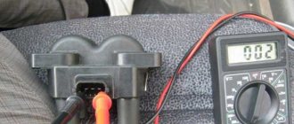
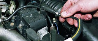
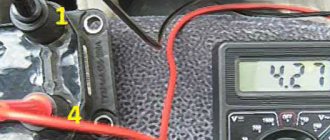
What to do if you don’t have a multimeter, but you need to check the electrical circuit? Experts recommend using a twelve-volt light bulb. To do this, one of the wires coming from it should be connected to the terminal, and the second wire should be shorted to the motor housing. If the control light flickers when the starter starts, then everything is in working order.
If the car owner has problems performing such diagnostics himself, he can always turn to qualified specialists at a service station.
Methods for preventing the ignition module on a VAZ-2114
Malfunctions of automobile ignition coils on the VAZ-2114 can be avoided if preventive procedures are regularly carried out. These include:
- Periodic unraveling of high-voltage wires (associated with greatly increased internal resistance, as this can damage the module).
- Checking the spark gap between the electrodes of the spark plugs (if the distance between the electrodes changes, this will affect the efficient operation of the ignition coils).
If faulty spark plugs are identified, they are replaced, after which the car will function properly again.