The ignition module (IM) of the Niva-Chevrolet car is highly reliable and, most often, provides sparking over many tens of thousands of kilometers. However, if it fails, it is difficult to diagnose due to the lack of obvious signs. The decent cost of a module does not always allow it to be replaced with a new one, which is called “blindly”. First you need to reliably verify that the old one is faulty. Read the article about how to check the ignition module of a Niva-Chevrolet.
Briefly about the design
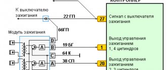
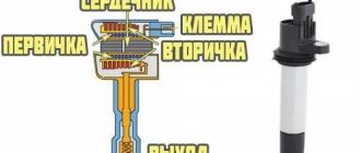
The main purpose of any MZ is to convert a low-voltage signal into a high voltage sufficient for normal sparking in the cylinders. Therefore, structurally, the Niva-Chevrolet ignition module is a pulse transformer. A signal from the electronic control unit (ECU) is supplied to its input, and a voltage of about 20 - 30 kV is removed from the output. The module has a connector for connecting the low-voltage part and four sockets into which the so-called armored wires are inserted.
High voltage is supplied to two cylinders at once. In this case, 90% of the energy is spent on the formation of a spark where the compression stroke ends. The working mixture in it is under high pressure, which means it has high conductivity. Thus, the module consists of two independent ignition coils.
VAZ models 8 and 16 valves
Despite the similarity in engine design, the ignition system of the 1.5-liter injection 16-valve engine differs from the 1.6 16-valve engine. The 1.6 liter engine uses an electronic contactless ignition system with individual coils on each spark plug. Therefore, there was no need for an ignition module. Such a system is more reliable and cheaper to operate, since if one coil fails, there is no need to replace the entire module.
The 16-valve 1.5-liter VAZ 2112 injection engine used the same non-contact ignition system as the 8-valve engine, but a different ignition module was installed. Its catalog number is 2112-3705010. The design of the module remains the same - two ignition coils (for cylinders 1-4 and 2-3) plus switch keys in a single block. The spark is supplied to the cylinders in pairs using the idle spark method. This means that sparking occurs in two cylinders simultaneously - in one on the compression stroke (working spark), in the second on the exhaust stroke (idle spark).
Where is the Ministry of Health located?
The location of the Niva-Chevrolet ignition module was not chosen very well. It is attached to the bottom of the cylinder block. Thus, the module is exposed to two negative factors at once:
- Corrosion. This is facilitated by the low location. During operation, moisture often gets into the MH.
- High temperature. Mounting the module on the cylinder block forces it to operate at temperatures close to 100 degrees.
The second factor is the most critical for MH. The manufacturer guarantees normal operation of the device up to 120 C°. This kind of temperature under the hood is rare. But constant exposure, even to lower values, significantly reduces the service life of the MH. Therefore, conscientious owners move the module to a place with more benign conditions. Most often, on the partition of the engine compartment.
Varieties
During its production, Shniva was equipped with two types of modules.
- MZ from a VAZ 2112 car. Installed until 2006. It includes a spark control system.
- The module is from a VAZ 2111. It is controlled by signals from the ECU, therefore, in essence, it is a regular ignition coil.
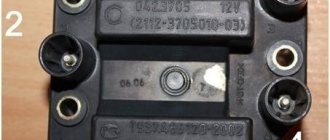
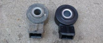
Please note that the modules are not interchangeable. This is due to their different designs. You can determine which ignition module on a Niva-Chevrolet by its appearance. The old one has large dimensions and weight, and most importantly, unlike the new one, there are not three, but four contacts on the primary winding connector. At the same time, the process of checking the Niva-Chevrolet ignition module will be considered using the example of a new module.
Candle making options:
Checking the DPD with a VAZ 2110 multimeter
To increase productivity when creating these products, some technological features are used, which in theory can increase productivity, and as a result, the highest quality fuel combustion:
- Platinum coating. Allows you to increase the service life up to 50 thousand kilometers due to the fact that the surface becomes more resistant to the combustion products of the fuel mixture.
- Multi-contact spark plugs. Typically used in cars that are operated in regions with predominantly low temperatures. Such products make it possible to improve the starting of a cold car in the morning. In summer, it is recommended to replace them with regular ones.
Symptoms of a problem
As already mentioned, symptoms of a faulty ignition module are also typical for many other components of the car. There are almost no signs that directly indicate MH. This significantly complicates repairs. However, with experience, conclusions about a malfunction of the Chevrolet Niva ignition module can be drawn from the following symptoms.
- Two cylinders are not firing at once. This is the only sign that, although not always, indicates MH. The likelihood of this increases if cylinders 1 and 4 or cylinders 2 and 3 are not working at the same time.
- Idle speed “floats”.
- Diagnostics shows misfires in all cylinders.
- As the engine warms up, its power drops and interruptions appear.
- The CHECK ENGIN alarm comes on.
It should be noted that a complete failure of the motor, in which the engine does not start at all, happens very rarely. Basically, this symptom of a malfunction of the Niva-Chevrolet ignition module indicates damage to the low-voltage part of the wiring.
General tips for connecting high-voltage wires.
Ignition module VAZ 21214 signs of malfunction
First, let's decide which of the four cylinders is first?
The first cylinder in front-wheel drive VAZs is located closer to the timing belt. If you look at the engine from the front, the first cylinder is the leftmost). And then everything is simple - from left to right - 1, 2, 3, 4.
In rear-wheel drive VAZ Classic and Niva, the first cylinder is located closer to the front bumper of the car.
Laying wires. Do not try to connect the wires in a bundle. Disassemble the wiring harnesses, release the wires from the plastic holders. Connect the high-voltage leads to the corresponding cylinder spark plugs. Lay the wires so that they do not rub against each other, engine parts, or hoses. Avoid sharp bends and tension on the wires. After connecting all the wires, secure them into the bundle with special comb holders included in the delivery kit.
The procedure for connecting I/O wires to a VAZ carburetor (2108, 2109, 21099)
The central wire from the distributor cover always goes to the ignition coil (bobbin).
The outlet of the distributor cap, looking down, is connected to the third cylinder.
The outlet of the distributor cap, looking rearward, is connected to the fourth cylinder.
The outlet of the distributor cap, looking up, is connected to the second cylinder.
Central wire from the ignition coil (bobbin)
1 cylinder - above the vacuum corrector. Next, clockwise, the order is 1-3-4-2.
Actually, on the module body it is already indicated which cylinder the pins correspond to - but we duplicated them in red in case the module gets completely dirty, and you might not be able to see it in the photo.
Injection VAZ produced after 2004 with a new ignition coil (3-pin low-voltage connector)
As with the old-style ignition modules, the new coils are also marked with pins corresponding to the cylinders. But the connection order is different from the order on the old-style ignition module. Be careful.
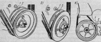
The arrow shows the direction of rotation of the ignition distributor.
For normal engine rotation, the working mixture in the cylinders is not ignited in the usual order of 1-2-3-4. The high voltage wires are inserted into the ignition distributor according to the firing order. To avoid confusion, new high voltage wires are numbered. The ignition order for all types of engines is the same: 1—3—4—2.
Causes of damage
Most often, the Niva-Chevrolet ignition module fails due to overheating caused by its poor location in the engine compartment. This simply leads to a break in the secondary winding of the pulse transformer. However, this can happen for other reasons, namely:
- use of faulty high-voltage wires;
- use of spark plugs other than those recommended by the manufacturer;
- checking the spark by shorting the armored wire to the car body;
- manufacturing defects.
Peculiarities
The operation of the Niva 21213 system depends on the condition of its parts. High-voltage wires must have a distributed resistance, the value of which is in a certain range. Too much resistance will result in the ignition coil not having enough power to cause a breakdown. Low resistance increases interference. Although, some install just such wires. Of course, the spark power will increase and engine performance will improve. Spark plugs can lose their properties over time. The electrodes melt and carbon deposits appear.
The high temperature inside the cylinders greatly heats the spark plugs. Therefore, even when the ignition is turned off, ignition occurs from heated spark plugs.
It is important that all spark plugs have the correct gap between the electrodes. This will ensure high-quality ignition of the mixture. The distributor cap must be clean from dirt, t
because its presence can lead to current leakage
The distributor cover must be clean from dirt, since its presence can lead to current leakage.
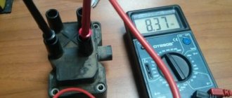
Procedure for checking the ignition module
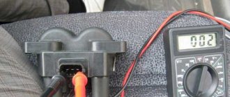
First of all, you will have to get a multimeter. There is no need to look for any high-precision and expensive instruments. The usual Chinese one will suffice. The main thing is that it has a digital display, this will greatly simplify the measurement. The optimal multimeter in terms of price and functionality is the DT 830 and its numerous modifications. This is one of the most common and easy to use devices. The verification process will be discussed using his example.
First of all, you need to make sure that the primary winding of the Niva-Chevrolet ignition module is intact. For this:
- the switch on the front panel of the device is set to the 200 Ohm position;
- disconnect the connector from the module, remove the high voltage wires;
- sequentially measure the resistance between the middle and extreme contacts of the terminal block;
- The device readings should be within 0.5 Ohm.
The accuracy of a multimeter, of course, is not enough to measure such small quantities, but to check the primary winding for an open circuit, this is quite enough.
The next step is to measure the resistance of the secondary. Sequencing:
- set the range switch DT-830 to position 20 K;
- The probes of the device must first be placed between the high-voltage terminals of cylinders 1 and 4, then 2 and 3;
- the device display should display 5.4 kOhm.
It should be said that it is possible to diagnose a malfunction of the Niva-Chevrolet ignition module only if the readings differ significantly from the norm, or, more often, if “1” lights up on the device indicator. This means an infinitely large resistance, in other words, a winding break.
Some gasoline engines that are installed on modern domestic and imported cars are equipped with ignition modules, which are a pulsed high-voltage current source. There are situations when these devices fail, leading to a complete or partial loss of performance of the car engine. Ways to check for a malfunction in the ignition module in a garage are covered in this article.
How to check and identify faults in the ignition coil of a Niva Chevrolet
Let’s try to figure out how to diagnose and identify faults further:
- First of all, you need to disconnect the battery, then remove the plastic casing of the power device from under the hood of the car.
- Having previously studied the order of the wires (if necessary), we turn off the high-voltage ones, disconnecting them from the spark plugs.
- To fully perform the diagnostics, you will need a multimeter (first we measure the resistance of the secondary winding); To do this, the device is connected to high-voltage wires. If the indicators exceed the permissible standards, the coil must be replaced.
- In a similar way, you can check the resistance of the primary winding. The readings should be around 1-2 ohms. When the indicators differ, the coil can be replaced.
When the need arises to change the ignition coil, it is not necessary to immediately go to a service station and pay money for it. You can do this kind of work yourself in your garage without spending too much time on it.
- Disconnect the battery and remove the protection from the motor.
- Having disconnected the high-voltage wires and the block from the output of the coil itself, we unscrew the fixing nuts and dismantle the mechanism.
- Next, you should pay attention to the brand of the reel. When buying a new one, you need to buy a similar brand.
- For more convenient installation, you can try removing the holder, which is secured with three screws. The entire installation procedure is performed in reverse order.
You can also view the procedure for connecting and replacing the coil on the Internet. Many videos allow you to figure out this work yourself and do it yourself.
The ignition module (IM) of the Niva-Chevrolet car is highly reliable and, most often, provides sparking over many tens of thousands of kilometers. However, if it fails, it is difficult to diagnose due to the lack of obvious signs. The decent cost of a module does not always allow it to be replaced with a new one, which is called “blindly”. First you need to reliably verify that the old one is faulty. Read the article about how to check the ignition module of a Niva-Chevrolet.
Design and principle of operation of the ignition module
Some old-school motorists call the modules double-spark coils, which makes sense. After all, the coil is the predecessor of the ignition module in the technical evolutionary chain. The module is a paired design consisting of two pairs of windings (primary and secondary) and a switch that alternately switches low-voltage current from one coil to another. In some models of double-spark coils, the commutator is structurally located outside the block .
The operation of the module is controlled from an electronic unit that collects and analyzes information from various working components of the engine. The block, unlike the classic coil, has 4 sockets for connecting high voltage wires going to the spark plugs. The pulse occurs in pairs, first at terminals 1 and 4, then 2 and 3. That is, each of the built-in coils is responsible for the operation of two cylinders. A spark occurs simultaneously, as a pair.
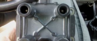
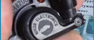
This is what one of the ignition module models looks like. The connector for connecting incoming wires is visible at the top.
At the input, the ignition module has a connector with four terminals. Usually most models have markings opposite them. Pulses from the Hall sensor alternately arrive at contacts A and B, serving as a signal to switch the commutator from one primary winding to another. C and D – ground and power supply (12 V), respectively.
Contact ignition system VAZ 2107
The classic contact system used on the VAZ consists of 6 components:
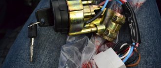
- Ignition switch.
- Breaker-distributor.
- Spark plug.
- Low voltage wires.
- Ignition coil.
- High voltage wires.
The ignition switch combines two parts: a lock with an anti-theft device and a contact part. The switch is secured with two screws to the left of the steering column.
The ignition coil is a step-up transformer that converts low voltage current into the high voltage needed to produce a spark in the spark plugs. The primary and secondary windings of the coil are placed in a housing and filled with transformer oil, which ensures their cooling during operation.
The ignition distributor is the most complex element of the system, consisting of many parts. The function of the distributor is to convert constant low voltage into high pulsed voltage with the distribution of pulses across the spark plugs. The design of the distributor includes a chopper, centrifugal and vacuum ignition timing regulators, a movable plate, a cover, a housing and other parts.
Spark plugs ignite the gasoline-air mixture in the engine cylinders using spark discharges. During operation of the cross sections, it is necessary to monitor the gap between the electrodes and the serviceability of the insulators.
Possible causes of failure
The weak point of the ignition coils and modules is the secondary winding, which generates a high voltage pulse. A coil break or breakdown may occur in it. The following factors lead to this phenomenon:
- use of low-quality or unsuitable candles;
- operation with non-functioning high voltage wires;
- frequent attempts to check the spark.
The high-voltage pulse arising in the secondary winding must be realized (spent). If this does not happen (if the integrity of a high voltage wire is broken, for example), a high-energy electrical pulse seeks an outlet. He will find it, with a high degree of probability, in the thin secondary winding.
Often, a module malfunction occurs when the integrity of poor-quality factory soldering of wires going to the switch elements is violated. This happens from vibration. Also, the cause of non-working coils can be a banal contact failure in the incoming connector. Another factor leading to a malfunction of the ignition unit is often moisture that gets on the device during washing or driving in unusual conditions.
Malfunctions and solutions
As a rule, most malfunctions occur due to the fault of spark plugs and high-voltage wires. However, other reasons cannot be ruled out. In non-contact systems, you cannot disconnect the terminal from the battery to check the operation of the generator. Otherwise, the switch may fail. A malfunction of the ignition coil can be determined by measuring the resistance of its windings. Replace with a suitable one. A coil from a contact system will not work, because its parameters are different. The commutator can be checked by examining its pulses to the coil. In this case, all conditions are necessary to ensure its operation. For example, the health of the Hall sensor. The easiest way to check spark plugs is to replace them with ones that are known to work with the same gap and preferably of the same type. Burnt distributor contacts and jammed carbon contribute to deterioration of spark formation.
Therefore, it is necessary to carry out a visual inspection at least once a year. Some engine malfunctions are not necessarily caused by ignition problems.
In addition, it is worth paying attention to the correct setting of the lead angle. Some experts do not believe the strobe data and rely on engine operation in different modes. If piston pin sounds are heard, this indicates that the advance angle needs to be reduced.
If piston pin sounds are heard, this indicates that the advance angle needs to be reduced.
Symptoms of a problem
It is extremely rare for two built-in coils to fail at once, so it is more likely to be possible to start the engine with a faulty unit. However, even an inexperienced driver will immediately suspect something is wrong. The malfunction will appear as follows:
- unstable (floating) idle speed;
- the engine has difficulty picking up speed;
- characteristic sound of the engine (triple);
- jerking when accelerating (while moving).
Operating a car with such a breakdown is possible (you can drive to a garage or car service station), but it is not advisable unless absolutely necessary.
Similar signs of unstable engine operation are possible with a number of other ignition or fuel supply faults. To differentiate possible breakdowns, the performance of the ignition unit should be determined. It would be useful to check the contacts of the wires coming to the device, as well as their integrity.
Chevrolet Niva wiring diagram, part of the ECM
- 1 – spark plug pins;
- 2 – contact group of injector drivers;
- 3 – ignition unit;
- 4 – control controller;
- 5 – main protective relay of the internal combustion engine;
- 6 – area for location of fuse links;
- 7 – main relay fuse;
- 8/9 – protective circuits of the right and left head fans of the radiator;
- 10 – protective element for the control fuse of the main fuel pump;
- 11 – controller circuit fuse;
- 12 – secondary protective element of the main radiator fan on the right side;
- 13 – auxiliary fuse of the above circuit;
- 14 – fusible link of the fuel pump control circuit;
- 15 – fan of the main radiator, located on the left side;
- 16 – standard oxygen concentration sensor in the intake manifold;
- 17 – drain output of the detonation channel meter;
- 18 – DPKV output;
- 19 – control by the adsorber purge valve;
- 20 – output of the mass air flow sensor group;
- 21 – idle speed control drive;
- 22/23 – activation of the left/right fan motor of the main engine cooling system;
- 24 – auxiliary resistor;
- 25 – control of the TPS device;
- 26 – output from antifreeze temperature sensor;
- 27 – status indicator of the above-described sensor;
- 28 – standard module for measuring lubricant pressure in the crankcase compartment of the power plant;
- A/B – battery terminal blocks;
- C – “mother” input for connecting to the dashboard;
- G1/G2 – grounding outputs of the wiring section.
Checking module power
Before testing the performance of the coils, you should make sure that a possible breakdown is not caused by a loss of power to the device . First, you need to try to simply restore contact by moving it several times or disconnecting/connecting the block of wires included in the connector. If such manipulation does not lead to improved engine performance, a tester (multimeter) is used to determine the quality of incoming pulses.
The block of wires is removed from the connector. On the block, each terminal (A, B, C, D) has a corresponding socket. Testing with the engine running is done as follows.
- The first contact of the tester is in socket D, the second is to ground. The multimeter switch position is 20 volts. If there is power, the tester shows 12 volts.
- The first contact is in socket C, the second is ground. Switch on ohmmeter (20 Ohm). Normally it shows less than 1 ohm, that is, the mass is normal.
- The first contact is in socket B, the second is ground. 20 volt switch. The norm is not less than 0.3 volts. If this is so, it means that a normal pulse is coming from the Hall sensor to position B.
- Contact A is checked similarly to the previous one.
If such a check shows the norm, you need to test the module. If not, look for the cause in the electrical circuit to the coil.
Chevrolet Niva Manual
Chevrolet Niva Engine
Cross section of the engine: 1 - oil pan; 2 — main bearing cover; 3 — connecting rod cover; 4 - crankshaft; 5 — connecting rod; 6 - piston; 7 — piston rings; 8 - valve; 9 — valve guide; 10 — valve springs; 11 - plate; 12 - camshaft; 13 — cylinder head cover; 14 — valve lever; 15 - hydraulic support; 16 — cylinder head; 17 — spark plug; 18 — cylinder head gasket; 19 — generator bracket; 20 — cylinder block; 21 — oil pump gear retainer; 22 — oil pump gear; 23 — oil filter bracket; 24 — oil pan gasket; 25 - oil pump
Front view of the engine: 1 — tension roller for the air conditioning compressor drive belt; 2 — air conditioning compressor drive belt; 3 — air conditioning compressor clutch; 4 — thermostat; 5 — throttle assembly; 6 — outlet pipe of the cooling jacket; 7 — coolant pump pulley; 8 - phase sensor; 9 — tension roller for the auxiliary drive belt; 10 — cylinder head; 11 - generator; 12 — power steering pump pulley; 13 — support roller for the auxiliary drive belt; 14 — cylinder block; 15 — auxiliary drive belt; 16 — crankshaft position sensor; 17 — auxiliary drive pulley; 18 — air conditioning compressor drive pulley; 19 — oil pan; power unit support; an exhaust manifold; receiver; cylinder head cover;
View of the engine on the left: 1 - generator; 2 — power steering pump; 3 — auxiliary drive belt; 4 — cylinder head cover; 5 — oil level indicator; 6 — oil filler cap; 7 — cylinder head; 8 — spark plug; 9 - flywheel; 10 - sensor for warning lamp of insufficient oil pressure; 11 — ignition coil; 12 — left support of the power unit; 13 — oil separator for the crankcase ventilation system; 14 — oil filter; 15 - oil pan
View of the engine on the right: 1 — starter shield; 2 - flywheel; 3 — exhaust manifold; 4 — inlet pipe; 5 - receiver; 6 — throttle assembly; 7 — thermostat; 8 — coolant pump; 9 — air conditioning compressor; 10 — cylinder block; 11 — oil pan drain plug; 12 — right support of the power unit
Methods for diagnosing device performance
The simplest method that will help determine the performance of the coil is to replace it with a similar working device. This is possible if there is somewhere to get it. Please note that the module must match the parameters of the device under test . If the engine with a working coil works as before the breakdown, the ignition module is definitely faulty.
The main testing method involves using a multimeter. It consists in determining the resistance of the secondary windings of the coils built into the ignition module. The method is simple and does not require additional skills. The device does not need to be removed for testing. The check is done with the engine turned off.
This is how you check the resistance of the secondary winding with a multimeter
- High-voltage wires are removed from the module sockets.
- The tester switch is set to the 20 kOhm position.
- The multimeter rods are placed in turn in the recesses of the corresponding contact pairs (1 and 4, 2 and 3).
- With an intact secondary winding, the performance in both cases is the same. Normally, the resistance should be about 5.4 kOhm (in some models the indicators differ, which needs to be clarified). If the resistance is much greater, then there is a winding break. The resistance is much lower - a breakdown. The coil is faulty and cannot be repaired.
Fines for crossing the stop line and speeding will no longer bother you!
Video: How to check the secondary winding with a multimeter
Pinout of Niva Chevrolet connectors responsible for the front part of the wiring
- 1/6 – front right/left headlight block;
- 2 – joint assembly of the machine starter;
- 3 – voltage supply for traction starter;
- 4 – battery connection terminals;
- 5 – generator module for powering the electrical circuit;
- 7/15 – units for combining head optics fog lights;
- 8 – contact group for the drive of the electric motor for the front windshield washer;
- 9 – input of a temperature sensor that measures indicators outside the vehicle;
- 10 – contact plug for the engine compartment lighting lamp;
- 12 – standard sensor for measuring the remaining brake fluid level;
- 13 – plug of the standard electric motor for driving the windshield wiper;
- 14 – designation of a standard horn;
- 16/17 – plug inputs to the dashboard.
Main types of faults.
Often the cause of problems with the Niva Chevrolet ignition module are breaks in the second winding, because it is this that generates the high voltage pulse. This mainly happens due to the fault of car owners:
- in case of untimely replacement of failed high-voltage wires
- installing spark plugs that do not match the car model.
- moisture ingress due to improper washing
Also, the cause of burnout may be delamination of the solder due to increased vibration during frequent use of the engine at high speeds or during frequent temperature exposure - engine overheating.
Also, if the integrity of the winding of high-voltage wires is violated, extinguishing occurs due to the secondary winding. The charge finds the nearest exit point and enters the place where the wires are thinnest, leading to their destruction.
Problems with the ignition module can be determined in advance, since two coils do not fail at the same time, so car owners will still have the engine start, but with some difficulties:
- it takes a long time to gain working momentum
- floating idle speed
- excessive engine vibration
- jerking while driving
But these problems may be associated not only with the ignition module, so before replacing it is recommended to check its condition
How module malfunctions are shown by diagnostics
Ignition module: check and signs of malfunction
By visiting a service station or using amateur diagnostic equipment (error scanner, special application and adapter for computer diagnostics via Bluetooth), you can also find out that the “root of evil” is in the ignition module.
In this case, the following error codes should be displayed:
- P3000 (P3001, P3002, P3003, P3004) - ignition in the cylinders does not work;
- P0351 - break in the winding of a pair of cylinders 1-4;
- P0352 - break in the winding of a pair of 2-3 cylinders.
However, it is not at all necessary that the results of engine diagnostics indicate the “death” of the module. High-voltage wires (for example, breakdown) and spark plugs can also create problems. Therefore, it is recommended to first go from small to serious. And only if other elements of the ignition system are fully operational does it make sense to start checking the module.
Check procedure
First you need to check all the contacts, both those suitable for the block and the high-voltage wires going to the spark plugs. To do this, simply disconnect the wires several times and reconnect them. If this does not bring positive results, you need to move on to the next steps.
To do this, they usually use a multimeter connected to contacts D and the second one connected to ground. The device itself is switched to 20 volt mode. In this case, the readings on it should be 12 volts. Then, using the same scheme, check contact C in ohmmeter mode. The reading should be less than 1 ohm.
Contacts A and B are checked in voltmeter mode. Their readings should not exceed 0.3 Volts. If at least one of these indicators is outside the normal range, you need to look for problems in the coil.
If you find damage to the soldering of the contacts, you can try to fix them yourself using a soldering iron. If the coil is damaged, the ignition module must be replaced.
Purpose and principle of operation
VAZ 2110 ignition module The ignition module of a modern car performs the function of generating high voltage to generate a spark on the spark plugs. It consists of two coils with a closed magnetic circuit and a two-channel switch. Sometimes the switch is made as a separate device, but in most cases it is combined with an electronic control unit for the engine. Externally, the modules differ in the number of wires in the connection connector: a module with a switch has 4 wires, and paired coils have 3.
The ignition module is controlled by the ECU, which supplies constant voltage in the form of low-voltage control signals to the windings of its coils at the right moment. The end of the signal is the beginning of the spark. Thanks to magnetic induction, at the moment of application, a high voltage is generated, creating a spark at the spark plug. The device is located in the engine compartment and can be easily identified by the high-voltage wires leading to the spark plugs.