Repair of VAZ 2108-1118-2170 in Odessa
For many novice diagnosticians and ordinary car enthusiasts who are interested in the topic of diagnostics, information about typical engine parameters will be useful. Since VAZ car engines are the most common and easiest to repair, we’ll start with them. Use our Telegram channel ctoprovaz
and Chat
chatprovaz
for more information.
What should you pay attention to first when analyzing engine operating parameters?
1. The engine is stopped.
1.1 Coolant and air temperature sensors (if equipped). The temperature is checked to ensure that the readings correspond to the actual engine and air temperatures. It is better to check using a non-contact thermometer. By the way, one of the most reliable in the injection system of VAZ engines are temperature sensors.
1.2 Throttle position (except for systems with an electronic gas pedal). The gas pedal is released - 0%, the accelerator is pressed - according to the opening of the throttle valve. We played with the gas pedal, released it - it should also remain 0%, while the ADC with a dpdz of about 0.5V. If the opening angle jumps from 0 to 1-2%, then as a rule this is a sign of a worn out valve. Less common are faults in the sensor wiring. With the gas pedal fully pressed, some units will show 100% opening (such as January 5.1, January 7.2), while others such as Bosch MP 7.0 will show only 75%. This is fine.
1.3 MAF ADC channel in rest mode: 0.996/1.016 V - normal, up to 1.035 V is still acceptable, everything above is already a reason to think about replacing the mass air flow sensor. Injection systems equipped with feedback from an oxygen sensor are able to correct, to some extent, incorrect readings of the mass air flow sensor, but there is a limit to everything, so you should not delay replacing this sensor if it is already worn out.
2. The engine is idling.
2.1 Idle speed. Typically this is 800 - 850 rpm with a fully warmed up engine. The idle speed value depends on the engine temperature and is set in the engine control program.
2.2 Mass air flow. For 8-valve engines, the typical value is 8-10 kg/h, for 16-valve engines - 7-9.5 kg/h with a fully warmed-up engine at idle. For the M73 ECU these values are slightly higher due to a design feature.
2.3 Length of injection time. For phased injection, the typical value is 3.3 - 4.1 ms. For simultaneous – 2.1 – 2.4 ms. Actually, the injection time itself is not as important as its correction.
2.4 Injection time correction factor. Depends on many factors. This is a topic for a separate article, but it’s worth mentioning here that the closer to 1,000 the better.
More than 1,000 means the mixture is further enriched, less than 1,000 means it is leaner.
2.5 Multiplicative and additive components of self-learning correction. A typical multiplicative value is 1 +/-0.2. The additive is measured as a percentage and should be no more than +/- 5% on a working system.
2.6 If there is a sign of engine operation in the adjustment zone, based on the signal from the oxygen sensor, the latter should draw a beautiful sinusoid from 0.1 to 0.8 V.
2.7 Cyclic filling and load factor. For “January” typical cyclic air consumption: 8 valve engine 90 - 100 mg/stroke, 16 valve engine 75 -90 mg/stroke. For Bosch 7.9.7 control units the typical load factor is 18 – 24%.
List of parameters displayed by the diagnostic tool and used for diagnostics
Typical values of the main parameters of VAZ cars
Controller type and typical values
Typical values of the main parameters for Chevy-Niva VAZ21214 cars with a Bosch MP7.0H controller
Idle mode (all consumers are turned off)
3000 rpm mode.
Typical values of the main parameters for VAZ-21102 8V cars with a Bosch M7.9.7 controller
| Speed XX, rpm | 760 – 800 |
| Desired speed XX, rpm | 800 |
| Injection time, ms | 4,1 – 4,4 |
| UOZ, grd.pkv | 11 – 14 |
| Mass air flow, kg/hour | 8,5 – 9 |
| Desired air flow kg/hour | 7,5 |
| Correction of injection time from lambda probe | 1,007 – 1,027 |
| IAC position, step | 32 – 35 |
| Integral component of pos. step. engine, pitch | 127 |
| O2 injection time correction | 127 – 130 |
| Fuel consumption | 0,7 – 0,9 |
Typical diagnostic parameters of BOSCH MP7.0H
| Parameter | Decoding | units change | Ignition on | Idling |
| UB | Voltage board. networks | IN | 12,8 – 14,5 | 12,8–14,6 |
| TMOT | Pace. coolant | hail | 94 – 104 | 94 – 104 |
| DKROT | Throttle position | % | ||
| N10 | Speed at XX (discretion 10 rpm) | RPM | 760 – 840 | |
| N40 | Crankshaft rotation speed | RPM | 760 – 840 | |
| NSOL | Desired speed XX | RPM | 800 | |
| MOMPOS | Current position of the IAC | — | 85 | 20–55 |
| TEI | Injection pulse duration | ms | * | 1,4 – 2,2 |
| MAF | Mass air flow sensor signal | IN | 1 | 1,15 – 1,55 |
| TL | Load parameter | ms | 1,35 – 2,2 | |
| ZWOUT | Ignition timing | p.c.v. | 8 – 15 | |
| DZW_Z | Reducing ignition during detonation | p.c.v. | ||
| USVK | Oxygen sensor signal | mV | 450 | 50 – 900 |
| FR | Coeff. injection time correction | — | 1 | 0,8 – 1,2 |
| FRA | Multiplicative component of self-learning correction. | — | 0,8 – 1,2 | 0,8 – 1,2 |
| TATE | Coeff. filling of the adsorber purge signal | % | 0 – 30 | |
| M.L. | Mass air flow | kg/hour | 10** | 6,5 – 11,5 |
| QSOL | Desired air flow | kg/hour | * | 7,5 – 10*** |
| IV | Current correction of the calculated air flow at idle | kg/hour | +/- 1 | +/- 2 |
| QADP | Variable air adaptation at XX | kg/hour | +/- 5 | +/- 5 |
| VFZ | Current vehicle speed | km/hour | ||
| B_VL | Sign of power enrichment | Not really | No | No |
| B_LL | Sign of work at XX | Not really | No | Yes |
| B_EKP | Sign of turning on the fuel pump | Not really | No | Yes |
| S_AS | Request to turn on the air conditioner | Not really | No | No |
| B_LF | Power on sign fan | Not really | No | Not really |
| S_MILR | Warning lamp | Not really | No | Not really |
| B_LR | Sign of entry into the registry zone. according to DC | Not really | No | Not really |
*
The value of the parameter is difficult to predict and is not used for diagnostics
**
The parameter has real meaning only when the car is moving *** Usually the desired air flow is called the calculated air flow, and usually it is significantly greater than the specified one - it all depends on the clogging of the IAC and bypass channel, it is calculated from revolutions and IAC position, that is, if the system needs to maintain, for example, 800 revolutions, and the IAC needs to be opened by 60 steps, then the theoretical air flow will be approximately 18 kg/h. When setting up the bypass channels (when cleaning the pipe, installing a new IAC), the measured air flow is compared with the calculated (in steady state) damper position (followed by initialization of the controller) so that both parameters are equal when the engine is running, or so that the difference is no more than 1.5 -2 kilograms.
ECM with controllers 2111-1411020-80/81/82, 21114-1411020-30/31/32, 21124-1411020-30/31/32.
You're thinking in the right direction. Look at the lambda and wiring.
Look for a short circuit in the lambda wiring or a break. The probe itself may be faulty.
Aging factor of the viburnum neutralizer
Table 2.
| Abbreviation | Name of the measured parameter | Note |
| DFES | Number of mistakes | |
| TMOT_W (°C) | Coolant temperature | The controller measures the voltage drop across the coolant temperature sensor and converts it to a temperature value in degrees Celsius. The values should be close to the air temperature when the engine is not warmed up, and should increase as the engine warms up. After starting the engine, the temperature should rise uniformly to 94-101 °C. |
| TANS (°C) | Intake air temperature | Intake air temperature measured using a sensor built into the mass air flow sensor. |
| UBSQ (B) | Onboard voltage | The voltage of the vehicle's on-board network is displayed, supplied to the contact “X2/F2” of the controller. |
| VFZG (km/h) | Vehicle speed | The controller's interpretation of the vehicle speed sensor signal is displayed. |
| WDKBA_W (%) | Throttle position | The displayed parameter is the throttle opening angle calculated by the controller based on the throttle position sensor input voltage. 0% corresponds to a fully closed throttle, 100% to a fully open throttle. |
| WPED_W (%) | Pedal position | The displayed parameter is the accelerator pedal position calculated by the controller based on the accelerator pedal position sensor input voltage. 0% corresponds to the pedal being released, 100% to the pedal being pressed all the way. |
| NSTAT (rpm) | Desired idle speed | In idle mode, the crankshaft speed is controlled by the controller. Desired speed is the optimal value of the crankshaft rotation speed, determined by the controller depending on the coolant temperature. As the temperature rises, the desired speed decreases. |
| NMOT_W (rpm) | Engine speed | The displayed data corresponds to the controller's interpretation of the actual engine crankshaft speed based on the signal from the crankshaft position sensor with a resolution of 40 rpm. |
| ML_W (kg/h) | Air flow | The parameter represents the air consumption of the engine, expressed in kilograms per hour. |
| ZWOUT (° by k.v.) | Ignition timing | Displays the crankshaft ignition timing (TA) relative to top dead center. |
| WKRV (° east) | Correction of SOP for detonation | The amount by which the ignition timing angle (IAF) is currently reduced to prevent detonation. |
| RL_W (% ) | Load parameter | The parameter characterizes the load on the engine. |
| FHO | Altitude adaptation factor | A value that indirectly reflects the height above sea level. A decrease in the altitude adaptation factor by 0.01 approximately corresponds to an increase of 100 m. |
| TIEFF_W (ms) | Fuel injection pulse duration | The parameter represents the duration (in milliseconds) of the injector's on state. |
| DMVAD_W (%) | Idle speed adjustment adaptation parameter | The self-learning engine torque correction value to maintain the desired idle speed is displayed. |
| USVKL (B) | Voltage in the oxygen sensor circuit to the converter | Displays the oxygen sensor signal voltage in volts. When the sensor is not warmed up, the voltage is stable at 3.3 V. After the sensor is warmed up by the heating element when the engine is running, the voltage fluctuates in the range of 0.1. 0.89 V. With the ignition on and the engine off, the voltage of the warmed-up DC signal gradually drops to a level of 0.1 V over several minutes. |
| USHKL (B) | Voltage in the oxygen sensor circuit after the converter | Displays the diagnostic oxygen sensor signal voltage in volts. When the sensor is not warmed up, the voltage is stable at 3.3 V. When the converter is working properly and the engine is running at medium loads, the signal voltage of the warmed up sensor changes in the range of 0.59...0.75 V. |
| FR_W | Current correction factor for the fuel injection pulse duration based on the oxygen sensor signal | It displays how many times the duration of the injection pulse changes to compensate for current deviations in the mixture composition from the stoichiometric one. |
| FRA_W | Partial load fuel adaptation parameter | The self-learning correction factor based on the FR parameter is displayed, the value of which changes the duration of the injection pulse at partial loads. |
| TATEOUT_W (% ) | Canister purge coefficient | This parameter reflects, as a percentage, the degree of purge of the adsorber depending on the engine operating mode. |
| FUCOTE_W (% ) | Fuel concentration coefficient in the adsorber | This parameter reflects the degree of fuel load on the adsorber as a percentage. |
| MSLEAK_W | Idle fuel adaptation parameter | The self-learning correction value by which the injection pulse duration at idle speed is changed is displayed. It is calculated by the controller based on the oxygen sensor signal when the system is operating in a closed-loop mode for regulating the composition of the air-fuel mixture. |
| MSNDKO (kg/h) | Leaks through a closed throttle at idle | This parameter reflects the air consumption through the closed throttle and crankcase ventilation system. |
| DTPSVKMF (sec) | Signal period of the oxygen sensor to the converter | The signal period of the control oxygen sensor measured by the controller is displayed. |
| FZABGZIL 1 (2, 3, 4) | Emission misfire counter, cylinder 1 (2, 3, 4) | Used to determine the percentage of misfires in the corresponding engine cylinder that affect the toxicity of exhaust gases. Displays the number of recorded misfires per thousand crankshaft revolutions. After detecting another miss, the counter is incremented by 1. The counter value is reset to zero every thousand revolutions of the crankshaft. |
| FZKATS | Counter of misfires affecting the performance of the converter | Used to determine the percentage of misfires resulting in converter damage. After detecting another miss, the counter value increases by an amount that depends on the engine operating mode. The counter value is reset every two hundred revolutions of the crankshaft. |
| DMLLRI (%) | Desired change in torque to maintain idle speed (integral part) | The value displayed corresponds to the additional engine torque required to compensate for mechanical losses in order to maintain the desired idle speed. |
| DMLLR (%) | Desired torque change to maintain idle speed (proportional part) | The value displayed corresponds to the additional engine torque required to compensate for mechanical losses in order to maintain the desired idle speed. |
| ANCAT | Neutralizer aging factor | The parameter value varies from 0 to 1. The lower its value, the higher the efficiency of the neutralizer. |
| B_LL (yes/no) | Sign of engine idling | Displays whether idle mode is enabled. |
| B_LR (yes/no) | Sign of operation in the control zone based on a signal from the control oxygen sensor | The transition from open-loop to closed-loop control of the air-fuel mixture depends on the time from the moment the engine is started, the readiness of the control oxygen sensor and the coolant temperature. TI |
| B_LRA (yes/no) | Basic mixture adaptation | When the flag is turned on, FRA or MSLEAK is taught depending on the engine mode. |
| B_SBBVK (yes/no) | Readiness of the oxygen sensor before the converter | The flag is set after the oxygen sensor voltage deviates from the center line. |
| B_SBBHK (yes/no) | Readiness of the oxygen sensor after the converter | The flag is set after the oxygen sensor voltage deviates from the center line. |
| B_SZKAT (yes/no) | Neutralizer readiness | The flag is set after the neutralizer test is completed. |
| B_NOLSV (yes/no) | Checking the oxygen sensor before the converter | The flag is set after checking the UDC. |
| B_NOLSH (yes/no) | Checking the oxygen sensor after the converter | The flag is set after checking the DDC. |
| B_FOFRl (yes/no) | Pulley training | The flag is set after the misfire diagnostic function adaptation procedure has been completed. |
| V_TE (yes/no) | Canister purge activated | The flag is set when the canister purge valve opens to supply gasoline vapors accumulated in the canister to the intake system. |
| DFC_TEV (yes/no) | Checking the safety management system | The flag is set after checking the gasoline vapor recovery system (VAP). |
| B_KUPPL (yes/no) | Clutch pedal sensor | The flag is set after the clutch pedal switch is activated. |
| B_BREMS (yes/no) | Brake pedal sensor | The flag is set after contacts 2-3 of the brake signal switch are activated. |
| CHECKSUM | Check sum | ROM checksum. |
| V_KO (yes/no) | Request to turn on the air conditioner | The presence of a request to turn on the air conditioner coming to the controller is displayed. |
| V_CFU (on/off) | Air conditioner relay activation | The presence of a controller command to turn on the air conditioner is displayed. |
| FSE | Damper adaptation parameter | Serves to compensate for the error in calculating uneven rotation of the engine crankshaft. |
| VSKS_W (l/hour) | Fuel consumption | |
| V_EKR (on/off) | Sign of turning on the electric fuel pump | The presence of a controller command to turn on the electric fuel pump is displayed. |
| B_LF1S (on/off) | Sign of switching on electric fan relay 1 | The presence of a controller command to turn on relay 1 of the electric cooling system fan is displayed. |
| B_LF2S (on/off) | Sign of activation of relay 2 of the electric fan | The presence of a controller command to turn on relay 2 of the electric cooling system fan is displayed. |
| MILACT (on/off) | Sign of turning on the warning lamp | The presence of a command to turn the fault indicator on or off is displayed. |
| B_KR (yes/no) | Knock control active | Turning this bit on means that all conditions for knock control are met. |
| B_SA (yes/no) | Fuel cut-off | The flag is set in engine braking mode. |
| B_LUSTOP (yes/no) | Misfire detection suspended | The bit value is 1 when misfire detection is suspended. |
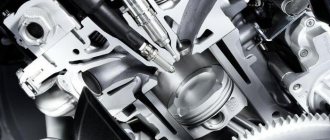
Functions of the crankshaft pulley
A crankshaft pulley is one of the parts of the crankshaft of a car engine, which is attached to the front output (protruding beyond the engine crankcase) part of the shaft (toe) and with the help of a special toothed belt (in some engines - a chain) synchronizes the operation of the crankshaft and camshaft of the engine. In addition, the crankshaft pulley, through the timing belt, also transmits torque (in fact, provides energy) to a number of devices of the so-called “attachments” of the car engine:
- generator
- engine coolant pump
- power steering pump
- air conditioner
The crankshaft pulley also performs (along with the flywheel and balancers) the functions of damping vibrations and shocks of the crankshaft. During the production process of pulleys, they all undergo special balancing. As you can see, a number of important vehicle mechanisms, including the engine itself, depend on the trouble-free operation of the crankshaft pulley. If there is no strictly synchronous operation of the crankshaft and camshaft, the engine will not operate normally.
That is why every car owner is faced with the requirement to regularly replace the crankshaft pulley complete with the timing belt (and, as a rule, the coolant pump roller). For each car model, there is a certain frequency for replacing the crankshaft pulley and timing belt. Wear and stretching of the timing belts, wear of the crankshaft pulley or pump roller can lead to engine malfunction, and in the worst case, to a break in the timing belt with subsequent damage to the entire crank group of the engine. Therefore, regular maintenance and replacement of the timing belt and crankshaft pulley should be taken seriously.
Conditions for generating DTC P0420
The ECM, in the process of monitoring, compares the signals of the 1st and 2nd sensors during a given time interval, calculating the duration of the voltage signal, and if it goes beyond a given threshold, the “brain” of the car interprets this as a malfunction of the neutralizer. The threshold value of the difference between the amplitudes of the front S1 (taken as the standard) and rear S2 oxygen sensors is more than 0.7 times per minute. But the check light, indicating that an error has been recorded in the memory of the ECM unit, does not light up instantly, but only when a decrease in the performance characteristics of the catalytic converter occurs for 100 seconds, and the engine load should be from 21 to 63% when the crankshaft rotates 1,720 - 2,800 rpm, and the catalyst temperature exceeds 500 degrees.
Signal from oxygen sensor
During normal operation of the catalytic converter, the downstream heated oxygen sensor signal switches slowly between rich and lean conditions. Frequent switching of the lambda probe between these states indicates a decrease in the efficiency of the converter. As a result, its ability to accumulate oxygen is reduced.
The task of the catalyst is to oxidize carbon monoxide and neutralize CO2 hydrocarbon emissions in order to reduce the concentration of harmful substances. This process, starting with the Euro 3 standard, is monitored by two oxygen sensors. There is a constant comparison of the signals of the first and second lambda in order to register the convergence of their readings. Therefore, error code P0420, in due time, will bother all owners of cars, including VAZ, Nissan, Toyota, Chevrolet, Ford, Honda or others produced after 1996 and having 2 lambda probes in the exhaust system.
Trouble code P0420 appears when oxygen and unburnt fuel residues are detected in the exhaust gases.
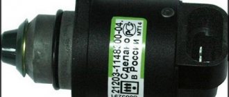
Damper adjustment
In order for the throttle valve to work like a clock, its sensor must be periodically adjusted. To do this, follow a few simple steps:
- The ignition is turned off to move the valve to the closed position.
- The sensor connector is de-energized.
- The sensor is adjusted using a 0.4 mm probe located between the screw and the lever.
To check the serviceability of the sensor, the voltage level is measured using an ohmmeter. If voltage is detected, the sensor should be replaced. In the opposite situation, you can continue to adjust the sensor.
To do this, the damper rotates until you see the same indicators that are written in the car's passport. Do not forget to check the tightness of the screws and nuts after adjustment; they could have become loose during the process.
As you know, the fuel system of a car is its vitality. If it is even slightly damaged, the car may unpleasantly surprise you at the most inopportune moment. If the throttle valve or another element of the assembly fails, the consequences can be disastrous. Therefore, it is much better not to skimp on car diagnostics if there is the slightest suspicion of a malfunction. Remember - safety on the road comes first.
Decoding errors
Each code consists of five characters: P 1 4. Let's say right away about the fourth and fifth characters - they indicate the serial number of the error. Now it’s worth taking a closer look at what the codes consist of
The first character may vary depending on the vehicle system:
- P – malfunctions in the operation of the power plant; the symbol also indicates defects in the automatic transmission.
- U – you need to look for a fault in the interaction node between the system units.
- B – defects in the operation of body systems, which include electric lifts, airbags, etc.
- C – chassis sensors have detected a malfunction in the chassis system.
Let's move on to the second character:
- 3 – reserve.
- 2 and 1 – codes set by the manufacturer.
- – common code for on-board diagnostics (OBD-II).
Low throttle position
Let's go back to cleaning the throttle body and set the record straight.
We often see this kind of rating of clean dampers.
People are really happy when, after cleaning (or not cleaning) the throttle valve, the readings of the throttle valve position are less than those of the loser who didn’t clean it well. He got 2.5%, but I got as much as 0.8%! Simply cool!
Should we be happy about such a low throttle position?
Again, not to be unfounded, let's conduct an experiment.
Let's take as a basis our well-known fact that for certain engine operating parameters a certain mass of air is required.
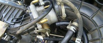
We connect the adapter for car diagnostics and start the engine at idle speed. We look at the parameter “DZ position”
The throttle position (opening) is 2.4%. The position of the idle air control (STEP) is 24
Disconnect any hose from the intake manifold. For example, a short hose from the crankcase ventilation system valve
This will ensure that excess air is sucked into the intake manifold.
Now let's look at the throttle position readings
The value of the remote sensing position became 0.8%! What a cool way to clean the throttle valve without even getting your hands dirty
And the position of the IAC became only 5 steps.
Is it clear what happened?
The mass of air entering through the disconnected hose is almost enough to keep the engine idling, so to prevent the speed from increasing above the required speed, the ECU closed the throttle valve.
Therefore, you should not rejoice at small throttle position values on cars with idle speed control using remote control!
There are two main reasons for low throttle position on Lacetti 1.4/1.6 and similar cars:
- Air leak into the intake manifold. This also reduces the idle speed control steps.
- The cable from the gas pedal to the throttle valve is not adjusted correctly. In this case, the idle speed control steps do not decrease, but remain normal.
I talk about this in more detail in the video at the end of this article. Be sure to watch it if your car has a low DS position.
Adaptive box - how does it work?
There is a difference between an adaptive and a simple machine. A simple automatic transmission does not remember the driver’s driving style; it simply shifts gears at 2500 rpm and only on kickdown spins the engine to the maximum permissible speed. The adaptive box is based on many parameters:
- Overclocking The box remembers how the driver accelerates and gradually makes the fast start smooth and without jerking.
- Driving style. The automatic transmission itself will protect against excessive fuel consumption and will take into account the driver’s desire to constantly press the gas pedal.
- Braking style. Ultimately, the box also remembers the braking features. Quick stops will teach the box to drop 2-3 gears at once without the driver noticing.
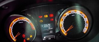
How is self-diagnosis performed?
We have sorted out the main errors on the Priora, now it’s worth finding out how self-diagnosis is performed. The VAZ 2170 with 16 valves has a special controller with which diagnostics are performed. If you have an on-board computer installed, then diagnostics are performed on it. There is also special equipment that allows for a more in-depth check of Priora 16 class systems.
Since most Priora 16 cars already have an on-board computer, we will consider the option without the use of special devices. Diagnostics begins with activation of the test mode. The work proceeds according to the following scheme:
- Turn off the ignition. Now we hold down the daily mileage reset button, without releasing the button, we start the ignition of the Priora 16 cl;
- On the instrument panel you will see a display with an indication. After turning on the ignition, all components of the instrument panel will light up. The needles of the temperature, speedometer, tachometer and other instruments will begin to move to the maximum level and back. This behavior indicates that self-diagnosis has begun;
- Let's move on to the right steering wheel switch. Here you will find a button for switching the on-board computer settings. Click on it, a message with the software version will appear on the instrument panel screen;
- The instrument panel error diagnosis will begin if you press this key again. Various codes will appear on the display, which you can decipher in the table below;
- When the diagnostics are complete, you can reset the error data. Press and hold the daily mileage reset button for about 5 seconds.
Tips to Avoid P0101 in the Future
Dirt and carbon deposits in the engine can cause many problems, including trouble code P0101. Check the air filter regularly and make sure it is installed correctly when replacing it. Regular maintenance of your engine fluids, especially oil, will also help keep your engine clean.
This code can also be caused by worn wire insulation. Make sure all wires are kept away from ignition coils and other potential sources of damage.
Test methods and problem solving
In some cases, it is necessary to check the serviceability of the oxygen sensor or the exhaust system and manifold for leaks. Leaks and leaks can affect the operation of the O2 sensors and cause the P0420 error code to appear, but still, more often this problem is directly related only to the condition of the catalyst.
Some tips for a troubleshooting plan
Before starting diagnostics, in order to save time on finding out the cause and fixing the problem, we advise you to carry out a few simple checks, and then proceed to further, complex solutions to the problem. So:
- First of all, remember what gas station you refueled at and whether you filled it with fuel, as always. And also make sure that there are no symptoms of coolant getting into the engine, as well as oil consumption.
- Check the ignition timing . Reducing the ignition timing below the required angle can increase the temperature of the exhaust gases and, over time, reduce the efficiency of the catalyst.
- Check the connector of the 2nd (“rear”) sensor . Having made sure that all this was unchanged, you will have to connect a computer to retrieve data from the electronic control unit.
Checking the operation of the catalytic converter and its parameters
To assess the efficiency of the catalyst, it is necessary to compare the output voltage graphs between the “upper” and “lower” oxygen sensors, as well as look at the fuel supply adjustment data.
Oxygen sensor readings on an oscilloscope
The output voltage of the oxygen sensor, read by the car's computer, will decrease when the mixture is lean and increase when it is rich. A normal reading for an oxygen sensor will fluctuate between 900 millivolts (rich condition) and 100 millivolts (lean condition).
Short-term adjustment, ideally, should tend to “0”, but on an engine with mileage, deviations from the norm of up to 10% are acceptable. And when the fuel adjustment exceeds 25%, then a long-term adjustment also occurs, so if both values are present, this indicates a problem in preparing the fuel-air mixture. Therefore, pay attention to the presence of additional fault codes.
Theory and mechanisms of damping in structural mechanics
If you hit a glass or metal bowl, it will emit a ringing sound that fades over time. In a world without damping, this ringing would continue forever. In reality, through several physical processes, the kinetic energy and (potential) elastic energy of the bowl are converted into other forms of energy. In this article, we will discuss how to describe damping in models and what physical phenomena cause damping in vibrating mechanical systems.
How is damping described mathematically?
There are several mathematical approaches to describing and accounting for damping. Let's briefly summarize the most popular ones.
The most noticeable manifestation of damping is the decrease (attenuation) of the amplitude of free vibrations over time, as, for example, in the case of a “singing” bowl. The rate at which the amplitude decays depends on how much damping is in the system. Typically, the amplitude of the oscillations decays exponentially with time. In this case, the energy loss over a period is proportional to the amplitude of the oscillations (over this period).
Classic "singing" bowl. Image courtesy of Sneharamm0han - own creation. Available under CC BY-SA 4.0 license from Wikimedia Commons.
Let's start with the equation of motion for a one-degree-of-freedom system with viscous friction in the absence of external loads.
Dividing by the mass m, we obtain a normalized equation, which is usually written as
Here omega_0 is the natural frequency of undamped vibrations, and zeta is the relative damping ratio.
For the motion to be periodic, the relative damping coefficient must remain in the range 0 le zeta. The amplitude of free oscillations in this system will fall in proportion to the factor
where T is the period of oscillation without damping.
Damping of free vibrations with three different relative damping ratios.
In this context, there is another frequently used criterion - the logarithmic decrement δ. This is the logarithm of the ratio of amplitudes in two consecutive periods:
The relationship between logarithmic decrement and relative damping ratio is as follows:
Another case where the damping effect plays a key role is the excitation of harmonic vibrations in a structure at a frequency close to the natural frequency of the system. At precise resonance, the oscillation amplitude will tend to infinity until damping is taken into account. The actual amplitude at resonance is actually determined by the amount of such damping.
Frequency (resonant) response of a system with one degree of freedom at different relative damping ratios.
In systems such as resonators, we want to achieve as much gain as possible. Related to this is another criterion that describes damping - quality factor (Q-factor). Quality factor can be defined as the gain at resonance. It is related to the relative damping coefficient:
Another formalism for the mathematical description of damping is based on the assumption that there is some kind of phase shift between the applied force and the resulting displacement, or, in other words, between stress and strain. Discussion of such phase shifts is appropriate only in the case of steady-state harmonic oscillations. If you plot the stress versus strain for a full period, you will see an ellipse - a hysteresis loop.
Loading curve.
In this version, it is possible to represent the properties of a material as complex-valued quantities. For uniaxial linear elastic deformation, the complex relationship between stress and strain can be written as
The real part of the Young's modulus in this relation is called the storage modulus, and the imaginary part is called the loss modulus. The loss modulus is usually described through the hysteresis loss factor (loss factor) η, namely:
In this expression, E coincides with the storage modulus E'. You can also find another definition in which E denotes the relationship between the stress amplitude and the strain amplitude, that is
This difference is important only for large values of the hysteresis loss coefficient. An equivalent metric is the loss tangent, namely
The loss angle δ determines the phase shift between stress and strain.
Damping, specified through the hysteresis loss coefficient, is somewhat different from the case of viscous damping. Hysteresis losses are proportional to the amplitude of the displacements, and viscous damping is proportional to the speed. Thus, these quantities cannot be unambiguously related to each other.
The figure below compares the response of a single degree of freedom system using two different damping models. It can be seen that the viscous damping model predicts stronger damping at frequencies above resonant compared to the model through the hysteresis loss coefficient and weaker damping at frequencies below resonant.
Comparison of the dynamic response for the viscous damping model (solid lines) and for the model through the hysteresis loss coefficient (dashed lines).
Typically, at the resonant frequency, the following relationship between the specified criteria is satisfied: eta approx 2 zeta. But this relationship holds only at one frequency. The figure below shows a system with two degrees of freedom. The values of the coefficients were selected for the first resonance, and it is clearly visible that the curves for the second resonance diverge quite seriously.
Comparison of the dynamic response for the viscous damping model (solid lines) and for the model through the hysteresis loss coefficient (dashed lines) in a system with two degrees of freedom.
The concept of hysteresis loss factor can be generalized by defining it in terms of energy. It can be shown that in the material model described above, the energy dissipated in one period is
where varepsilon_a is the deformation amplitude.
Similarly, the maximum energy of elastic deformation per period is equal to
The hysteresis loss coefficient can then be written in terms of energy quantities:
This definition in terms of dissipated energy can be used even if the hysteresis loop does not look like a perfect ellipse; it is enough just to be able to determine these two energy quantities.
Damping sources
There are a huge variety of physical damping mechanisms. In all natural processes, energy is dissipated in one way or another.
Internal losses in the material
In all real materials, energy is dissipated during deformation. This can be considered a type of internal friction. Note that the loading curve for a full period does not fit on a perfectly straight line. It looks more like an elongated ellipse.
Usually, to describe damping in a material, a model is used in terms of the hysteresis loss coefficient, since experimentally it turns out that energy losses over a period weakly depend on frequency and amplitude. In this case, the mathematical description in the loss coefficient model is based on complex values, that is, it implies only the case of harmonic oscillations. Therefore, this damping model can only be used for frequency domain studies.
Common Causes of Code P0420
With proper operation, the service life of the catalyst is at least 200-250 thousand km, but if you regularly refuel with fuel that contains impurities with a high concentration of lead, its destruction will be accelerated. Also, due to poor fuel or faulty ignition and gas distribution, compression is disrupted and misfires occur, which directly contributes to both a decrease in the service life of the catalytic converter and, in fact, the appearance of an error code P0420 or P0430.
So, the main possible reasons:
- Leaded gasoline is used.
- The S2 oxygen sensor is damaged or faulty.
- Short circuit in the “lower” oxygen sensor circuit.
- Damage to the catalyst.
- Damage to the exhaust system (exhaust manifold, muffler, pipes, gaskets, etc.).
- Prolonged operation of the vehicle with misfires in the cylinders.
- Increased fuel pressure in the system.
As you can see, there may be at least 7 reasons why error P0420 pops up , although often everything is much simpler, and drivers are faced with the need to cut out or change the catalyst by installing a lambda snag. And for the luckiest ones, when this malfunction appears at a not so high mileage, it is enough to refuel with good gasoline or check the contacts of the lambda sensor.
3 main reasons why error P0420 appears and how to fix it.
To correctly determine the malfunction that caused this code to appear, it is necessary to thoroughly diagnose all possible causes.
Mass shock absorbers in cars
Motorsport
A tuned mass damper was introduced as part of the suspension system by Renault on its 2005 F1 car (Renault R25) at the 2005 Brazilian Grand Prix. The system was invented by Dr. Robin Tului, and it reportedly reduced lap times by 0.3 seconds: a phenomenal gain for a relatively simple device. The stewards of the meeting considered this to be legal, but the FIA appealed the decision.
Two weeks later, the FIA International Court of Appeal ruled the mass damper illegal. This was ruled illegal because the mass was not rigidly fixed to the frame and because of the effect it had on the pitch of the car, which in turn significantly affected the gap under the car and therefore the ground effects of the car, which is a movable aerodynamic device and therefore unlawfully affecting aerodynamic performance.
Production cars
Tuned mass shock absorbers are widely used in production vehicles, typically on the crankshaft pulley to control torsional vibration and, less commonly, flex modes of the crankshaft. They are also used in drivetrains for baloney and elsewhere to eliminate other noise or vibration in the exhaust, body, suspension or anywhere else. Almost all modern cars will have one mass damper, and some may have ten or more.
A typical crankshaft damper design consists of a thin rubber between the pulley hub and the outer rim. This device, often called a harmonic damper, is located on the other end of the crankshaft, opposite the flywheel and transmission. An alternative design is the centrifugal pendulum shock absorber, which is used to reduce torsional vibration of the internal combustion engine in some modern vehicles.
All four wheels of the Citroën 2CV included a tuned mass damper (called "Batteur" in the original French) of a very similar design to that used in the Renault F1 car, from the start of production in 1949 on all four wheels. before it was dropped from the rear and finally the front wheels in the mid-1970s.
Tips for setting up a subwoofer
- Haste and proper setup of the speaker system are incompatible things. You should set aside several hours of free time for high-quality setup.
- It is best to check the sound on known or favorite tracks, where you can definitely distinguish the correct sound from the distorted one.
- To check the tracks, you should listen to them with the doors and windows closed in the driver's seat, this way you can catch the slightest defects.
- Do not limit yourself to checking on one track; it would be best to carefully listen to several compositions of different genres and with a different set of sound frequencies.
- There are no specific parameters to which filter metrics need to be set. This article provides only the optimal and most popular parameter settings. It is necessary to configure based on personal taste preferences, monitoring the harmonious sound of the front midbass and subwoofer head.
By adjusting all the filters in this manner, you can achieve a loud subwoofer sound, while it will work harmoniously, without blocking the overall musical tone. This setting is suitable for all musical genres and will help expand the range of their sound.
vote
Article rating