Repairing the cylinder head (cylinder head) is a necessary measure associated with a malfunction of the internal combustion engine. Symptoms of malfunction:
- Smokes
- Eats oil
- Doesn't start on first crank with starter
- The engine won't start
- Due to valve breakage
Repair of the cylinder head is carried out after accurately establishing the cause of the malfunction, which can be determined by diagnostic methods, both on the carburetor engine and on the injector.
On a car, the same malfunction can be caused by different reasons. For example, if the engine begins to run intermittently or is tripping, this does not mean that the culprit of the malfunction is the cylinder head. Repair is an expensive operation and therefore first of all it is necessary to determine:
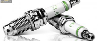
- whether the spark plugs, high-voltage wires and ignition coil work correctly;
- serviceability of fuel injectors;
- presence of a switching signal at the connectors of the injectors and ignition coil;
- whether the fuel pump provides the required fuel pressure in the rail.
If there are no malfunctions in the injection engine control system, you can begin to repair the cylinder head.
Next, let's look at the example of the 8-valve engine of the VAZ family of cars: 2108, 2109, 2110, 2111, 2113, 2114, 2115, Granta, Kalina, Priora, and the basics of repairing the cylinder head.
Replacing Valve Guides
Critical depletion of guide bushings occurs at a mileage of 150-200 thousand km. You can do the cylinder head repair by replacing the bushings yourself. To replace them you will have to dry out all the valves. Then, using a mandrel to knock out the bushings, remove them from the head body.
It will be a little more difficult to install the new bushings in place. For correct and easy installation, you should use a temperature imbalance - heat the block head (this expands the metal, and therefore the bushing seat), and cool the new bushings to a negative temperature. The head body in the right place should be heated to 100 degrees.
This can be done using an electric stove, placing the cylinder head on it so that the work site is in the zone of maximum heating. Having lubricated the new bushings (cooled in the freezer of a regular refrigerator) with machine oil, we drive them into the mounting sockets. If you follow the recommendations for temperature preparation described above, the bushings will fit in easily, like clockwork.
After the metal has cooled, the bushings must be expanded to a diameter that allows the valve to move without jamming or distortion. In this case, the work must be done so that the valve stem does not dangle. To perform this procedure, you need a special tool - a reamer. The peculiarity is that they need to work only on one side, turning the reamer to the end. A big mistake is to bore the guide bushing on both sides - you will end up having to change the bushing again.
Remember that cylinder head repair is a complex process, the slightest inaccuracy of which can result in wasted nerves and money. As a rule, an oversight makes itself felt after assembling and starting the engine. This does not always happen immediately, but certainly within the first thousand kilometers.
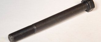
Hardened bolts or cylinder head bolts 2101
Hardened cylinder head bolts for Niva and classics, old model Niva cylinder head bolts are divided into two groups. Hardened and plastically deformable. I will talk in detail about the second type in the second part. Now we are talking about hardened bolts. Part number 2101-1003271. The number shows that the pedigree of these bolts dates back to the “kopeck”, and to be more honest, from the Fiat. Strength 10.9, this is clearly stamped on the head of the bolt. But for modern requirements, this is not enough. The fundamental difference from deformable cylinder head bolts is that they DO NOT STRETCH. This is their plus and minus. The advantage is that they are reusable. The downside is that if the cylinder head gasket is shrinkage, then after installation, after a short mileage, it is advisable to “stretch” it. For a very long time I worked myself and completed orders with these bolts. But when AvtoTAZ again “sagged” in the quality of cylinder head processing and even shrink gaskets came from the factory again instead of the modern “metal package”, it switched to deformable bolts, which are suitable for both options.
Countersinking saddles
When repairing the cylinder head yourself, be prepared for the most monotonous and lengthy process - countersinking. A lot depends on its quality:
- tight fit of the valve to the seat;
- compression ratio in the combustion chamber.
The seat grinding work is carried out with a special tool - a roller cutter (less often - a countersink). With its help, a not quite finished seat can be given the desired shape so that the valve fits more tightly. Start work with a countersink at 60 degrees.
As soon as metal removal has begun in a circle, change the nozzle - take a countersink with a cone angle of 120 degrees. Work with it until a clear round edge appears. The final stage of countersinking is done with a 90-degree cone - it should go through the working chamfer of no more than 1.5 mm. Further grinding of the valve will increase it to the required value.
Grinding in the valves
After preparing the seat, the next stage of repair awaits us - grinding in the valves. To do this you will need a special lapping paste. A small layer is applied to the valve, then the latter is inserted into the head. A piece of rubber hose (of such a diameter that it is difficult to fit) is placed on the valve stem.
Then place the free end between your palms and begin, rubbing your hands, to rotate the valve in different directions. The abrasive paste will do its job, and the repair of the cylinder head valve can be considered complete.
Head milling
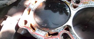
There are several cylinder head malfunctions that you cannot fix on your own. When the engine overheats systematically, the aluminum cylinder head becomes deformed. The perfectly flat surface of contact between the head and the engine block ceases to be so.
This leads to the gasket between the block and the head starting to leak. Replacing it with a new one does not solve the problem. In this case, grinding the adjacent surface may be the solution. Milling is performed on a special machine, which allows the work to be completed with perfect precision.
In the conditions of your garage, it is unlikely to carry out such a procedure yourself. Using a hand sander (as some garage “kulibins” advise) for this purpose means completely ruining the adjacent surface. In this case, repairing the cylinder head will lead to a complete replacement of the head - it is impossible to grind it indefinitely.
Cracks
If overheated, the housing may also rupture in the form of cracks. They are not always visible to the eye, but their presence greatly affects the proper operation of the engine. If cracks have formed in the areas where the head and block meet, or in the valve seats, you will have no choice but to replace the block head with a new one. All other areas can be restored using argon welding. It is impossible to do such a cylinder head repair yourself due to the lack of specialized equipment - not all service stations have such welding.
As you can see, not everything can be repaired on your own. By correctly assessing the scope of work, you will nevertheless be able to save money on your budget.
Video on the topic:
Hello people, tell me which head to unscrew the cylinder head bolts with, I don’t have a hex head, but some kind of sprockets. There are no such people at home or at work to take and not make a mistake. Does the marking seem to be E12, E14 or E16? VAZ 2109, injector. What is the key for the cylinder head.
Similar articles
17 comments on “What is the key for the cylinder head. Which head should I use to unscrew the cylinder head bolts?
With a regular 13mm head you can unscrew it
Andrey, I tried the head on 13, it just scrolls, on 12 it does the same, and on 11 it fits exactly. Only the bolt head is made in the form of an asterisk, and I am not sure that a regular 11 head is the key that is needed to unscrew these bolts.
Cylinder head repair
Warning! The cylinder head is replaced with the bearing housings assemblies, since they are processed together.
You will need: keys “13”, “17”, “21”, a spark plug wrench, a screwdriver, pliers (tweezers), a device for compressing valve springs.
2. Unscrew the two fastening nuts and remove the eye.
3. Unscrew the fastening nut one or two turns and remove the bracket for the water pump supply pipe.
4. Unscrew the screw securing the fuel pipe holder and remove the holder.
5. Unscrew the three nuts securing the receiver and the two nuts securing the bracket for the fuel pipes.
6. Remove the fuel pipe bracket.
7. Unscrew the remaining two receiver mounting nuts.
8. Loosen the nut securing the receiver bracket.
9. Remove the receiver.
10. Unscrew the three nuts securing the receiver bracket and remove the bracket.
11. Unscrew the four nuts securing the inlet pipe.
12. Remove the inlet pipe.
13. Unscrew the two nuts securing the exhaust manifold and remove the manifold.
14. Carefully remove the two gaskets from the intake pipe and exhaust manifold.
Helpful advice. Even if the gaskets are not damaged and are slightly compressed, it is better to replace them and not reuse them.
Assembly Features
Before assembly, you should check the bolts securing the head to the hood; their length should not be more than 13.5 cm; if they are longer, they can no longer be used.
You should also check the flatness of the head. If it was overheated, it is possible that it was warped and will require repair in the form of trimming the plane.
During assembly, the head bolts are tightened in a certain sequence and with a strictly defined tightening torque. Next, everything is assembled in the reverse order of disassembly.
Disassembly is also carried out in the same sequence if the power plant is being modified.
Conversion kit for an 8-valve injection engine to a 16-valve engine. You can check prices here www.tltzap.ru/price.html#1
The kit includes: price: 1. Cylinder head 21126 assembled.___________________17,000 2. Timing casing.___________________________1000 3. Timing rollers___________________________500 4. Timing belt 2112______________________________250 5. Water pump 2112________________550-1000 6. Bare fuel rail with tube 7. Injector wiring 8. Pistons 21124 82.0____________________1000 9. Piston pins 2110______________50-75 10. Retaining rings_____________1-25 for 1 piece 11. Modified cylinder head bolts 2108___________40 for 1 piece 12. Intake receiver____________________4500 13. Exhaust manifold gasket_______2-36 for 1 piece 14. Exhaust manifold (spider 4 -2-1)_______1800 15. Modified cylinder head gasket__________ 16. Oil dipstick________________________75 17. Aluminum breather____________780 18. Lower breather hose (thick) 2112_____30 19. Damper 2112_______________________550 20. Crankshaft pulley 2112____________870 2 1. Valve cover 21126______________1400 22. Timing pulleys__________________________950 23. Coils ignition 24. Ignition coil wiring 25. Spark plugs 2112 26. Crankshaft bolt 27. Camshaft bolts 28 Camshaft bolt washers 29. Valve cover bolts 30. Timing roller nuts 31. Timing roller washers 32. 4mm alignment washers for the rollers. 33. Timing cover mounting bolts. PS: Pistons can be replaced with sizes 82.4 and 82.8.__770-2950 per set
When to replace the cylinder head
The cylinder head is a fairly durable working unit, so it is not subject to repair or complete replacement very often. On cars manufactured in the Russian Federation, the cylinder head has to be removed due to cylinder leakage or when the gasket is worn out.
And sometimes the cylinder head is removed for modification. Removing this unit on a car with any number of valves is quite easy, although some skill may be required.
In this regard, if you need to remove the cylinder head yourself for the first time, then it is best to do this under the supervision of a person who has previously encountered a similar task.
Work process
- Disconnect the negative terminals from the battery.
- The piston of the first cylinder is set to the top dead center position.
- All coolant is drained.
- Fuel pressure decreases.
- The intake pipe of the exhaust system is disconnected from the manifold.
- The cylinder head cover is being dismantled.
- All pipes, electrical wires and hoses are removed. But before you do this, you need to remember or note what was originally connected and where. This is done in order to avoid possible confusion during re-installation.
- There are three bolts on the camshaft belt cover that need to be unscrewed and the cover itself removed.
- The timing belt is removed and completely removed.
- The shafts must be secured against possible rotation.
- The pulley is attached to the camshaft using bolts that must be unscrewed and then the pulley removed.
- The nut securing the rear camshaft cover is unscrewed.
- Unscrew the remaining bolts and remove the cover completely.
- Slightly loosen the tension of the dozen bolts holding the head.
- Then each individual bolt is unscrewed one by one and removed along with the washers.
- The head is released and removed.
- If the head is attached directly to the gasket, a screwdriver or any other long tool should be inserted under the manifold. Next, you need to use this tool as a lever in order to slightly lift the head, and then remove it completely.
- Very carefully, so as not to scratch the surface of the head, it is necessary to remove the remnants of the old gasket. It is best to use a special liquid for this matter.
- We put the new gasket in place.
- We make sure that the shafts are in the top dead center position and all valves on the first cylinder are completely closed.
- We put the bolts back.
- Using a torque wrench, we begin to tighten the bolts one by one.
- We reinstall all removed equipment.
- We adjust the clearances in the valve drive and tension the camshaft belt.
As you can see, repairing the cylinder head on a VAZ-2114, which has 8 valves, is a fairly simple, albeit slightly labor-intensive task, which means that every person who has at least a slight understanding of this unit can handle it.
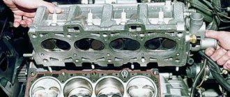
Cylinder head repair process
Dismantling
On cars with 8 cl engines, the cylinder heads are the same type and interchangeable. Accordingly, all mechanics of actions are carried out regardless of the car model using a single repair technology. When starting to dismantle the cylinder head, general preparation of the vehicle and tools is carried out. The first necessary action is to disconnect the on-board electrical network from the battery. To do this, simply remove the negative terminal from the battery. The second action is aimed at carrying out work related to draining the coolant from the cylinder block by unscrewing the plug located between the third and fourth cylinders. There is no need to drain the fluid from the radiator.
Remove the air filter housing with the rubber pipe by unscrewing the clamp on the throttle assembly. Disconnect the fuel lines from the injector rail.
Disconnect the throttle control cable from the throttle assembly.
Unscrew the two valve cover nuts and remove it. The valve cover gasket must be replaced with a new one during assembly.
After carrying out the general preparatory work, we proceed directly to disassembling the parts and assemblies that prevent the final lifting of the head from the cylinder block.
Unscrew the three bolts of the timing belt mechanism protective cover and remove the cover.
Set the piston of the first cylinder to the top dead center position, while the mark on the camshaft gear should be located opposite the bent bracket of the cover housing.
Fix the position of the crankshaft with a special comb through the inspection hole on the flywheel housing.
Unscrew the nut holding the timing belt tensioner pulley and remove it with a set of washers.
Remove the belt from the camshaft gear and pump and move it to the side.
While holding the camshaft, unscrew the bolt from the gear and remove it.
Unscrew the bolts securing the reflector to the cylinder head housing and cylinder block and remove it together with the pump.
Next, you need to unscrew the two nuts and bolt from the side camshaft cover and remove it, as well as remove the thermostat housing, which is mounted on studs.
Unscrew the nuts securing the upper camshaft bed covers. Remove the covers and camshaft.
Unscrew all the nuts securing the exhaust and intake manifolds and separate them from the head towards the windshield.
The cylinder head mounting bolts are most often made with a Torx key (Torx External). The head of such a bolt has the shape of a six-pointed star and its use is based on the purpose of reducing its size.
Depressurization of valves
Structurally, in the cylinder head, the valve stem passes through a guide pressed into the body of the head. The operation of the valve mechanism is ensured by sequentially assembled parts: lower spring seat, valve stem seal, external spring, internal spring, upper cone seat, retaining nuts.
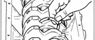
For further work related to replacing the valve or seat, pressing out the guide bushing, the unit must be disassembled. It is not difficult to carry out the disassembly operation if you have a “dehumidifier” device, which is a system of levers. The end point of the lever is attached to the supporting surface, and the middle part rests with a ring on the upper spring seat. By applying pressure on the spring seat with a lever, access to cone-shaped crackers is opened, which are removed with tweezers.
If you perform desiccation with your own hands and do not have a device, this action can be performed with a hammer blow, having previously selected the mandrel to the size of the upper spring seat.
Replacing guides
Valve guides must be replaced if the permissible runout is exceeded, which is no more than 0.6 mm for exhaust valves, and no more than 0.4 mm for intake valves.
The runout is checked using special equipment consisting of a massive plate, which is mounted on the head surface that has already been prepared on a milling machine. A tripod allows you to hold the micrometer in the desired position by moving it vertically and horizontally. Having deflected the valve, inserted into the guide in the direction of movement of the rod until it stops, bring the working head of the micrometer until it touches the valve plate. The arrow on the micrometer is set to zero by rotating the scale and the valve is deflected towards the movement of the micrometer rod. The arrow readings should not exceed 40 divisions for the inlet valve and 60 divisions for the exhaust valve.
If the permissible standards are exceeded, the guide is pressed out with a special drift and a new one is pressed in as well. Then it is processed with sweeps.
It should be borne in mind that the guide for the exhaust valve on the inner surface has a heat-dissipating thread along its entire length, and the intake valve only up to half the length.
Countersink
When installing a new valve guide, the centerline of the valve guide will in most cases not be aligned with the center axis of the seat. To restore the alignment and tight fit of the valve plate to the seat, its edges are processed with special cutters that have three chamfer angles:
- upper correction angle – 300
- valve seat angle - 450
- lower correction angle - 600
A set of cutters for countersinking intake and exhaust valves and mandrels for them can be purchased at specialized retail chains.
Lapping
Lapping of the seat-valve pair is performed to obtain a tight seal. Lapping is carried out using a drill, a manual collet lever equipped with a return spring, or a pneumatic device with a set of suction cups of different sizes. A composition of grinding powder and motor oil is used as an abrasive, or ready-made lapping pastes are used.
Before grinding, you need to lubricate the valve stem with oil and install the valve in the guide. Then prepare the device and, lifting the valve plate above the seat, place lapping paste along the edge of the plate.
By performing rotational movements around the valve axis in combination with reciprocating movements, the valve is ground into the seat. The appearance of a matte gray belt on the seat chamfer indicates the quality of the surfaces being ground.
Leak test
Upon completion of the grinding operation, finally check the quality of the seal with kerosene with the valves closed. If a kerosene leak is not detected after holding for 2-3 hours, then the cylinder head can be finally assembled. If a leak is detected, the grinding operation should be repeated.
Replacing valve stem seals
Replacement of valve stem seals is mandatory when repairing the cylinder head. During engine operation, options are possible when a defective oil seal (oil seal) flies off the top of the valve guide and moves freely along its rod. A symptom of a malfunction associated with the valve stem seal is the appearance of smoke from the muffler during re-gassing and a slight drop in the oil level in the crankcase. If a malfunction occurs during engine operation, the valve stem seals can be replaced without removing the cylinder head from the engine. It is enough to disassemble the valve cover and remove the camshaft.
Dry out the valve assembly, remove the springs and remove the damaged caps with a special tool (puller pliers, impact collet).
Lubricate the new caps with oil and press them lightly with a hammer through a special mandrel onto the upper part of the guide.
Reassemble the valve assembly and camshaft in reverse order and adjust the valve clearances.
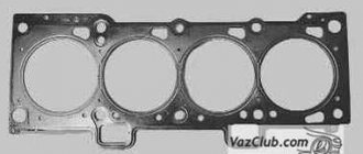
Replacing the cylinder head gasket
During repairs or in case of damage to the cylinder head gasket, it is necessary to remove the head from the engine. The working part of the surface must be leveled by grinding (this is done more efficiently on a milling machine). Clean the mating surface of the cylinder block from traces of the old gasket, blow air to remove particles and dust, as well as the threaded wells for the bolts securing the head.
Place a new gasket on the surface of the cylinder block and perform installation in the reverse order.
VAZ cylinder head assembly
Assembling the cylinder head must begin after thoroughly purging the surface from foreign objects and particles. Pay special attention to the cleanliness of the internal surfaces of the valve guides and oil supply channels on the camshaft beds. Lubricate the camshaft seats and oil seal, valve stems, tappets and valve stem seals with engine oil.
Insert the valves into the guides (each valve, after grinding in, strictly belongs to the corresponding cylinder). Orient the cylinder head on the table for assembling the valve assemblies and place the lower spring washers. Using a special impact mandrel, press in the valve stem seals and continue assembling the outer and inner springs. Place the upper conical washers on the springs and install the crackers - clamps - with a special tool - a desiccant tool.
The next stage of assembly is the installation of pushers, which, like valves, are inserted in strict accordance with the corresponding cylinder. The final step in assembling the cylinder head is installing the camshaft. The camshaft along with the oil seal is placed on the bed and the covers are placed on top. A thin layer of sealant is first applied to the extreme points of contact with the cylinder head surface. The covers are tightened with nuts and the head is ready for installation on the engine.
Is camshaft seal needed? This is a question that novice motorists ask. Rubber parts, if they are of good quality, do not require additional use of sealant.
Mounting on cylinder block
Before installation, it is necessary to clean and blow with compressed air the surface of the cylinder block from foreign particles, dust, drops of oil and antifreeze.
Place the cylinder head gasket on the surface of the cylinder block and carefully install the head, monitoring its position along the fixing bushings.
Next, the head mounting bolts are installed and 4 stages of tightening are done with a torque wrench:
- 20 N*m.
- 85.7 N*m
- 90°
- 90°
Pulling scheme
The following stages of installation are performed according to the technological process diagram in the reverse order of disassembly described above.
Checking and repairing the cylinder head of VAZ 2114, VAZ 2115, VAZ 2113, Lada Samara 2
The cylinder head should be thoroughly cleaned of carbon deposits from the surfaces of the combustion chambers and exhaust valves. Also remove any remaining oil from the oil channels.
There are no chips or damage on the camshaft journals and supports and in the holes where the Lada Samara 2 valve lifters are located.
To be sure, check whether antifreeze is getting into the oil channels; to do this, you need to plug all the coolant circulation holes. Using sediment, under a pressure of 0.5 MPa, pump water into the coolant circulation jacket, and within 3 minutes there should be no hint of water leakage from the cooling jacket.
When checking the tightness of the cylinder head using compressed air, it is also necessary to plug all coolant circulation jackets with special plugs. Select a reservoir, heat the water in it from 60 to 80 degrees and immerse the head in the reservoir of water. After 5 minutes, pump air into the head using a pump. The air pressure should be in the range from 0.15 to 0.2 MPa. No bubbles should form on the surface of the water for 2 minutes.
Valve seats: I — new seat; II - saddle after repair; a — intake valve seat; b — exhaust valve seat
Grinding of seats is possible if small scratches or damage have formed on the chamfers.
The procedure for grinding seat chamfers.
– before starting milling, you need to insert the rod into the valve sleeve of the VAZ 2113, VAZ 2114, VAZ 2115. Different cutters are used for the exhaust and intake valve seats. First mill a 15° chamfer
– then mill a chamfer 20
– grind the chamfer 45°, observing the diameters of 34 and 30.5 millimeters. Grinding of chamfers is carried out using canonical circles.
Only after the grinding circuit is installed on the chamfer can the machine be turned on. After finishing grinding, rinse and blow off the chamfers with compressed air.
Malfunctions after cylinder head repair or gasket replacement
The car won't start
If the car does not start after replacing the gasket, it is necessary to check the presence of a spark on the spark plugs and the fuel pressure in the rail. Make sure that there is no air leak through the fitting on the receiver intended for the vacuum brake booster tube.
Engine troubles
Just as with a major overhaul of the head, replacing the cylinder head gasket involves removing the head and, accordingly, disconnecting the connectors from the sensors, removing high-voltage wires, tubes connected to the intake manifold (receiver) from the vacuum brake booster, adsorber, and fuel pressure regulator.
If the engine stalls after installing the cylinder head, it is necessary to check all electrical connections and the presence of air leaks, as well as the thermal clearances of the timing valves. Rehabilitation after valve replacement usually lasts for 500 km, but there may be cases when, after the first start, it is necessary to adjust the thermal clearances.
A malfunction associated with engine tripping after repair may also be temporary, since the spark plugs may be wet and after several starts, thanks to purging and calcination, the engine begins to run smoothly.
The engine smokes
After replacing the gasket, the engine smokes as the temperature increases. This situation is quite normal. The antifreeze is drained, during disassembly, engine oil gets onto the surface of the engine, and as the engine heats up, all these liquids evaporate, causing smoke.
Burns oil after valve replacement
The valve stem seals were replaced without removing the cylinder head. It is possible that the valve stem seals are defective or damaged during pressing with a faulty mandrel.
No compression after valve replacement
After replacing the valves, it is recommended to warm up the internal combustion engine and measure the compression. If low compression is detected in one or more cylinders, check and adjust the valve clearances. If there is no compression in all cylinders and it is zero, then it is necessary to remove the cylinder head in order to inspect the integrity of the gas distribution mechanism parts and, if necessary, carry out a comprehensive engine repair.
Tightening torque of the cylinder head VAZ 2114 8 valves: consider the subtleties of the process
From time to time, the cylinder head gasket may fail due to wear and tear of its material or burnout. The main signs that it is time to replace the gasket with a new one are the appearance of local leaks of oil and coolant at the point of contact between the cylinder head and the engine. Tightening torque of the cylinder head VAZ 2114 8 valves: consider the subtleties of the process.
It should be remembered that when replacing a gasket, not only the tightening torque of the VAZ 2114 cylinder head is important, but also the entire sequence of operations - after all, the replacement itself is a very important and serious procedure, errors during which can lead to engine malfunction.
Lada 2114 Chetyrnashechka ATMO › Logbook › Repair and modernization of the cylinder head
Good day. I’ll say right away that we did this work a long time ago, about a year ago. I registered here recently and then I didn’t even think about posting anything online. Therefore, I will post what photographs there were.
As you know, the standard four does not differ in any kind of dynamics... Everything is clamped, the intake receiver is of small volume, the channels in the cylinder head are small, the purging is very weak. So it was decided to add dynamics, since I like the car and buying a Priora, for example, is expensive. The goal was to make the 14ka drive at least as weak as the Priora.
The whole point of the modernization was to lighten all the torque elements of the cylinder head + install a sports shaft from Kolobok - aka
+ installation of a sports intake receiver PBK.
What was done: 1) The cylinder head was removed and the channels were bored out by 3 millimeters + the channels were polished 2) Lightweight T-shaped valves + bronze guides + lightweight plates were installed 3) A Nuzhdin 10/93 camshaft was installed, phase 282 degrees. 4) BOSH 107 injectors installed 5) Installation of PBK receiver 6) Increased throttle I had for a long time, it was 54 in diameter. 7) Reassembly. New oil scraper rings were installed 9) The pistons were cleaned of carbon deposits (no photo)
Nothing has been done to the engine “yet”, but I’m planning on doing it in the spring. I installed everything new so that the funds allowed. Since we did everything ourselves, naturally it took about 1 week, maybe a little more. During assembly, various problems arise, since many parts do not fit into place, I had to come up with something, but in general everything worked out. Setting up online firmware for January 7.2. Everything was done about 1 year ago. I would like to note that nothing has broken in a year, it still runs and there are no glitches. I'm happy with the improvements, but as usual it's not enough. It feels like a completely different car, about 110-115 hp. this is enough for such a light car to catch up with that same Priora and get away from it. If you have questions, write in the comments and we’ll try to answer! Thanks for the help from azelon and a few other guys, I couldn’t do it alone! Everything cost at least 15,000 rubles
Required Tools and Process
In order to do it correctly, you will need:
- set of socket heads;
- extension;
- ratchet/wrench;
- torque wrench.
The replacement process itself should be performed according to the following scheme:
- Disconnect the wires leading to the emergency oil level and coolant temperature sensors.
- Drain the coolant.
- Remove the thermostat.
- Remove the air filter housing.
- Disconnect the exhaust pipe inlet from the manifold.
- Remove the casing, as well as the camshaft belt itself.
- Disconnect the drive rods of both dampers from the carburetor.
- Disconnect the wires going to the cylinder head.
- Disconnect the hoses suitable for the cylinder head by loosening their clamps.
- Remove the cylinder head.
- Remove the worn gasket.
- Clean the contact surface of the cylinder head from any remaining gasket material.
Installing the gasket and mounting the cylinder head in place is carried out in exactly the same sequence, but in reverse order. At the same time, it is worth paying close attention to such a factor as the tightening torque of the cylinder head of the VAZ 2114 8 valves - we will talk about it below.
Necessary tool
To carry out the work, we will need to have the right tool to do it correctly:
- Set of heads;
- Extensions;
- Driver or ratchet;
- Torque wrench.
The complexity of the process is that we will need to find or purchase the last key. Its price starts from 2000 for the simplest one. If you frequently repair your vehicle, this wrench will be a great addition to your garage as it is essential in many processes that require precise bolt tightening.
Useful : 7 reasons why the engine on a VAZ 2114 gets hot?
How to tighten cylinder head bolts correctly?
Before you begin installing the cylinder head, you should first pay attention to the condition of its bolts. They must have a good thread and the length meet the required standards.
The normal overall length of the cylinder head bolt is 135.5 mm. If the bolts removed during gasket replacement meet this parameter, they can be reused. If the bolts have lengthened during engine operation, then they can no longer be used and new ones should be purchased.
Having dealt with the bolts in this way and installing them in place, you should proceed to tightening. It must be done only with a torque wrench. Tightening bolts “by eye” can lead to very serious consequences, including damage to the engine itself.
And so, how to stretch the head onto a VAZ 2114 correctly? Firstly, you should remember that you should start tightening the bolts from the center to the edges.
This diagram looks like this:
Secondly, tightening should be done in four stages (each of which is performed in exactly the same sequence as indicated in the diagram above).
At the first stage, we tighten each of the bolts with a torque wrench with a force equal to 2 kgf/cm2.
At the second stage, we tighten all the bolts with a force of 8 kgf/cm2.
At the third stage, we tighten the bolts, turning each of them at an angle of 90 degrees.
At the fourth stage, we again turn each of the bolts (still following the diagram given at the beginning) at an angle of 90 degrees.
Once all four steps are completed, tightening the cylinder head bolts can be considered complete.
The tightening of cylinder head bolts should be taken as seriously as possible. All its stages must be performed strictly in the same order and with equal effort at each of them. Failure to comply with this rule can lead to rapid wear of the gasket and the appearance of oil and coolant leaks.
We change it with our own hands
Replacing a gasket correctly with your own hands without experience is not so easy. But if checking the injection engine showed that the reason is a broken seal, then you can try to do everything yourself. To do this, follow the instructions below.
Required Tools
What you will need to complete the task:
The Jecos Presents channel published a video showing an overview of a damaged cylinder head gasket on a VAZ 2114.
Algorithm of actions
Instructions for replacing the gasket yourself:
- Drive the car into a garage with a pit. Work on the overpass is allowed.
- Turn off the voltage in the vehicle's on-board network. Open the hood, loosen the bolt on the negative terminal of the battery and disconnect it.
- The piston of cylinder 1 must be fixed in the top dead center position. To do this, set the gearbox selector in the passenger compartment to the neutral position. Place bricks or wheel chocks under the wheels. Unscrew the bolts securing the right wheel of the car and remove it. Unscrew the screws securing the engine compartment mudguard and remove the product. Then unscrew the screws securing the front camshaft drive belt cover, and then disconnect it. The engine crankshaft is rotated by the screw that secures the generator set pulley to it. The device is rotated until the marks on the camshaft pulley coincide with the marks on the rear cover. Remove the plug from the service hole on the clutch housing, make sure that the marks on the flywheel match.
- Open the coolant drain plug by placing a bucket or cut-off bottle underneath it. Wait until the refrigerant has completely drained from the system.
- Relieve pressure in the vehicle fuel lines.
- Loosen the clamp and disconnect the exhaust system intake line from the exhaust manifold.
- Dismantle the cylinder head cover; to do this, you need to disconnect the throttle, as well as the receiver and the intake and exhaust manifolds.
- Using a screwdriver, loosen the clamp that secures the air supply line to the throttle. Remove it from the assembly with the air flow intake pipe and the cleaning device housing.
- To the left of the cylinder head of your car you will see several ground wires, that is, ground. They must be disconnected and the fuel rail and other system components removed.
- Unscrew the bolts securing the front cover, and then remove the timing belt. The crankshaft must be secured against turning.
- Loosen the bolt securing the tension roller and remove it. Also remove the spacer washer. Unscrew the screw securing the camshaft toothed disk and remove it.
- Remove the back cover. To do this, unscrew the nut that secures it, and then unscrew the other screws that secure the device. Using a Phillips head screwdriver, unscrew the bolts and loosen the clamps, disconnecting all lines from the cylinder head exhaust hose one by one. We are talking about the inlet pipe of the radiator unit, thermostat lines and hoses of the throttle and heating system. Check their integrity and replace if necessary. After unscrewing the nuts, disconnect the fuel drain and fuel supply lines.
- Using a hex wrench, remove the ten retaining screws. When unscrewing, we recommend turning them alternately by half a turn, first the middle bolts, and then the side ones. This will reduce the pressure and prevent the possibility of cylinder head deformation. The bolts are removed from their seats with washers.
- Remove the cylinder head with the sealing gasket.
- Clean the surfaces of the head and block from remnants of the old gasket and dirt, as well as metal dust. Make sure there is no engine fluid in the threaded holes. Otherwise, it must be removed. Clean carefully so as not to damage the surfaces.
- Install a new gasket. When installing, take into account the position of the two centering sleeves. The installation must be done so that the hole with copper edging is located between cylinders 3 and 4. This hole is used for the passage of engine fluid through the lubrication system. Before installing the head, make sure that the valves on the first cylinder are closed.
- Install the cylinder head. During installation, the bolts are placed in the technological holes. All screws are tightened in accordance with the diagram below - first the central ones, then the side ones. As for tightening, first tighten the bolts with a torque wrench with a force of 20 Nm. After this, observing the tightening sequence, the bolts are tightened to 69.4 - 85.7 Nm. All elements must be tightened with the same force. Then the screws are tightened 90 degrees, and at the final stage the bolts are turned another 90 degrees.
- After installing the cylinder head, all previously disconnected components are installed in the reverse order. The disconnected pipes, as well as the wires with the controller plugs, are reconnected. At the final stage, perform diagnostics and adjust the clearances in the valve drive. Reinstall the timing belt. Make sure it is intact and well tensioned.
- Fill the cooling system with fresh antifreeze. Start the engine, warm it up and make sure there are no coolant leaks.
Photo gallery
Photos of the replacement are shown below.
Tightening torque of the cylinder head VAZ 2114 8 valves: correct operation with a torque wrench
A tool such as a torque wrench, which allows you to tighten bolts with equal force, requires great care in operation and certain skills.
An approximate sequence for tightening bolts with this wrench is as follows:
- set the holder to the “zero” position;
- begin smooth rotation of the instrument, while simultaneously monitoring its readings;
- if the tool rotates (especially at the initial stage of tightening) without changing the torque on the indicator, this may indicate a slight internal stretch of the fasteners. This phenomenon is absolutely normal and the rotation of the tool should be continued;
- When the tightening torque corresponding to the required one is reached, the movement of the tool should be stopped.
Instead of using a torque wrench, you should not use any other tool (including a mechanized one, with the ability to regulate the tightening force). After all, only with a wrench can you achieve absolutely precise and smooth tightening of the bolts, thanks to which the gasket will be evenly pressed over the entire surface of the block. This will help maximize its service life, avoid burnouts, oil leaks and coolant leakage.
Tightening torque of cylinder head VAZ 2114 8 valves: useful video
You can glean additional useful information from the video below: Well, at the end, we should once again remind you that before you start tightening, you need to check the length of all bolts (it should be 135.5 mm). If the length differs from the specified one, especially upward, then even the most careful tightening of such bolts will make no sense.
Sources:
https://www.syl.ru/article/255139/new_remont-gbts-na-vaz—chto-mojno-ispravit-svoimi-rukami https://www.vazbook.ru/15/2115/power/engine/remont -golovki-bloka-cilindrov https://ladaautos.ru/vaz-2114/kak-proizvesti-remont-gbc-vaz-2114-8-klapanov-svoimi-rukami.html https://vazclub.com/vaz/2113 -2114-2115/remont/dvigatel/golovka-tsilindrov/proverka-golovki-tsilindrov.html https://remontvazov.com/moment-zatyazhki-gbc-vaz-2114-8-klapanov
Symptoms of a problem
Based on the characteristic signs of loss of gasket characteristics, you can take appropriate measures in time to prevent the situation with your car from worsening. As a result, repair costs will only include the purchase of a new gasket. You can change it yourself without any problems.
Symptoms of a problem
Explanation
Coolant bubbles in the reservoir or radiator
Bubbles indicate a leak. Since the gasket is responsible for the tightness, it most likely no longer performs this function.
Exhaust gases escape through the gasket
This is a rather drastic situation, but it should not be ruled out. Most often appears on cars where the fastening nut has been overtightened.
Smoke pours out of the exhaust pipe
This indicates that there is coolant in the cylinders. Do not exclude the possibility of its penetration through the gasket, but check it better
A foam-like emulsion is visible on the oil level dipstick