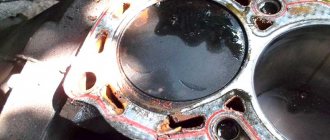
If you detect a leak of engine oil or coolant at the junction of the head with the Lada Priora cylinder block, remove the head and replace its gasket. A leak can also occur due to warping of the block head due to overheating.
You will need: a torque wrench, “13”, “17”, “19” keys, “10”, “13”, “17” socket heads, “10” hex key, screwdriver.
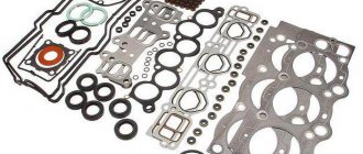
The head gasket is a one-time use unit, so each time the head is removed, the head gasket must be replaced.
- 1. Remove the decorative engine cover (see “Removing and installing the decorative engine cover”).
- 2. Set the piston of the 1st cylinder to the TDC position of the compression stroke (see “Installing the piston of the 1st cylinder to the TDC position of the compression stroke”).
- 3. Reduce the pressure in the power system if the work is performed immediately after a trip (see “Reducing fuel pressure in the engine power system”).
- 4. Disconnect the wire from the negative terminal of the battery.
- 5. Drain the coolant (see “Replacing the coolant”).
- 6. Remove the air filter (see “Removing and installing the Lada Priora air filter”).
- 7. Disconnect the heating hoses, the small branch of the crankcase ventilation system, the canister purge, the air supply hose, the wiring harness blocks of the throttle position sensor and the idle speed controller from the throttle assembly (see “Removing and installing the throttle assembly”).
- 8. Remove the throttle assembly of the VAZ 2170 (see “Removing and installing the throttle assembly”).
- 9. Disconnect the wiring harness connectors from the Priora ignition coils. Remove the ignition coils and remove the spark plugs (see “Replacing and servicing spark plugs”).
10. Disconnect the wiring harness block from the emergency oil pressure drop sensor...
11. ...from the coolant temperature sensor of the priority engine management system...
12. ...and phase indicator.
13. Loosen the clamps and disconnect the five hoses of the Priora cooling system from the thermostat pipes.
14. Disconnect the wiring harness connector from the coolant temperature gauge sensor.
15. Using a 13mm wrench, unscrew the nut securing the tip of the “mass” wire...
16. ...and remove the wire.
17. Unscrew the nut of the fuel hose fitting and disconnect it from the fuel line tube of the VAZ 2171.
The tip of the fuel line tube is sealed with a rubber ring. Don't lose it during disassembly. Replace a severely compressed or torn sealing ring.
18. Unscrew the screw of the pressure plate of the bracket securing the fuel line to the cylinder head and remove the plate.
19. Using a 10mm wrench, unscrew the fastening bolt...
- 20. ...and disconnect the “mass” wire from the block head.
- 21. Remove the intake manifold (see “Replacing the cylinder head cover gasket for the Lada Priora”).
- 22. Remove the cylinder head cover (see “Replacing the cylinder head cover gasket”).
23. Using a 5mm hex key, unscrew the fastening bolts and remove the front protective cover of the timing belt.
24. ...and remove the lid.
25. Using a 5-point hex key, remove the bolts securing the lower front timing belt cover...
26. ...and remove the cover.
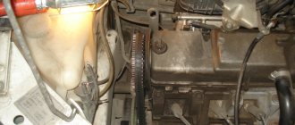
27. Using a 15mm wrench, loosen the bolt securing the tension roller VAZ 2171.
28. . and remove the timing belt.
29. While holding the camshaft pulleys of the VAZ 2170 from turning, remove the bolts securing the pulleys...
30. ...and take out the pulleys...
31. ...and remove the keys from the grooves of the shaft shanks.
To prevent the camshafts from turning when turning out the bolts securing the camshaft toothed pulleys, we recommend using the device shown in the photo.
The pulleys of the intake and exhaust camshafts have the same mounting dimensions, but a disk is attached to the pulley of the intake camshaft, which ensures the operation of the phase sensor.
32. Using a 15mm wrench, unscrew the fastening bolt and remove the tension roller.
Please note that there is a spacer ring installed under the roller.
33. Using a 15 mm wrench, unscrew the fastening bolt and remove the support roller VAZ 2170.
34. Using a 10mm wrench, unscrew the five bolts securing the rear protective cover of the timing belt.
35. . and remove the cover.
- Tightening procedure for cylinder head bolts
36. Using a 10mm hex key, unscrew the bolts securing the cylinder head to the Lada Priora cylinder block in the reverse order of tightening.
37. . and remove the cylinder head from the engine.
- Do not jam a screwdriver or other tools between the cylinder head and the cylinder block.
- It is more convenient to remove the cylinder head with an assistant, since it is quite heavy.
38. Remove the head gasket.
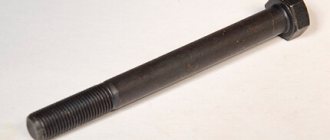
The cylinder head bolts become stretched with repeated use. Replace bolts whose length (excluding head height) exceeds 98 mm with new ones. Before installing the cylinder head, lubricate the bolts with a thin layer of engine oil.
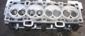
39. Clean the mating surfaces of the cylinder head and cylinder block (they must be dry and clean).
40. Remove oil from the threaded holes in the block for the VAZ 2172 head bolts.
If the oil is not removed from the threaded holes for the head bolts, cracks may appear in the cylinder block when the bolts are tightened because the oil is not compressed.
41. Check the presence of two installation sleeves in the sockets of the outer holes of the cylinder block for the head bolts. If, when removing the head, the bushings remain in the head or come out of the block sockets, press them into the block until they stop.
42. Place a new VAZ 2172 head gasket on the block. Using a used gasket is not allowed. Before installing the gasket, it is necessary to remove oil from the mating surfaces of the block and its head. The gasket must be clean and dry. Oil should not come into contact with the surface of the gasket.
43. Mount the head on the block, first making sure that the crankshaft and camshafts are in the TDC position (both valves of the 1st cylinder must be closed). Tighten the cylinder head bolts in four stages:
- 1st - torque 20 N m (2 kgf m);
- 2nd - torque 69.4–85.7 N m (7.1–8.7 kgf m);
- 3rd - tighten the bolts 90°;
- 4th - finally tighten the bolts 90°.
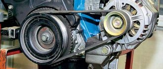
44. Install the removed parts onto the cylinder head and connect hoses and wires to it in the reverse order of removal. Install the Lada Priora intake camshaft pulley with the disk that ensures the operation of the phase sensor to the engine. Install the VAZ 2172 exhaust camshaft pulley in the same way. Adjust the tension of the timing belt (see “Replacing the timing belt and tension roller,” page 81) and the generator drive belt (see “Checking the tension of the generator drive belt”).
Consequences of incorrect cylinder head installation
Correct tightening of the cylinder head is very important, since the performance of the motor directly depends on it. The cylinder head acts as a cylinder cover, and any violations in its fit affect the processes occurring inside the power unit.
Insufficient tightening of the head leads to a drop in compression due to loss of tightness at the junction of the cylinder head with the cylinder block, burnout of the gasket, breakthrough of working gases from the cylinders and their entry into the channels of the lubrication or cooling systems, penetration of technical fluids into the combustion chambers, which in turn is negative affects the functioning of the power unit and can cause very serious damage.
Excessive tightening also does not bring anything good; in this case, damage to the head often occurs - cracks appear, or fasteners are destroyed - bolts break, threads break, etc.
Uneven or incorrect tightening often causes warping of the head, due to which gaps appear at the junction of it with the block, which leads to the same consequences as insufficient tightening.
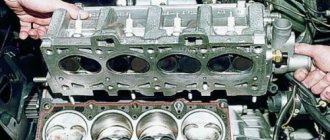
Let's move on to the cylinder block
We remove the pallet. Rotating the crankshaft as it is convenient for us, unscrew two bolts on each connecting rod cap. We use a TORX E10 head for this.
We take out the pistons along with the connecting rods. To do this, use the wooden handle of a hammer to press the connecting rod from below and lightly tap it to knock it up. We remove the old liners and buy new ones of the same size according to the markings on them. Here is another stone in AvtoVAZ’s garden, the owner has never climbed into the car from the interior or into the engine, but three pistons were of group “B” and one was “C”. It turns out that at the factory they re-sharpened one cylinder a little and simply put an enlarged piston there, no words. There are no options, we take group “C”, don’t sharpen the engine because of this. We will not touch the main liners either.
Part Features
The cylinder head is a structurally quite complex part. It is a massive plate in which there are channels for the circulation of fluids of the lubrication and cooling system, and technological holes - spark plugs, for injectors (in diesel engines), mounting holes.
Also on top of the cylinder head there is a so-called “bed” of the camshaft - a seat for its installation.
Despite its massiveness, the block head is a fragile part due to the voids inside, so excessive tightening force often leads to cracks in the walls and bridges.
For the manufacture of cylinder head, two types of metals are used - aluminum (the most common) and cast iron.
To secure the latter, steel bolts or studs with nuts are used. For example, the head of the UAZ 31519 block is secured with studs.
The difference in the materials used to make the head and its fasteners has one negative factor - different thermal expansion of the components when heated, especially for aluminum cylinder heads.
Uneven tightening of fasteners (nuts, studs, etc.) during thermal expansion leads to the appearance of excessive stress in the metal structure, resulting in warping of the head.
Priora connecting rod dimensions
By pushing the piston up to its entire length, the connecting rod strictly fixes the volume of the combustion chamber. From this we can conclude that the volume of the working cavity of the cylinder itself, in which the fuel burns, also depends on its length. That is, if the length is increased, the volume will become smaller. And if you shorten it, the size of the camera will increase accordingly. The factory engine comes with standard length connecting rods. It is 150 millimeters. It is measured from the axial point of the center of the head (pin attachment) to the same line of the lower part attached to the crankshaft. This size provides the motor with standard factory parameters. For example, engine displacement. It is 1597 cubic centimeters. Or as the owners say, the engine is “one and six”.
Bolt tightening conditions
When installing the cylinder head, it is important to comply with the tightening technology, which includes a number of criteria:
- Tightening order;
- An effort;
- Condition of fasteners (for example, studs with nuts);
Each engine has its own tightening order, which must be followed to ensure uniform tightening of the head to the block and to prevent the occurrence of stress on any surface areas. For example, on a VAZ 2105 it looks like this.
Force is another important factor for the correct fastening of this engine element. Attracting the plate is carried out in several approaches (their number differs on different motors), each of which is performed with its own force.
The cylinder head fasteners are tightened with quite a lot of force, which leads to them being pulled out. Therefore, on many engines, bolts cannot be reused; they must be replaced. But there are also motors for which replacement of fasteners is not necessary and their re-installation is possible.
All information regarding the cylinder head tightening technology is indicated in the technical specifications. documentation for the car, it is also often indicated on the packaging of head gaskets and fasteners.
Engine assembly
We wipe the crankshaft pins, cylinder mirror and connecting rod bearing seats with a clean rag; by the way, you can degrease them. We insert new liners into the connecting rod and cover so that the antennae of the liners fit into the grooves.
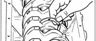
Lubricate the liners, crankshaft pins and cylinders with clean oil. We open the elastic bands in blocks as shown in the figure, the angle between them should be 120 degrees.
We put a mandrel on the piston to compress the rings, having previously lubricated it from the inside with clean oil. Not forgetting the direction, the arrow on the piston should be directed towards the front of the engine, insert it into our cylinder.
Turn the crankshaft so that the connecting rod is at the bottom. Lightly tap the wooden handle of the hammer to press the piston into the cylinder. Remove the spindle and push the piston until the connecting rod rests on the crankshaft. Place the connecting rod bearing cap on the bottom, remembering the marks. Tighten the connecting rod cover bolts to a torque of 5 kgf * m. We repeat the same with all other cylinders.
We put back everything that was removed from below. We blow air from above and clean the holes for the head bolts. We install a new head gasket and the head itself. Lubricate the bolts with a thin layer of oil, most importantly without fanaticism. We tighten the bolts in several stages in the reverse order of unscrewing, see the photo at the beginning of the article. The tightening sequence is as follows:
- first we tighten everything with a torque of 2 kgf * m
- then tighten everything with a torque of 7-8 kgf * m
- rotate 90 degrees
- rotate 90 degrees again
We install hydraulic lifters, camshafts and camshaft bearing cover. All rubbing surfaces are lubricated with clean oil. Before installing the camshaft bearing cap, lubricate the perimeter and rims around the spark plug wells with a thin layer of sealant. Tighten the bearing cover bolts in the reverse order of unwinding, with a torque of 2 kgf * m, see photo at the beginning. Well, let's install all the parts in the reverse order of removal. Fill in all the fluids and let's get started, it may not start right away, this is normal. At the first start it will smoke well until the oil on the cylinders runs out, we see that the oil pressure light goes out. Let it work for a minute and turn it off, suddenly we look where something has flowed. We turn it on several times, constantly increasing the operating range, bringing it to operating temperature, constantly checking the oil and antifreeze, and also pay attention to ensure that there are no extraneous noises. Let it rest for an hour and then idle again for about an hour, constantly monitoring the temperature. Well, if the break-in is abrupt, if not, you can only drive the first thousand kilometers, try not to increase the speed beyond 3000 and not tow.
General rules for performing work, methods used
There are a number of general rules that must be followed when installing the block head:
- It is important to strictly observe the tightening torque. For these purposes, a special tool is used - a torque wrench. It is not recommended to perform this operation with regular keys;
- The head bolts must be pulled smoothly, jerking is not allowed. Since the tightening force on the last approaches is significant, extending the wrench arm with a pipe can simplify the procedure and ensure smooth, uniform tightening;
- Before installing the bolts, you need to carefully inspect the condition of the threads on them. There should be no dirt or foreign particles on the coils.
- The threads of fasteners should be lubricated with engine oil before tightening. But you should not pour grease into the holes for the bolts (especially for “blind” holes), since in the future it will not allow the fasteners to be fully tightened.
Despite the fact that each engine has its own characteristics of tightening the cylinder head, the general technology of this operation is the same. In general, two methods are used to tighten fasteners:
- In several approaches, bringing the tightening force to the required value;
- Tightening the fasteners to a certain force (in one or more approaches), and then tightening the bolts twice to a certain angle.
The tightening method is selected based on the type of bolts.
The first method is used when using non-stretching bolts (these are not used now, but they can be found on old cars). But often this type of fasteners requires tightening after a certain period of engine operation in order to compensate for the shrinkage of the cylinder head gasket. But such fasteners are allowed for reuse, and more than once.
The second method of tightening the block is relevant for most modern cars. And all due to the use of tensile bolts (the so-called TTY type).
Such fasteners, due to elastic deformation, are able to compensate for thermal expansion of the head and shrinkage of the gasket, but for this they need to be put into deformation mode (in fact, just stretched a little).
To do this, it is necessary to tighten the bolts twice to a certain angle. On some cars this angle is 45 degrees, on others it is 90 degrees.
But after the elements are put into elastic deformation mode, they will no longer be able to return to their original state, and therefore their reuse is not allowed due to the high probability of destruction.
Cylinder head repair
We mark all hydraulic compensators with numbers using an ordinary clerical touch and put them away. An ordinary magnet will help you pull them out. We dry out the valves and remove the oil seals (valve seals), the valves into scrap metal, the oil seals into the trash. We clean all channels. We take the head for grinding, just in case. After washing it again with kerosene after sanding and blowing it with air, we begin to assemble it.
We arrange the freshly purchased valves in the sequence in which they will stand in the cylinder head and begin to grind in one by one. Lubricate the valve stem with clean oil and apply lapping paste to the edge.
We insert the valve into place and put a valve grinding tool on the valve stem. The stores sell a device for manual lapping, but since this is the twenty-first century, we are mechanizing the process. We take the old valve and cut off the rod from it, select a rubber tube for it of such a diameter that it fits tightly. The rod is in a reversible drill, one end of the tube is on it, the other is on the valve being ground in. At low speeds we begin to grind the valve, constantly change the direction of rotation and periodically press it to the seat or weaken the force. On average, the valve takes about twenty seconds. We take it out and wipe it. The valve is considered ground in if a uniform gray strip of at least 1.5 mm wide appears on the chamfer.
The same stripe should appear on the valve seat.
Video of manually grinding valves
For a sixteen valve head, everything is the same, only there are twice as many valves. After lapping, all valves and seats are thoroughly wiped and washed with kerosene to remove any remaining lapping paste. We check for leaks. We tighten the old spark plugs and put all the valves in place. Pour kerosene and wait three minutes, if the kerosene does not run away all is well, otherwise we grind the valves on this cylinder.
We had to grind four valves again, after which the kerosene stopped flowing.
We stuff new valve seals.
We put the valves in place and dry them. Before doing this, lubricate the valve stems with clean oil. After lubricating it with clean oil, we put the hydraulic compensators in place and, covering them with a clean cloth, remove the head out of sight. We're done with the cylinder head.
General procedure
Although tightening the cylinder head has many nuances and features, the general technology of the operation is not complicated, it is only important to comply with the conditions.
The general algorithm of work is as follows:
- We study the documentation (tightening order and force);
- We prepare the tool;
- We inspect and wipe the surfaces of the block and head, clean the mounting holes (with a rag or compressed air);
- We lay the gasket;
- We put the block head in place (the correct placement of the gasket and head is ensured by guide bushings);
- Lubricate the threads of the fasteners;
- We install the latter in the holes and tighten them by hand;
- We specify the drawing scheme, the number of approaches and the force of each of them, as well as the time of breaks between approaches (all this is indicated in the documentation);
- We make the first approach, observing the tightening order (for convenience, you can mark the bolts according to the order with a marker). In the photo is a VAZ 2103;
- We carry out all subsequent approaches.
Some nuances
The tightening torque is one of the main factors for the normal fit of the block head. But this criterion is influenced not only by the applied force, but also by the fasteners themselves:
- General condition of the bolts – new or used;
- Presence of lubricant on the threaded part;
- Thread condition.
The type of power plant (petrol, diesel), as well as the number of valves, does not affect the cylinder head tightening technology. But this does not mean that the force and tightening procedure are identical for all motors, and before seating the head, you should definitely study the conditions for performing the operation and all its features.
VAZ 2170 | Appendix: Tightening torques for threaded connections | Priora
| Detail | Thread | Tightening torque, N*m (kgf*m) |
| Cylinder head bolts | M12x1.25 | see section “Engine” |
| Intake pipe mounting nut | M8 | 20,83-25,73 (2,13-2,63) |
| Tension roller nut | M10x1.25 | 33,32-41,16 (3,4-4,2) |
| Camshaft bearing housing nut | M8 | 18,33-22,64 (1,87-2,3) |
| Camshaft pulley bolt | M10x1.25 | 45,82-56,6 (4,68-5,78) |
| Accessory drive housing bolt | M6 | 6,66-8,23 (0,68-0,83) |
| Cooling jacket outlet pipe mounting nut | M8 | 9,8-22,5 (1,0-2,3) |
| Main bearing cap bolt | M10x1.25 | 68,31-84,38 (6,97-8,61) |
| Oil sump bolt | M6 | 5,1-8,23 (0,52-0,84) |
| Balance shaft gear bolt | M10x1.25 | 45,82-56,6 (4,68-5,78) |
| Connecting rod cover nut | M9x1 | 43,32-53,51 (4,42-5,46) |
| Flywheel bolt | M10x1.25 | 70,81-87,47 (7,22-8,92) |
| Water pump mounting bolt | M6 | 5,10-8,23 (0,52-0,84) |
| Crankshaft pulley bolt | M12x1.25 | 87,47-108,05 (8,93-11,03) |
| Water pump inlet pipe mounting bolt | M6 | 4,2-5,1 (0,43-0,52) |
| Muffler exhaust pipe fastening nut | M8x1.25 | 19,6-24,5 (2,0-2,5) |
| Bolts for securing the front and rear suspension brackets of the power unit | M10x1.25 | 31,85-51,45 (3,25-5,25) |
| Nuts of bolts securing the suspension supports of the power unit | M10x1.25 | 28,08-45,3 (2,86-4,62) |
| Nuts for fastening the left suspension bracket of the power unit | M8 | 14,0-22,54 (1,43-2,3) |
| Bolt securing the oil receiver to the main bearing cover | M6 | 6,37-10,29 (0,65-1,05) |
| Bolt securing the oil receiver to the pump | M6 | 6,37-10,29 (0,65-1,05) |
| Oil pump mounting bolt | M6 | 8,33-10,29 (0,85-1,05) |
| Oil pump housing bolt | M6 | 6,97-8,61 (0,71-0,88) |
| Oil pump pressure reducing valve plug | M16x1.5 | 45,5-73,5 (4,6-7,5) |
| Oil filter fitting | M20x1.5 | 37,49-87,47 (3,82-8,92) |
| Carburetor mounting nuts | M8 | 6,6-15,4 (0,7-1,6) |
| Detail | Thread | Tightening torque, N*m (kgf*m) |
| Bolt securing the clutch housing to the engine cylinder block | M12x1.25 | 54,2-87,6 (5,5-8,9) |
| Clutch housing cover bolt | M6 | 4,7-7,7 (0,49-0,79) |
| Nut securing the clutch housing to the gearbox housing | M8 | 15,7-25,5 (1,6-2,6) |
| Bolt securing clutch to flywheel | M8 | 19,1-30,9 (1,95-3,15) |
| Detail | Thread | Tightening torque, N*m (kgf*m) |
| Hinge bolt on gear selector rod | M8x1 | 16,3–20,1 (1,66–2,05) |
| Gear selector mounting bolt | M6 | 5,1–8,2 (0,5–0,83) |
| Nut securing the gear shift rod clamp | M8 | 15,7–25,5 (1,6–2,6) |
| Nut of the rear end of the primary and secondary shafts | M20x1.5 | 120,8–149,2 (12,3–15,2) |
| Reversing light switch | M14x1.5 | 28,4–45,3 (2,9–4,6) |
| Bolt securing the gear fork to the rod | M8x1 | 11,7–18,6 (1,2–1,9) |
| Nut fastening the jet thrust to the power unit | M10x1.25 | 51–82,4 (5,2–8,4) |
| Speedometer drive fastening nut | M6 | 4,5–7,2 (0,45–0,73) |
| Ball joint race fastening nut | M8x1.25 | 15,9–25,8 (1,6–2,6) |
| Gear selector shaft mounting bolt | M6 | 7,8–12,3 (0,8–1,26) |
| Nut securing the rear crankcase cover | M8x1.25 | 15,7–25,5 (1,6–2,6) |
| Retainer plug | M16x1.5 | 28,4–45,3 (2,9–4,6) |
| Attaching the gear selector lever to the rod | M8x1 | 28,4–35,0 (2,9–3,6) |
| Nut securing the gearbox to the clutch housing | M8x1.25 | 15,7–25,5 (1,6–2,6) |
| Drain plug | M22x1.5 | 28,7–46,3 (2,9–4,7) |
| Clutch fork support | M8 | 15,7–25,5 (1,6–2,6) |
| Clutch release bearing guide bushing bolt | M6 | 3,8–6,2 (0,39–0,63) |
Common Mistakes
Despite the fact that automakers clearly indicate the procedure and nuances of tightening the cylinder head, many car enthusiasts make mistakes when assembling the engine. The most common of them are:
- Pouring oil into the mounting holes to lubricate the threads (the liquid is incompressible, so poured oil will not allow the head to be properly tightened);
- Over-tightening (exceeding tightening forces leads to damage to the cylinder head and the fasteners themselves);
- The use of damaged or inappropriate keys (the edges of the bolt heads may be torn off, after which it will be problematic to tighten or unscrew them normally);
- Use of unsuitable bolts as replacements (fasteners from different engines may differ in length, thread spacing, head height and diameter);
To avoid problems in the future, you should use only fasteners designed for a specific engine and fully comply with the work conditions.
Video “How to properly tighten cylinder head bolts”
In this video, a master with extensive experience shows and describes in detail how cylinder head bolts are tightened correctly. On a Lada Priora car with a 16-cell unit, work is carried out according to the same scheme.
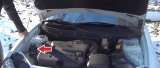
Today we took one of our old clients to Priora; as it turned out, the jammed pump broke the belt and, as a result, the valves were bent.
But progress at AvtoVAZ does not stop, and if on engines of the tenth family the valves simply fold, then even on the Priora 126 the connecting rods lose alignment and, if they are not changed, there is a high probability that the engine will start to eat oil, and therefore your money. Glory to the designers of AvtoVAZ!
But there are no breakdowns without good things; there are piston kits for 126 engines with grooves that do not bend the valve. In this article we will describe the procedure for repairing the cylinder head after a broken timing belt, as well as replacing the piston. Removing and installing the timing belt is described in this article, so we will not go into detail.
This procedure requires torque wrenches!
Features of the work performed using the example of some cars
To prove the proposition that each power plant has its own characteristics of tightening the cylinder head, let’s consider the nuances of performing work on specific models.
VAZ-2112 16 valves
A number of modifications of the VAZ-2112 were equipped with two types of 16-valve power plants (factory indexes - 21120 and 21124). These two motors, despite some design features, have identical head tightening technology.
These units use 93mm long tension bolts. In this case, reuse of fasteners is allowed, but under one condition - if their length does not exceed 95 mm (if it is longer, they should be replaced). 10 bolts are used to secure the head.
Tightening is carried out in three approaches:
- The bolts are tightened according to the order with a force of 2 kg/m;
- Turning 90 degrees;
- Repeated tightening to 90 degrees.
The drawing diagram is shown below.
Between the 2nd and 3rd approaches you need to take a 20-minute break.
Since these engines use tensile bolts, additional tightening is not required during vehicle operation.
VAZ-2107
On the VAZ-2107, all installed modifications of power units are 8-valve.
The block head is attached to them with 11 bolts, 10 of which are main, and 1 is an auxiliary side bolt (installed in the side protrusion).
On this car, tightening fasteners is also performed in three approaches:
- 10 main bolts are tightened in order with a force of 3.5-4.0 kg/m;
- The same bolts reach with a torque of 11.5-12.0 kg/m;
- The auxiliary is tightened with a force of 3.5-4.0 kg/m.
Additional tightening of the cylinder head is not required when operating the VAZ-2107.
"Samara", 10th family, Priora
On models of the Samara family (2108-21099), as well as VAZ 2110-2112 with 8-valve units, tightening is already performed in 4 approaches:
- Tightening with a force of 2.0 kg/m;
- Reaching with a moment of 7.5-8.5 kg/m;
- Turn 90 degrees;
- Repeated rotation by 90 degrees.
The break between points 3 and 4 is 20 minutes.
As for the VAZ of the “tenth” family, which are equipped with 16-valve engines, their tightening technology is the same as that of the VAZ-2112 (described above).
The same applies to the Lada Priora; on 8-valve units, a method with 4 approaches is used (VAZ 2108-21099), and on 16-valve units, 3 approaches are used (VAZ 2112 with a 16-valve engine).
"Volga"
On ZMZ-406 engines installed on the Volga, according to the automaker’s technical documentation, tightening the engine block head bolts is carried out in two approaches:
- With a force of 4.0-6.0 kg/m;
- With a moment of 13.0-14.5 kg/m.
But many car owners of this car note that this technology does not allow the cylinder head to be properly tightened, so they use techniques with a large number of approaches.
A common method is the cross method, performed in 4 stages and with the following efforts:
Subsequent tightening of the bolts is not required when operating on this engine.
Video “Installing and tightening the cylinder head on a Priora”
The assembly of the upper part of a 16 valve engine is presented in a video from the Expert R channel.
I encountered the following problem: I replaced the piston with a plugless automatic transmission. The diesel is gone. But on a hot engine, a knock appeared, which directly depends on warming up. The feeling is that the block is moving away and the piston-cylinder gap is coming out (during installation I made 3 hundred parts). So the essence of the issue is that there are two tightening methods that I came across in the literature, 1st - a torque of 20 N m (2 kgf m); 2nd - torque 69.4–85.7 N m (7.1–8.7 kgf m); 3rd - tighten the bolts 90°; 4th - finally tighten the bolts 90°. or Using a torque wrench, tighten the head mounting bolts in three steps - first with a torque of 20 N m (2 kgf m), then turn the bolts by 90° and then turn the bolts again by 90°. I pulled the first one myself. Is the question correct? If you have links to sources, please share.