When repairing or replacing the dashboard (instrument panel) of VAZ cars with a more convenient and modern version of VDO, made with LEDs, you will need connection diagrams and pinouts of panel connectors. For this purpose, the editors of 2SHEMI.RU have prepared a complete collection of panel contact pinouts for all popular models of this car.
The main symbols that are found on the dashboard of absolutely any car of the VAZ family are: speedometer, fuel gauge, tachometer and sensors to indicate engine temperature.
Where is the mass located?
When operating a car, it is important to know all the places where the mass of the VAZ 2114 engine is located. If a malfunction occurs in this direction, you can quickly detect the source of the problem and eliminate it accordingly. So, where is the mass of the ECU for the VAZ 2114? Let's try to understand this issue.
Where is the mass located on the VAZ 2114:
Battery weight of VAZ 2114
The negative battery branch consists of branches of wires of two types - thin and thick wire. The battery negative is directed to the motor housing using a thick wire. As a result of poor contact fastening, the charge will be supplied in a small volume, as a result, the starter will not be able to develop sufficient power, and the ECM will therefore fail, because it receives the required mass from the engine.
In order to check the negative charge connections between the battery and the engine, it is necessary to check the reliability of the two nuts, so you first need to loosen the nut from the outside and tighten the nut from the inside, and then screw the nut back on from the outside.
A thin negative wire is connected to the car body next to the battery. It plays the role of an energy source necessary for all consumers equipped in the car. To check, you also need to make sure the degree of tension of the nut both with the body and with the battery terminal.
Weight of engines VAZ 2114
Samar engines with a volume of 1.5 liters take weight from the engine body, from the mounting plugs, which are located to the right of the cylinder head.
Samar engines with a volume of 1.6 liters, or 1.5 liters equipped with a new type of ECM, take weight from a welded stud. The pin is attached directly to the metal body of the instrument panel near the floor tunnel in the area under the ashtray. When assembled at the manufacturer's factory, the stud is usually poorly secured and painted, as a result, during operation of the machine it can become completely loose, as a result, when the ventilation device is turned on, the electrical voltage of the system will drop, and the following devices will react accordingly: mass air flow sensor, air metering sensor, air pressure sensor.
Weight of the VAZ 2114 dashboard
In this version, there is a connection between the torpedo harness, the circuit from the mounting relay and fuse block, and the rear harness. This connection is located under the steering shaft mount. If the connection of this mount is not of good quality, problems may arise in the operation of the dashboard readings when the main energy consumers are turned on, for example: turn signals, headlights, etc.
- Electric motor heater weight
This ground connection is located under the instrument panel on the left side of the heater housing.
What is the weight of the VAZ-2109 engine with and without gearbox
If you need to remove the engine, then there are two options - contact a service station or dismantle the unit yourself. There are two ways to remove the engine - lower it down and raise the car, or do the opposite - pull out the power unit through the top. It is impossible to do this without help, since the weight of the VAZ-2109 car engine is quite large.
What power units were used on the VAZ-2109
This car’s own engine model, marked “2109,” never existed; power units were installed instead:
- 21081;
- 21083;
- 2108;
- 2111-80;
- 11183-20.
Initially, the VAZ-2109 received units 21081 and 2108, which were installed on it from 1987 to 1997. They were based on a carburetor that supplied fuel. These power plants were replaced due to a malfunction that was unpleasant for many car enthusiasts - when the timing belt broke, the valve covers were bent.
Model 21083 was also equipped with a carburetor; “nines” are most often found with it. This engine model was developed back in 1987, and began to be installed only in the nineties.
This version of the engine is a modified 2108. The main difference of the power unit is that if the timing belt breaks, the valve pistons do not bend.
Injection engine modifications were initially intended only for export. They were developed on the basis of the 21083 engine. The first version was 2111-80, which subsequently underwent a deep modernization in order to increase its power. The converted version was released under the marking 11183-20. Since 1998, cars with these engines began to be sold on the domestic market.
Engine weight and other characteristics
The lightest is the latest engine model 11183-20 - it weighs 112 kilograms.
The remaining modifications are heavier (almost 128 kilograms). Interestingly, the lightest modification in weight is the most powerful - it has 81 horsepower. The first power plants were much more modest in parameters - the 2108 had only 64 hp. s., and 21083 has 69 “horses”. What the power units have in common is the number of cylinders - all are equipped with four. Moreover, the first modification has a cylinder diameter of 76 millimeters, and subsequent modifications have a cylinder diameter of 82 mm. By volume, the engines have the following parameters:
- 2108 – 1.3 liters;
- 21083 – 1,5;
- 2111 – 1,6.
Engine 21081 was similar in basic parameters to the base one, but had low power - only 54 horsepower. An intermediate option, before the start of production of cars with a power plant from Kalina, was the injection 2111-80. The number of “horses” in it increased to 72, and the maximum speed reached 160 km/h.
Engine dismantling
You can reduce the weight of the power plant if you remove it without:
- Gearbox (its weight is about 30 kilograms);
- a head weighing approximately 10 kilograms.
As a rule, at service stations, power units are removed assembled with the gearbox, while during self-repair, dismantling is carried out without attachments.
Let's give an example of engine dismantling, which is described in the car's operating instructions. The peculiarity of the work in this case is that the engine is removed through the bottom of the car. The manufacturer recommends not to disconnect the box from it, but to install the car itself on a lift.
- Disconnect the terminals and then remove the battery.
- Drain the coolant and engine oil.
- Remove the crankcase protection.
- Disconnect the muffler and remove the air filter.
- Loosen the brake booster hose clamp that leads to the powertrain inlet pipe.
- Unhook the ground from the crankcase; to do this you will need to unscrew the fasteners.
- Remove the high-voltage wire from the central contact of the distributor cover.
- Using a screwdriver, turn the spring clip and remove the block with the wires coming from the contact socket of the distributor.
- Remove the fuel hose.
- Remove the clutch cable end from the clutch drive lever.
- Disconnect the wires from the traction relay, from the generator output and from the carburetor shut-off valve.
- Disconnect the air supply hoses to the throttle and the fuel hoses leading to the carburetor.
- Remove the spring from the throttle actuator.
- Remove the speedometer and accelerator drive cables from the valve covers.
- Unhook the block with the wire from the economizer, remove the oil pressure and liquid temperature sensors in the cooling system.
- Remove the heater outlet hose and transmission drive rod.
- Next, you will need to disconnect the remaining conductors from the box and move the drive shafts to the side.
- After the steering rod and other parts are disconnected, place a stand under the engine and unscrew the nuts of the rear mounting support, then the right front and left.
Before lowering the engine, check that you have disconnected everything from it. In order to remove the engine from under the car, you need to lift the front part of it.
Poor engine weight
If the following problems occur:
- If the battery is charged, the car will not start.
- The battery is not charging, the voltage is unstable, constantly fluctuating, but the generator is in perfect order. To reset the battery, you need to reboot.
The occurrence of these problems indicates that the car has a poor engine weight. It is from the battery that the positive charge is supplied to the starter, and the charge is supplied to the fuse panel located under the hood through a thin wire.
The negative charge from the battery goes to the engine, because This is the largest part of the car, namely from it to the rest of the devices.
If the ground is bad, the car has difficulty starting due to lack of current. If you apply charging, the voltage is set to a minimum and the car often continues to operate with the battery.
How to check the ground on the engine? It's easy enough to do.
To check, you will need a cigarette lighter, which is connected with one end to the negative of the battery and the other to the engine; the connection must be thoroughly cleaned. We start the engine, if the car starts more easily and the voltage has increased, this indicates the need to clear the ground.
Unstable operation of the engine at idle speed of the VAZ 2114 is one of the reasons for checking the mass; it may be accompanied by poor, weak contact, resulting in unreliable readings from car sensors, or an incorrect control action is transmitted to the idle speed regulator.
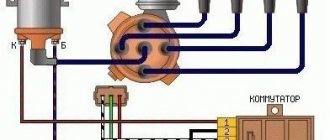
Tachometer diagram VAZ 2110 carburetor
VAZ tachometer connection diagram
Tachometers for carburetor VAZ cars
Connection diagram for the tachometer VAZ-2103, 2106, 2107:
2 – ignition coil;
3 – ignition distributor:
Let’s say right away that in terms of price/quality ratio, the best tachometers are standard ones.
Modern tachometers have come a long way from those that were mechanically driven. They are based on counting impulses. Such tachometers are installed on carburetor cars. The frequency of the signal is converted into voltage, which controls the needle.
On four-cylinder four-stroke engines, one crankshaft revolution will correspond to two flashes in the cylinders, that is, two pulses in the ignition circuit.
A tachometer designed for such an engine, of course, cannot be installed on another one, because the readings will be false. Therefore, select a tachometer in accordance with the make of the car. On foreign cars they often put a number indicating the number of cylinders.
How to choose the right tachometer for your car
Volga generator rectifier bridge with output to tachometer (1) and tachometer markings (2).
On diesel engines, the shaft rotation speed is calculated based on the frequency of the sinusoidal signal from the generator phase. In this case, tachometers have an adjustment potentiometer, which allows you to adjust the voltage indicating the signal frequency, which makes it possible to configure the device and correct its readings.
The biggest bonus of a generator tachometer is its versatility. It is suitable for an engine with any number of cylinders, but the main thing is that the car has a three-phase generator.
Tachometer VAZ 2110 - with four outputs: if it is on a car with injection, it is connected not to the ignition (input 2), but to the ECM controller with an additional output provided for this (input 1) - and in this case it reads the number of revolution pulses directly from the controller. It receives a signal about the position of the shaft. Here you can read more about the principle of operation of the tachometer.
Connection diagram for the tachometer on VAZ-2110 vehicles with a fuel injection system:
2 – trip computer;
3 – ECM controller;
4 – crankshaft position sensor;
5 – ignition module.
Scheme for connecting the tachometer on a modern Volga: 1 – tachometer; 2 – generator warning lamp; 3 – generator; f – phase output (to the tachometer).
Find out more about how to connect a tachometer here
Schematic electrical diagrams, connecting devices and pinouts of connectors
The first car from the Zhiguli family equipped with a tachometer was the VAZ 2103. Neither 2101 nor 2102 had such a device. The tachometer is used to measure the crankshaft speed. It is a revolution counter, showing their number by deflecting the scale needle to a certain angle. The tachometer is also indispensable when setting up the carburetor - its indicators are taken into account when adjusting the idle speed and the quality of the fuel mixture.
No weight on the engine
If there is no ground on the engine, it is necessary to check the quality of all electrical system contacts coming directly from the engine housing.
Or you need to check the condition of the stud, because... The manufacturer does not process this type of equipment in any way other than painting, so they are often susceptible to oxidation or corrosion. As a result of using low-quality parts, voltage drops in the system, which is accompanied by a lack of mass on the engine, resulting in problems in the operation of the machine.
Travel speed
The speedometer is one of the most important indicators. In addition to the speed of movement, it also shows the distance traveled. On models produced before 1995, this is mainly only the total mileage value. Later models have a daily trip counter and a button that allows you to reset it.
If malfunctions occur in the speedometer, you should check the fastenings and condition of the flexible shaft. Pay attention to bends, the radius of which should be more than 10 mm. Replace the drive cable; if this does not help, then installing a new speedometer is required. The price of services in the salon for this repair is small, so it is better to immediately contact specialists.
Troubleshooting
For uninterrupted operation of the battery, the system must be equipped with good quality wires; in this case, copper wires are the most suitable, since they have the best characteristics when operating under voltage.
The thin positive wire coming from the generator must be replaced with a thicker wire.
To protect the existing mass and ensure longer and more trouble-free operation, it is necessary to treat all existing connections and terminal contacts with a special lubricant that has an anti-oxidation function.
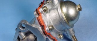
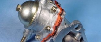
Where is the fuel pump located on the VAZ-21099 injector
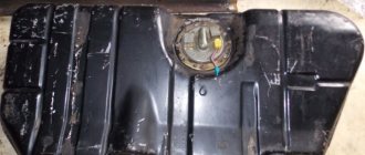
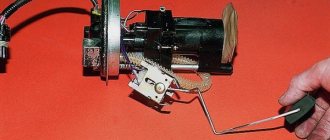
Removing and installing a gasoline pump (PG) is not a difficult job and does not require extensive plumbing experience or high qualifications. But if you don’t have to look for a fuel pump on carburetor cars for a long time (it is located on the engine, under the hood), then a beginner may not find it on the injector on the first try. Where is the fuel pump located on the VAZ-21099 sedan injector? Let's figure it out step by step:
- we move the front seats in the car forward as much as possible to free up space in the rear;
- open the rear left door of the car, find a small hinge on the rear sofa, which is located at the junction of the “seats” approximately in the middle of the cabin;
- pull the loop up, thereby raising the back of the lower seat;
- under the carpet we see the gas tank flap;
- unscrew the two fastening screws, remove the hatch and find the fuel pump underneath.
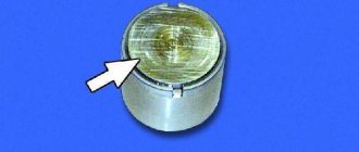
Where is the fan relay VAZ-21099 injector
Quite often a problem arises with the Ninety-Nine when the engine fan does not turn on and the coolant begins to boil. If such a malfunction occurs, first of all they check the functionality of the fan itself by applying voltage directly to it from the battery, but there may be other problems.
In order to check the entire circuit, it is important to find where the VAZ-21099 injector fan relay is located, since it is responsible for turning on the airflow. We find this part in the front of the car, on the passenger side, it is installed under the glove compartment, at the passenger’s feet.
The required relay in the picture is indicated by an orange circle, and here you will also find a fuse that blows when the cooling fan is short-circuited.
Travel speed
The speedometer is one of the most important indicators. In addition to the speed of movement, it also shows the distance traveled. On models produced before 1995, this is mainly only the total mileage value. Later models have a daily trip counter and a button that allows you to reset it.
If malfunctions occur in the speedometer, you should check the fastenings and condition of the flexible shaft. Pay attention to bends, the radius of which should be more than 10 mm. Replace the drive cable; if this does not help, then installing a new speedometer is required. The price of services in the salon for this repair is small, so it is better to immediately contact specialists.
Where is the mass of the VAZ-21099 injector (main)
If the starter turns weakly, or the engine does not start at all (clicks occur when starting), various electrical problems arise, it is likely that the car does not have normal weight. Fixing such a problem is generally not difficult, but to do this you still need to know where the mass of the VAZ-21099 injector is located.
The main mass (thick) wire goes from the negative terminal of the battery to the engine, the thinner wire is connected to the car body, all energy consumers in the car depend on this connection. If the contact is poor, the battery stops charging normally; in order for the starter to turn well, you should check the reliability of these contacts and clean the metal from oxidation. If, due to a heavy load (for example, when installing additional equipment), the ground wire heats up and there is clearly not enough of it, you can “lay” additional ground almost anywhere where good contact between the engine and the body is ensured. The main thing is that this wire has a sufficient cross-section.
Tachometer malfunctions - finding the cause yourself
Use a multimeter and know the wiring diagram of your car.
It is better to take measurements with a multimeter. To operate, you must know how to use it. The “tester” makes it possible to measure power, “ground” and “ring” the main wire for a break.
Power measurements are carried out in DC mode (select a range within 20 Volts). In this case, “-” is always present, “+” appears after the ignition is activated. Ideally, the signal wire shows pulses while the crankshaft is rotating.
Breaks are looked for by setting the ohmmeter function on the multimeter. If the problem is in the contacts, move the harness/connector.
Is the tachometer not working properly? Sometimes this is due to design defects in the car. For example, it happens like this: the operation of a generator, when the current on the excitation winding is regulated by alternating voltage, is accompanied by “vibration” of the needle (typical of old VAZ cars). This defect can be corrected by changing the connection diagram or updating the dashboard.
Where is the starter relay located?
Just like the engine cooling fan, the starter is controlled by a relay, and its malfunction can cause problems:
- when you turn the ignition key, nothing happens, the engine does not show any signs of life;
- When I try to start the engine, clicks are heard, but the starter does not crank.
Finding out where the starter relay is located on a VAZ-21099i car is very simple; to do this, you just need to open the hood of the car and look behind the air pipe of the injection engine; the part you are looking for is shown below in the picture.
Starter malfunctions and repairs
KamAZ is a very repairable truck. If malfunctions occur, you can fix the breakdown yourself. Let's look at typical problems with the St-142b starter:
- When the ignition is turned on, the device does not work. In this case, it is necessary to check the winding of the traction relay. There may be a short circuit or open circuit. Depending on the nature of the breakdown, it is necessary to replace the retractor. Breakdowns can also be caused by a lack of contact between the brushes and the commutator. In this case, check the pressure of the brush springs. If it is less than 1.8 kgf, the element is replaced with a new one.
- The traction relay does not work. It is necessary to check the coil of the additional relay and make sure that the pull-in winding is intact. They also check the reliability of contact in the circuit and all connections.
- When the starter is turned on, characteristic clicks of the additional relay appear. The drive gear jams on the flywheel crown. Perhaps the reason is hidden in an incorrectly adjusted moment of closing the contacts of the traction relay. How to fix this? The gap is set between the gear and the thrust washer. Next, check the operation of the mechanism. If the symptoms recur, the starter drive end or flywheel ring teeth may be clogged. There are several ways to troubleshoot the problem. The first is to restore the teeth using surfacing. The second is to replace the flywheel ring or drive gear. The third method involves cleaning out irregularities on the teeth.
- During operation, the armature rotates but does not interact with the flywheel. The crankshaft does not turn. In this situation, it is necessary to check the integrity of the flywheel teeth, as well as the drive gear. The starter is also re-adjusted.
Where is the temperature sensor located?
If the temperature sensor does not show on the instrument panel, there is a high risk of overheating the engine, since the instrument panel does not inform the driver about the heating of the internal combustion engine coolant. Of course, the instrument panel or electrical wiring may be faulty, but most often the temperature sensor (DTOZH) on the engine itself refuses to work.
Where is the temperature sensor located on an injection car 099? Of course, you need to look for it in the engine compartment:
- open the hood;
- we find the wiring that is located between the rear of the engine valve cover and the air filter housing;
- where the DTOZH is located can be seen in more detail in the following photos.
Pinout of the dashboard of VAZ2113, 2114, 2115
There are 26 contacts on the VAZ-2114 instrument panel, each of which is responsible for the operation of the indicators of this panel. If a plus is supplied to the panel, then each contact displays information about the state in which the car is currently located.
White block (X1)
Red block (X2)
- Housing (weight) - black
- To ambient temperature sensor - cyan-magenta
- Tachometer (low voltage input from ECU) - brown/purple
- Fuse F16 (to terminal 15 of the ignition switch) - orange
- Tachometer (high voltage input from coil) - yellow
- Housing (weight) - black
- To fuse F3 of the mounting block (+battery) - white-purple
- Instrument lighting control - white
- Coolant temperature sensor. - green-white
- Turn signal RIGHT - blue
- To fuse F10 of the mounting block - brown
- Turn signal LEFT - blue-black
- Brake fluid level - pink-blue
- Check Engine Light to ECU Controller - White-Purple
- To the trip computer - brown
- To the ECU controller - pink and black
- Speed sensor - gray and yellow
- To the fuel gauge sensor - orange
- To the fuel gauge sensor - pink
- To the parking brake switch - brown-blue
- Fuse F14 of the mounting block - green-black
- Alternator terminal "D" through fuse panel - brown and white
- Hazard switch
- Oil pressure sensor - blue
- To terminal “50” of the ignition switch - purple
In addition, special indicators and signal sensors are installed on the instrument panel, and the panel itself is controlled by a special electronic unit. Having disassembled the instrument panel, you can see that there are two pads inside it: red and white. And all inputs, outputs and fuses are connected to the plug. If the sensors fail, they will need to be replaced. It is also better to replace damaged or oxidized wires. Indicator lights, like any other, sometimes burn out. Undoubtedly, they need to be replaced with whole ones. Along with them, the lamp sensor often burns out.
VAZ 2114 instrument panel connection diagram
- rear window heating switch;
- rear fog lamp switch;
- switch for headlights and direction indicators;
- mounting block;
- wiper switch;
- fog light switch;
- on-board control system display unit;
- instrument panel harness block to additional harness;
- instrument cluster;
- instrument panel harness connector to the on-board computer harness;
- instrument panel harness connector to the ignition system harness;
- instrument panel harness connector to the side door harness;
- fuse 16 A;
- fuse 16 A;
- ignition switch;
- lighting switch;
- heater electric motor;
- additional resistance of the heater electric motor;
- ignition switch unloading relay;
- rear fog light relay;
- starter relay;
- socket for connecting a portable lamp;
- cigarette lighter;
- instrument panel harness connector to the glove compartment lamp wiring harness;
- illuminator;
- illuminator;
- illuminator;
- heater switch;
- instrument lighting regulator with rheostat;
- brake light switch;
- horn switch;
- hazard switch;
- heater control lamp;
- fuse 16 A;
- seat heating relay;
Useful: Pinout of twisted pair network 8 wires - color scheme
Another variant of the connector pinout diagram
- checking the brake fluid level indicator. If you apply +, the brake light will light up. You can connect it to the red wire of the ignition switch, then, just like on 2110/2114, the lamp will be checked when the starter is turned on.
- Hazard warning lamp will light up when + is applied.
- high beam lamp, connect to the green-black wire.
- fuel level indicator, connect to the pink-red wire.
- to the speed sensor.
- speed signal output to the on-board computer. If there is one, then take the speed signal from this contact.
- Brake fluid level indicator, connect to the pink-blue wire near the lamp above the cigarette lighter. In the VAZ-2107, the lamp works the other way around: the sensor connects the lamp to ground and it lights up. You will have to either leave the lamp where it is, or in the new device, solder the lamp to + and swap the diodes (in this case, to check the lamp, pin 1 must be connected to ground, for example, to the parking brake lamp), or remove the black wire from the sensor on the tank, and connect instead the orange one from the EPHH unit, or the blue one from the ignition coil, while the diode in the wiring (between the beard and the glove compartment) must be disconnected; if this is not done, there will be a short circuit.
- left turn lamp, connect to the blue-black wire of the steering column switch block.
- Right turn lamp, connect to the blue wire of the steering column switch pad.
- instrument lighting, connect to the white wire.
- ground, connect to the black wire.
- power supply of devices, connect to the orange wire.
- if the device is simple (without microcircuits, etc.), then connect it to the blue-red wire (fuel reserve lamp), if there is a display under the tachometer, then connect it to the temperature sensor (take from a VAZ-2114, one contact to the device, the other to ground, place it either in the passenger compartment or in the engine compartment, but far from the engine and so that the wind does not blow).
- ground, connect to the white-black wire.
- low-voltage tachometer input (from the ECM), connect to the brown-blue wire.
- high-voltage tachometer input (from the coil), connect to the brown-blue wire.
- If there is a display under the speedometer, then connect it to the red and white wire at the brake light switch.
- coolant temperature gauge, connect to the green-white wire.
- outdoor lighting lamp, connect to the yellow wire.
- carburetor choke cover lamp, connect to the gray-orange wire.
- go to the ECM lamp. If the machine is injection, then connect one of the contacts to the orange wire, and the other to the remaining one.
- go to the ECM lamp. If the machine is injection, then connect one of the contacts to the orange wire, and the other to the remaining one.
- power supply of devices, connect to the orange-blue wire.
- handbrake lamp, connect to the brown wire.
- battery charge lamp, connect to the brown-white wire.
- low oil pressure lamp, connect to the gray-blue wire.
Where is the speed sensor located?
The speed sensor (DS) on front-wheel drive VAZ cars reads pulses depending on wheel speed and transmits the data to the electronic control unit (ECU). When braking the engine, the fuel supply is turned off with the help of the diesel engine and the computer, thus achieving more economical operation of the internal combustion engine. If the sensor is faulty, an error code is recorded, gasoline consumption increases slightly, and idle speed decreases, especially during heavy braking. It is difficult to immediately detect where the speed sensor is located, since it is hidden under the air filter housing (AFC).
We find the part we need as follows:
- open the hood of the car;
- Using a 10mm wrench, unscrew the two KVF fastening bolts;
- loosen the clamp of the air “corrugation”, disconnect the “chip” with the wires;
- we take out the KVF, now the sensor has already appeared in the field of view, it is located on the gearbox (gearbox) housing, wires are connected to it, connected using a connector.
VDO instrument panel
Glowing VDO instrument panel from VAZ 2110
I missed the Latvian illuminated instrument cluster (CI) - I didn’t buy it in the summer of 1999, when it cost 600 rubles. And now the situation with them is quite tense, or more precisely, “... there is no delivery and is not expected.” They say that they are in Tolyatti, but for $80 with a speed sensor. Expensive…
However, in markets and stores there is an abundance of VDO instrument clusters for the VAZ 2110 car, model 2110-3801010-02, which is also installed on the 115 VAZ model. In relation to the “eighth” panel, it has disadvantages:
- Doesn’t fit very well; you’ll have to cut the torpedo visor, otherwise some of the lamps will not be completely visible;
- There is no built-in BSK (on-board control system);
- It is necessary to select a fuel level sensor with the appropriate resistance, otherwise the indicator may be “slightly misaligned”.
Otherwise there are only advantages
- All instruments are more accurate, especially noticeable in the fuel level and coolant temperature sensors;
- The speedometer and tachometer are located in the center, all arrows are controlled by stepper motors - the movement of the arrows is smooth;
- The fuel light doesn't blink like crazy, because... it is ignited by electronics, and not by a contact in the tank;
- The total and daily mileage are displayed on the LCD display - when the car is not started, the mileage is not visible on the instrument panel. Relevant for new cars.
- There is a self-diagnosis mode - you need to turn on the ignition while pressing the reset button for the daily mileage counter.
Another plus: the speedometer cable becomes unnecessary, which often makes various sounds - sometimes it clicks, sometimes it clicks... True, I also had to buy a DS (speed sensor, since I have a carburetor car). The sensor needs to be taken only with an iron pin and a connector identical to the connector of the Hall sensor - it is easier and much cheaper to buy a chip for it.
Connection
Three chips fit the standard CP: white (X1) and red (X2), also one smaller red one (for BSK). Before changing the wires, a bundle of wires from the red block was pulled through the window in the dashboard next to the wires of the white block. Otherwise, you won’t be able to remove the dashboard later—tangled wires won’t allow it.
Where is the fuel filter located?
The fuel filter (TF) on the VAZ-21099i is designed to clean gasoline from debris, dirt and various impurities; it is a monolithic structure with a rigid metal body and a filter element inside. The frequency of its replacement is every 20-30 thousand km of the distance traveled, also if the car begins to move jerkily, and diagnostics showed that the fuel pump is clogged.
It’s easy to find out where the fuel filter is located; to do this, you need to install the car on an inspection hole or a car lift. The TF is located on the bottom of the body, next to the rear beam and the gas tank, and is secured with a special clamp, which is tightened with a bolt and nut.
Before you start changing the filter, you need to relieve the fuel pressure, otherwise when you unscrew the fuel fittings, gasoline will splash under high pressure. You can relieve pressure in the line using a special nipple located at the rear of the fuel rail. Before starting such an operation, it is necessary to prepare a plastic container into which gasoline should be poured, then unscrew the safety cap.
To release the pressure, you can use a standard flat-head screwdriver; when you press the nipple valve, gasoline will come out of the system.
After removing fuel from the line, we proceed to replacing the fuel pump.
Related articles:
- The influence of the fuel vapor recovery system on the operation of the Lada Kalina engine. Modern technologies are developing, equipment is becoming more complex and sophisticated, and progress does not bypass motor vehicles. Carburetor cars were very simple, and understanding them [...]
- Front spar of the VAZ-2109 - replacement, repair, cost of work The VAZ-2109 is a car that does not have a strong body; iron corrodes quite quickly, and almost all body parts rust. Replacement of the front side member is required […]
- Features of replacing the VAZ-2114 oxygen sensor, signs and causes of malfunction In connection with tightened environmental standards, all cars began to be equipped with additional systems that reduce the toxicity of exhaust gases, and on almost every car with […]
One thought on “Location of components and parts on the injection car VAZ-21099”
I have a fan relay on a 2109 injector, located to the left of the one marked in the photo
How the mass of the ECU and the mass of the engine - body are arranged, where it is located and how to check it. It is these interesting questions that we will address on this page.
The topic is really interesting and not as simple as it seems at first glance.
It would seem that there is nothing complicated here - a simple circuit and a rather thick wire, with which it is unlikely that anything can happen. But not everything is so simple, and we will “talk” about this further.
ECU weight
A reliable ECU ground is very important for the proper operation of the engine management system and the engine as a whole.
It would seem to be a primitive and reliable design that can serve well for years. But in reality this is far from the case.
It is very difficult to list all the possible problems that can arise due to poor ECU mass, since it can affect anything. But the main problems can be divided into two points:
- Incorrect collection of information from engine control system sensors. Personally, I had to deal with incorrect MAP sensor readings. It gave inflated barometric pressure readings precisely because of the poor weight of the ECU.
- Since almost all modern engine control units are able to adapt to real operating conditions, as a result of incorrect collection of information from sensors, adaptation leads to engine malfunctions. This is why for many, after resetting the adaptations, the engine begins to work much better. But then the problems return as the ECU adapts again. And again this does not happen quite adequately.
Where is the ECU ground located?
The ECU mass is usually arranged like this. Separate ground wires are removed from the ECU connector and connected to the engine via the starter mounting bolt. Ground wires are usually black
Everything is simple and reliable. But in reality, over time, the voltage begins to drop in this section of the circuit, slowly but surely, disrupting the operation of the system.
Therefore, this unit must be periodically checked and maintained. We will look at how to do this further.
Weight between engine and body
Line “31”, popularly called “ground”, “minus” or “negative circuit”, is very important for a car. And not only for electrical equipment, but also for many other systems, including the engine or automatic transmission.
Almost all cars have a single-wire on-board network system and the role of the “minus” in this circuit is played by the metal parts of the body. This greatly reduces the number of wires and reduces the cost of the car.
It turns out that all participants in this chain have their own connection to the body - instrument panel, headlights, ECU, engine, etc.
Despite the visual integrity of these connections, over time, due to oxidation and corrosion, the contact slowly and imperceptibly deteriorates, which leads to voltage drops when powerful consumers are turned on or disruption of the system.
I would divide the mass connections into main and local. Let's say that the connection of the head light masses is local and if this connection is disrupted, only the head light will suffer. But if the ground contact from the battery to the body is broken, the entire on-board network will suffer, and this may cause problems in the operation of the engine and other important components and assemblies.
This is how the voltage of the on-board network with problematic masses looks like on the diagnostic graphs
And here is the graph after mass prevention of battery - engine - body
High instrument panel
According to the diagram presented below, the VAZ 2109 with a high panel has the following components.
High dashboard
Item number
What is this
Hazard switch
Windshield wiper and washer control lever
Central nozzles of the interior heating and ventilation system
On-board computer (not available on all trim levels)
Glove compartment lid (glove compartment)
Side nozzles of the interior heating and ventilation system
Speaker (loudspeaker) trim
Power window switches (available on certain trim levels)
Control panel for heating and interior ventilation system
Gearbox shift lever
Hand brake lever
Carburetor choke handle
Horn switch (horn)
Instrument panel light switch
Front seat heating switch (available as standard)
Rear fog light switch
Front fog lamp switch (not available on all trim levels)
Rear defogger switch
Hood lock drive lever
Turn signal and light control lever
Outdoor optics switch
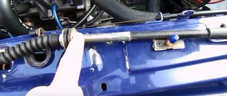
Where is the mass located: engine - battery - body
On most cars, the engine-body mass has a primitive appearance and is made of two pieces of cable connected together by crimping on the negative terminal of the battery
This crimp connects two wires. One goes to the engine and is secured with the starter mounting nut...
...and the second one on the body in the area of the left wing
It would seem that this is the simplest and most reliable chain that will serve well for years. But this is not at all true and it’s all to blame for the weak points in this design, which do not withstand the test of atmospheric influences.
How to check mass on a car
In fact, only a small group of motorists pay enough attention to this issue. Others begin to think about it when, when the cooling fan or headlights are turned on, the engine speed begins to sag, or when the rear window heating is turned on, the engine begins to tremble, transmitting vibration throughout the body.
But even at this stage, many limit themselves to a banal inspection and tightening the ground connection nuts on the engine and body. Everything is screwed down - that means everything is in order.
Then the car begins to jerk for no apparent reason, idle speed freezes, misfires, security system glitches, and so on, until the starter fails at the most inopportune moment. But even here, many will not go check the masses, but will run to the store for a new starter. After all, the wire to the starter is intact and there is voltage, but it, a radish, does not turn.
Replacing the starter, of course, does not help. As a result, the still-living battery goes into recycling and the situation seems to have improved, but after a couple of days the starter fails again and you begin to believe in brownies and otherworldly forces that have nothing better to do than cause damage to someone else’s car.
But, fortunately, reason wins and the advice of a good man is remembered - to check the masses.
Again, what's so difficult about this? It is necessary to check the resistance from the engine to the body.