Description of design
Steering elements : 1 — right steering rod assembly; 2 — right steering gear support; 3 — steering gear support bracket; 4 — intermediate cardan shaft; 5 — electric amplifier; 6 — steering wheel; 7 — steering column pipe; 8 — left steering gear support; 9 — steering mechanism; 10 — left steering rod assembly
The steering is safety-resistant, with electric power steering and a height (tilt) adjustable steering column. Steering mechanism is rack and pinion type with variable gear ratio. The mechanism is secured in the engine compartment on the front panel of the body with two brackets through rubber supports. The left support secures the steering gear housing from turning. The fastening bolts are welded, two on each side of the front panel.
Steering mechanism with rod assembly : 1 - outer tie rod end; 2 — adjusting rod; 3 — inner tie rod end; 4 — right protective cap; 5 — steering gear housing pipe; 6 — cover; 7 — locking plate of the tie rod mounting bolts; 8 — gear shaft; 9 — steering gear housing; 10 - left protective cap
The steering gear housing is cast from an aluminum alloy. On the right side, a pipe with a longitudinal window is inserted into the crankcase, secured with a nut. A helical drive gear (pinion shaft) is installed in the crankcase, which meshes with the rack.
The rack has helical teeth with variable pitch : zone 1 - with fine pitch, zone 2 - with coarse pitch
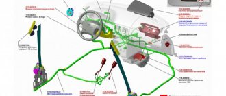
Steering column with electric power steering : 1 - input shaft; 2 - column pipe; 3 — column bracket; 4 — electric amplifier; 5 — electric amplifier control unit; 6 — steering column tilt adjustment lever; 7 — tie rod; 8 — rear bracket for electric amplifier; 9 - spring; 10 — output shaft; 11 — bolt-axle; 12 — front bracket for electric power steering; 13 — power connector of the control unit; 14 — control connector of the control unit; 15 - nut
To reduce the load on the gear shaft and its bearings under extreme operating conditions, a plastic gear bushing with a metal support plate is inserted into the crankcase. The gear shaft rotates on two bearings: the front (at the end of the shaft) is a needle bearing, the rear (closer to the steering column shaft) is a ball bearing. Since axial loads can be high in helical gearing, a thrust roller bearing is additionally installed on the drive gear shaft, consisting of a plastic cage with rollers, lower (inner) and upper (outer) rings. The lower bearing ring is pressed onto the drive gear shaft until it touches the inner ring of the ball bearing, and the upper ring is installed in the crankcase cover. In addition, the crankcase cover presses the outer race of the ball bearing against the end of the bearing seat. The drive gear seal is installed in the cover, and there is an O-ring between the cover and the steering gear housing. The entry of dirt into the connection between the shaft and the cover is prevented by a protective cover (boot) placed on the drive gear shaft. The rack is pressed against the gear teeth by a spring through a stop sealed in the crankcase with a rubber ring. To reduce friction, a plastic insert is installed between the stop and the rack. The spring, in turn, is tightened by an adjusting nut (internal octagon “24”). At the manufacturer's factory, when assembling the steering mechanism, the required clearance in the engagement of the rack and gear is set, after which the crankcase threads are cored (pressed) at two points (without damaging the nut). The right end of the rail rests on a plastic bushing, which is inserted into the pipe behind the longitudinal window. Adjustment of the gap between the gear and rack is carried out after disassembling the steering mechanism or if a knock occurs during operation. The gap can only be adjusted with the steering gear removed. The crankcase pipe of the mechanism is covered with a rubber corrugated cover. The inner tie rod ends are attached to the rack with bolts passing through the connecting plates, the spacer bushings of the rubber-to-metal joints and the tie rod support mounted on the rack. The spontaneous loosening of the bolts is prevented by a locking plate placed on the bolt heads. To lubricate the gear, rack and bearings, FIOL-1 grease is used (approximately 20–30 g for the entire mechanism).
Steering wheel angle adjustment lever with tie rod
The steering output shaft is connected to the gear shaft through an intermediate shaft, which has cardan joints at the ends. The steering column bracket, attached with four nuts to the body bracket, is pivotally connected to the steering column itself, which allows you to change the angle of the steering column. At the front, a front bracket is attached to the electric power steering housing with screws and is connected by two axle bolts to the steering column bracket. At the rear, a rear bracket is attached to the electric power steering housing, to which the steering column pipe is welded, and two guide plates with slots are welded to the steering column bracket. A tie rod passes through the slots of the guide plates of the steering column bracket and the spacer sleeve of the rear bracket of the electric booster, at one end of which a lever is screwed (special left-hand thread), and at the other there is a self-locking nut (right-hand thread). When the lever is turned down, it unscrews from the stud. In this case, the tightening force in the connection between the guide plates of the steering column bracket and the rear bracket of the electric power steering is weakened, which allows you to manually change the position of the steering column. Thus, the column can rotate in a vertical plane relative to its bracket, allowing you to adjust the position of the steering wheel. The movement of the steering column is limited by the length of the slots in the guide plates. After installing the steering column in the required position, the lever is turned up and the connection is tightened, fixing the column. Two springs are installed between the rear bracket of the electric power steering and the steering column bracket, which pull the column to the upper position when the tightening force in the connection is loosened.
Video
This video shows how to repair the steering mechanism on Kalina.
Knock in Kalina steering rack. How to remove.
Installation of Kalina steering rack.
Repair of the steering column gearbox and the RR itself on Priora, Kalina, Grant.
How to install a steering rack from Kalina 2 to Kalina 1.
Steering rack for Lada Kalina Sport with a gear ratio of 3.1 instead of 4.02.
Do-it-yourself repair of the steering rack, but not Kalina, but Daevoo Sens / Daewoo Sens.
Kalina control rack - VAZ 11183 Kalina rack repair
Have you ever had a chance to monitor knocks and noises from the side? Probably it happened. They changed the control tips, changed the ball tips, even changed the springs with support bearings, but does the knocking continue? It's time to tug, make sure there is free play and start sorting out the rack. In this article I will talk about repairing the VAZ 11183 rack, but the development is identical to all other VAZ front-wheel drive racks.
The most interesting thing is that these motherfuckers from AvtoVAZ do not fundamentally change anything except the gearbox housing, I bought a repair kit 2110-2112, the rack is listed in catalogs as 2110, but the splined part is longer than 2110, and the gearbox is slightly different, so just change Unfortunately, 11183 for 2110 will not work, although 2110 costs 2500 in my town, and 11183 5500 costs 6000 rubles. The difference per pocket is very noticeable.
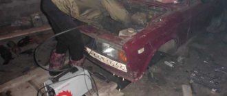
Well, it doesn’t fit and doesn’t fit, so we give the engineers a hard time and start disassembling it. Unfortunately, there won’t be a photo for the article, because I was up to my elbows in mud and didn’t want to wash myself for the sake of pictures, but I’ll try to describe everything carefully.
Removing the steering mechanism.
1. For convenience of work in the future, and so as not to climb into the interior with stains, unscrew the bolt securing the splined connection from inside the cabin (you will see it near the floor of the control shaft).
2. We lift the car on a lift, throw it down, and knock out the control tips from the steering knuckles.
Why is it needed and its device
ESD is an electrical mechanism that reduces the control force with which the driver turns the steering wheel. It turns out that this cunning device takes on most of the effort, leaving the driver responsible for the safety of the maneuver. The design of the EUR is as follows:
- Electronic control unit and electric motor;
Controller and peripherals
- Steering wheel;
- Output/input shaft;
- Studs, nuts, bolts, etc.;
- Bracket;
- Steering rack;
- Connections;
- Steering wheel tilt adjustment lever.
It works like an ordinary electronic mechanism - for example, like a prosthesis: receiving data from sensors about the resistance of the road surface, vehicle speed, crankshaft speed, the force that the driver applies to turning the steering wheel, the “brain”, the electronic control unit, delivers the electric motor to sufficient power to so that the car can be controlled with one finger.
The steering column becomes almost weightless, and does not even give off the vibration familiar to many from prolonged holding in the extreme position.
Do-it-yourself electric power steering repair on a Priora
Modern car models are radically different from their predecessors. Changes can be seen in everything. However, one of the most significant achievements has been easier vehicle control. If previously you had to put a lot of effort into turning the steering wheel, now everything is much simpler. Moreover, you can turn the steering wheel with almost one hand when the car is turned off. All this thanks to the installed EUR. But sometimes it happens that the power steering on the Priora does not work.
With the help of this device, the force required to rotate the steering wheel is reduced significantly. In other words, you can safely operate it with one hand without unnecessary stress.
On older models of VAZ cars, a different system was installed - hydraulic boosting, but starting with Kalina, manufacturers switched to electric power steering, which pleasantly pleased buyers. The shortcomings that the EUR has are completely eliminated in the new model. If it breaks down, the device can be repaired much easier. But there are also disadvantages.
The EUR has the following three main components:
- mechanical;
- electric;
- ECU with peripherals.
The mechanics include the steering control parts and the parts that connect the entire mechanism. This also includes fittings that act as fasteners.
The “electrical component” category includes the amplifier motor - the weakest part, which is most often subject to breakdowns. There are also connectors for sensors and ECUs.
We determine the operating condition of the EUR by the light on the device
Every time you get into a car and turn the ignition key, you should pay attention to the panel - an icon in the form of a steering wheel and an exclamation mark. When the ignition is turned on, it lights up and if the entire system is in working order, then after a few minutes it automatically goes out
If it continues to glow, it is a clear sign of failure.
In this case, diagnostics should be carried out using computer technology.
It is important to obtain fault codes and decipher them. Sometimes only codes are provided
It is worth remembering a simple rule - all faults associated with the electric power steering are given by numerical combinations starting with the letter “C”
Please note - the value “C 1013” indicates a low voltage, which is not enough for the full and safe operation of the electric amplifier
There may be more than one reason for this malfunction. The most common is the breakdown of a pair of wires (or one). They may not function due to weakening or burning. They are very easy to find by color - red and black. The second problem is the large fuse on the device. It can be easily replaced or repaired. And the third is the lack of network in the car. It is almost impossible to fix this problem on your own; contact a specialist.
We find out the operating condition of the electric booster using the steering wheel
A common reason for checking is that the light indicating the EUR is not on.
It is important to pay attention to the technical condition after a major overhaul. This is done easily: without starting the car, turn the steering wheel. Then start the engine and do the same action
If the applied force was the same, this means the following - the EUR does not work in Priority
Then start the engine and do the same action. If the applied force was the same, this means the following - the EUR does not work in Priority.
The cause of the malfunction may be the operation of one of three components. Mechanical problems indicate that the shaft, connections or fittings are not working properly. If this is the problem, the wheels simply do not obey the steering wheel turns. If the problem is not mechanical, the work will be larger and more complex. If the servomotor or amplifier breaks down, you can forget about repairs. It’s better to buy a new EUR and install it yourself - it will be faster, cheaper, more practical and reliable. And the last option that could cause a breakdown is a faulty wire. These are very important components that transmit signals from external sensors. This case can also be easily repaired at home; it is enough to initially purchase electrical wiring and carry out installation.
Standard electric amplifier - article number and price
On the market you can find geared (outdated) and gearless EPS (electromechanical power steering) for Priora. It is worth concentrating on the second option, there are reasons for this:
Fast request processing: the “intermediary” - the gearbox - disappears - the ECU copes faster with the driver’s commands; More durable. The gear transmission of the gearbox can break at an inconvenient moment, but in a gearless electric power steering system the moment is transmitted directly to the steering rack. The noise level is reduced. The article number of the gearless EUR for the VAZ 2170 Priora is 2172-3450008-02. The price ranges from 20,000 to 25,000 rubles. The cost of a geared EUR is two thousand lower, but is it worth it - to skimp, pay less money, and then deal with frequent breakdowns?
Advantages and disadvantages over power steering
Power steering (power steering) was once the ultimate dream for many, but you had to tinker with it - which only cost the constant addition of working fluid to the reservoir, plus a thrifty attitude towards the mechanism.
Benefits that the owner of a Priora with EUR receives:
More reliable mechanism. It's simple - there is nothing that often breaks (pulleys, hoses) or runs out (liquid). In addition, diagnostic data on faults can be obtained from the ECU. Installation, according to the manufacturer, will take no more than 1.5 hours - with wires everything will be much easier than with connecting hoses. In addition, you don't have to climb into the engine compartment. Passive impact safety Adjustability. Initially, after installation, the force will increase with increasing vehicle speed. This can be changed by reprogramming the data in the ECU - for example, reducing the force from the mechanism with increasing speed. Energy saving. The electric motor inside does not work constantly - it starts only when the driver starts to turn the steering wheel.
It would be wrong to remain silent about the shortcomings:
You don’t “feel” the road - power steering makes the car more sensitive, an experienced driver appreciates this. The EMUR mechanism (electromechanical power steering) is more expensive than power steering. Basic faults
The best plan is to identify the malfunction of the device before starting to move, otherwise a surprise while driving can lead to surprises. It turns out that while driving a person will continue to apply little effort to turning the steering wheel, which is why the car can go straight during the intended turn.
When turning on the ignition, always wait until all the sensor lights come on. The EUR sensor in the form of a steering wheel will also light up. Within two seconds, the electronic control unit diagnoses the entire system; if after this time the sensor does not burn out, the ECU has found a fault.
Not every malfunction of the ECU is reflected on the dashboard:
Shocks in the steering wheel; When the engine is off and when the engine is on, the hand effort is almost the same. As mentioned earlier, the ECU controls everything. Of course, you can find out about any breakdown through the diagnostic connector, to which you can connect yourself. It may produce the following error codes that relate to the EUR:
If the electric power steering on a Priora does not work, and it is not even possible to connect to the diagnostic connector, you can try the old “old-fashioned” method:
Methods for determining mechanical damage to electric power steering and steering mechanisms
Mechanical damage is checked only when the EUR as a whole is not functioning correctly, but there are no errors on the on-board computer display. To diagnose mechanical breakdowns, turn the steering wheel in different directions until it stops while the engine is running. Of course, the car must be in one place. If you have to exert significantly more force than usual when turning the steering wheel, this indicates a malfunction in the system and a breakdown of one of the components. The same problem may indicate a failure of other components of the steering system.
To more accurately identify problems, a thorough performance check should be carried out. You will need to drive your Lada Priora onto an overpass, pit or lift, and then carefully diagnose all components of the chassis. It is necessary to check the racks, steering rods and other components, since there is a possibility that the amplifier itself is working, and the signs of malfunction are associated with other problems. To service an electric amplifier at home, you will have to completely disassemble the system, clean its components and put it back together.
Pinout diagram and designations of EUR contacts
The decoding is as follows:
- 1 long 1 short System OK;
- 1 long 2 short No engine speed signal;
- 1 long 3 short Torque sensor faulty;
- 1 long 4 short EMUR motor malfunction;
- 1 long 5 short Faulty steering shaft position sensor;
- 1 long 6 short Malfunction of the EMUR engine rotor position sensor;
- 1 long 7 short Malfunction of the car's electrical system (below 10V or more than 18V);
- 1 long 8 short Malfunction of the EMUR control unit;
- 1 long 9 short Vehicle speed sensor malfunction;
Removing and installing electric booster - tools
Even manually diagnosing something with an EUR will be difficult - one way or another, you will have to remove it. To do this, you should prepare and get:
- Hammer;
- Chisel;
- Extension;
- Driver (ratchet);
- Heads for 8 and 13.
Let's sort it out
- Disassemble and remove the steering column. Remove the negative terminal from the battery;
- Using the eighth head, remove the contact group;
- Disconnect all wiring from the gray metal block. Each wire is under a lock, so handle them carefully, try not to damage the contacts;
- Disconnect the steering rack and cardan mounts by removing the bolt. Using a chisel and hammer, loosen the universal joint;
- Unscrew the four nuts that secure the amplifier to the body;
- Pull out the EUR.
To install the EUR, all steps are performed in reverse order. It is highly recommended that during dismantling you remember (better - take a photo!) the connections of all wires so that the installation goes smoothly the first time.
The story with the loose electric booster on the editorial Lada Priora continues. About the reaction to the article in Togliatti and the trip to.
LADA > Priora
Of course, one cannot evaluate the work of such huge teams by the machines they rivet.
Let me remind you of the essence of the problem: our electric booster broke down, spontaneously turning the wheels into the oncoming lane. AVTOVAZ replaced the defective unit. It turned out that the amplifier supplier, Kaluga, installed its own instead of an expensive German control module. According to representatives of Avtoelektronika, it took almost two years to replace imports with a domestic unit, and Togliatti knew about this work. Problems arose only when connecting the new module to the common controller board - the soldering was not good enough, which resulted in a large wave of problems. From December 2010 to February 2011, 1,938 EURs had to be replaced under warranty. With a norm of no more than three defective products per thousand pieces, during that period there was a collapse - 21.3 per thousand!
However, at AVTOVAZ they didn’t see anything bad. From the press response.
However, the defect manifested itself differently for everyone: some managed to drive no more than 400 km, mine broke down after driving 22,692 km! Perhaps someone's ESD simply hasn't fired yet. Nothing terrible happened, and according to the developers: “Sudden transitions of EMURU 2172-345008-02 from the “compensation” mode to the “failure” mode at various speeds and driving modes do not lead to a decrease in the driving safety of the Lada-2170.
Diagnostics
First of all, it should be noted that a breakdown that occurs with the EUR is determined by the indication on the instrument panel. It has a light bulb with a schematic representation of a steering wheel and an exclamation mark.
Normally, after starting the engine, it lights up for a couple of seconds and then, after self-diagnosis performed by the ECU, goes out when no faults are detected. But when a problem is detected, the indication does not turn off.
Do not forget that the electric amplifier controller communicates peripherally with the vehicle's ECU. Therefore, it is better to identify this kind of breakdown at a service station using a computer.
However, individual devices are currently available for sale to test the functionality of certain electronic components. They are easy to use and are quite inexpensive - up to 1.3 thousand rubles.
Thus, an individual scanner allows you to find out what happened to the car. It should be connected to the ECU - the latter will generate error codes. All related to ESD malfunctions begin with “C”. In particular, C1013 signals that the voltage in the on-board system is too low - this means that it is not enough for the amplifier to operate normally.
According to experts, the most common problems are the following:
- breakage, burning or short circuit of the wires supplying the EUR (they are red and black, have a larger cross-section than the others, and are also included in a separate connector);
- fuse blown;
- low voltage.
In the latter case, you need to check both the battery and the generator.