The modern Lada Granta model is in demand among domestic car enthusiasts due to its optimal cost and sufficient reliability. Good strength and low cost of consumables further stimulate demand among the population. The downside of the car is frequent breakdowns in the electrical part. On-board systems often fail. The website contains a detailed electrical diagram of Grant with explanations and interpretation.
Full pinout of Grant, divided into several sections for a more detailed image and easier perception. Present here.
- The engine compartment - the harness combines all the elements of the wires located in the area of the engine and main instruments.
- Salon module. The design is further divided into zones that provide for the connection of individual parts of the wiring.
- Instrument panel module. All elements coming from sensors, instruments and indicators are concentrated here.
- The rear harness is located in the rear of the car and is responsible for supplying power to the lighting, lock and instrument modules.
All the given transcripts are taken from the manufacturer’s official instructions and fully comply with the factory designations and the standard version diagram.
Grant's electrical circuit responsible for the engine compartment
Here are the main parts of the Lada Granta wiring, which are responsible for the normal operation of the power plant:
- 1 – power supply to the headlight, front right;
- 2 – power supply for windshield washers;
- 3 – voltage to the left side of the head optics;
- 5 – on-board power supply;
- 6 – head fuse block;
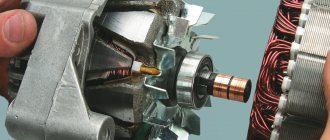
- 7 – generator;
- 8 – horn;
- 9-11 – terminal blocks to the dashboard;
- 12 – contact pair of rear headlights;
- 13 – main radiator fan drive.
"Let's light a cigarette"
This forced start method is very common in the driver's environment. The idea is to temporarily power the starter from the on-board network (battery) of another car.
For successful “lighting”, we acquire cables with the largest cross-section possible. Cars should be placed in friendly positions - with their hoods facing each other. We connect the positive terminals of the batteries of both cars using one wire. We use another cable to connect the negative terminal of someone else’s battery with the ground of the “native” LADA Granta car.
If the startup attempt is unsuccessful, and the car still does not start, we change the circuit. Now we connect the negative terminals of both batteries directly
Be careful to avoid unauthorized short circuits. Having achieved a successful start, do not rush to remove the cables, let the motor run for a few minutes
Remember the disconnection order: remove the negative wire first, and then the positive wire. Do not activate electrical appliances at this time in order to protect them from damage due to a power surge.
Lada Granta diagram - ignition part
- 1 – indicator of lubricant pressure in the crankcase of the power plant;
- 2 – generator connector;
- 3 – power supply to the fuel mixture supply valve;
- 4 – cooling system thermometer;
- 5 – sending a signal to the dashboard;
- 6 – adsorber purge;
- 7 – speedometer;
- 8 – mass air flow sensor;
- 9 – DPKV;
- 10 – DC in front of the catalyst;
- 11 – control pulse device;
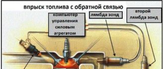
- 12 – oxygen concentration sensor in exhaust gases;
- 13/14 – coil and spark plugs, respectively;
- 15 – injector drivers;
- 16 – ignition contact group;
- 17 – detonation measurement sensor.
Purpose and role of a remote mass switch in the electrical system
Ground switch is a switching device that disconnects the battery from the vehicle ground. This prevents the battery from draining when the car or bus is parked for long periods of time. Also, the mains switch can act as a simple anti-theft device that will prevent the engine from starting, since the switch control button can be hidden.
Today, the most convenient, modern and efficient is the remote mass switch, which has replaced traditional manual switches. A remote type switch is more convenient and has a number of advantages:
• Controlled by one button located in the car interior (bus cabin); • To turn off and turn on the mass, you do not need to open the battery compartment or hood; • Thanks to its hidden installation, it can act as an anti-theft agent.
Remote ground switches have a simple design and principle of operation, therefore they are highly reliable and efficient.
Grant instrument pinout - dashboard diagram
This part is the most difficult. The large number of pins and the miniature size of the terminals greatly complicates the search for the required group:
- 1/2 – connecting blocks for the front electrical harness;
- 3/4 – similar for the feed harness;
- 5 – lighting control unit;
- 6 – ignition switch module;
- 7 – on-board computer;
- 8 – lever for switching the position of the wipers;
- 9 – tidy;
- 10 – control of emergency modes;
- 11 – cargo compartment lid lock;
- 12 – diagnostic connector;
- 13 – block for the air intake drive;
- 14 – button to turn off the heated rear windshield;
- 15 – emergency contact;
- 16 – brake light switch;
- 17/18 – contact group – output to radio equipment (radio tape recorder);
- 19 – rotating equipment module;
- 20/41 – driver/passenger airbag drive;
- 21 – horn power supply;
- 22 – mounting block group;
- 24 – cigarette lighter group;
- 25 – backlight for stove control;
- 26 – interior lamp;
- 27 – contact group of the ignition switch;
- 28 – controller;
- 29 – incoming connector to the rear of the on-board network;
- 30 – electronic part of the gas pedal;
- 31 – additional resistor;
- 32 – stove motor;
- 33 – heater switch block;
- 34 – door lock module;
- 35/36 – cooling system head fan relay;
- 37 – compressor relay wiring;
- 38 – additional relay or reverse indication coil;
- 39 – air conditioner switch button;
- 40 – automatic transmission drive;
- 42 – evaporator thermometer;
- 43 – output to the rear wiring harness.
Progress
So, you purchased a ground switch for a VAZ car. Now it’s just a matter of small things – the connection process. To do this, prepare a workplace and the necessary tools:
Disconnecting the terminal from the battery ground. This will prevent a short circuit, which can cause not only a burnout of the car's electrical system, but even an electric shock. The operation is not difficult, since the terminal wire is painted black and marked with a minus sign.
Disconnection from the positive terminal of the battery. The wire of this terminal is red and marked with a “+” sign.
Disconnection is carried out carefully. At the same time, the level of the electrolyte fluid of the battery is checked and its terminals, both positive and negative, are cleaned with a brush. The ground terminal is retained - it will be needed when the car returns to active use.
Work directly with the switch. This unit is connected to the negative terminal of the battery using a key of the appropriate size. After tightening, you must make sure that the fastening is secure. The wiring terminal, in turn, is connected to the positive terminal of the battery, and the switch is connected to the ground wire.
After the system is assembled, it is tested. This is done with the mains switch turned off (otherwise the fuses will blow). After you are sure that the system is working normally, you can turn on the VM.
Grant ECU pinout
The Lada Granta uses two types of electronic engine control units. Fundamentally, the systems differ slightly, which excludes the possibility of their interchangeability.
| Contact | 11183-1411020-51/52 | 11186-1411020-21/22 |
| A1 | DPKV | |
| A2 | Not involved | |
| A3 | Entering the first knock sensor | |
| A4 | Not used | |
| IN 1 | DPKV | |
| AT 2 | Not involved | |
| AT 3 | Input of the second knock sensor | |
| AT 4 | Main relay output | Not used |
| C1 | Empty | |
| C2 | DTV | |
| C3 | Mass air flow sensor | |
| C4 | UDC | |
| D1 | DDC weight | |
| D2 | Empty | |
| D3 | DTOZH | |
| D4 | Not applicable | |
| E1 | Zeroing the TPS | |
| E2 | Empty | CAN L |
| E3 | Empty | CAN H |
| E4 | Canister purge valve output | |
| F1 | Body from DTV | |
| F2 | Speedometer input | |
| F3 | Not applicable | DFM |
| F4/G4/H4/J4 | Output from injector No. 1/2/3/4 | |
| G1 | Antifreeze temperature sensor ground | |
| G2/G3 | Not used | |
| H1 | On-board electronics grounding | |
| H2 | UDC | |
| H3 | Not involved | Battery charge indicator output |
| J1 | Terminal No. 15 from the ignition switch | empty |
| J2 | Entrance No. 2 TPS | |
| J3 | DDC | |
| K1 | Supplying voltage to the TPS | |
| K2 | Entrance No. 1 TPS | |
| K3 | UDC | |
| K4 | DDK heater power connector | |
| L1/M1 | Leads to the ignition coil ¼ and 2/3 cylinders respectively | |
| L2/M2; L3/M3 | Not involved | |
| L4/M4 | Throttle actuator pin 5/6 | |
The simplest way to check for proper ignition of carburetor VAZ-2109
If there is no spark in the car, you can find the reasons in another way. This technique does not require the use of a special device or tool. In this method, the entire ignition chain is tested, without taking into account the Hall sensor. To carry out this work, we need a small wire with insulated ends and a nail or paper clip.
First of all, we disconnect the high-voltage cable from the distributor. During checking, it must be positioned approximately 10 millimeters from the minus of the car. Next, turn on the ignition. Disconnect the connector from the Hall sensor and connect its end to the middle contact, to which the green wire is connected. We short the other end of our wire several times to ground. At the moment of short circuit, sparks should run between the ground and the end of the wire. If there is a spark in a carburetor VAZ-2109, we can conclude that the Hall sensor is faulty or there is no contact. Often, inside the distributor itself, the plate frays the wires or the connector simply becomes loose. In addition, there are cases when, when checking, we see the presence of a spark, but when connecting the wire to the spark plug caps, there is no spark. This indicates the need to replace the slider inside the distributor. Some carburetor-type VAZ-2109 are equipped with an ignition interlock circuit, which may also become unusable (or there is a malfunction in the switch).
Before performing the test, you need to prepare the following set of tools:
- figured and flat screwdrivers;
- insulated pliers;
- control with a wire or tester;
- spare spark plug.
To protect yourself from electric shock, you should wear dielectric gloves.
Verification process:
- We turn off the ignition, after which we check the high-voltage wires for breaks, and at the same time check for good contact in the connections with the distributor and the ignition coil.
- We carefully inspect the condition of the wires between the distributor and the switch, and also check the wires from the ignition coil to the switch.
- With the ignition switch on on a carburetor VAZ-2109, you need to check the presence of power in the system. To do this, take a test lamp, connect one end to ground, and the other to the “B+” contact of the coil. The glow of the control lamp indicates the presence of power.
- Using a rubber glove, disconnect the middle high-voltage wire from the distributor. We put a spark plug into its tip and touch the engine ground with the metal part. When cranking the starter, sparks should flow from the spark plug.
- Unscrew the screws of the distributor and remove its cover. We check for cracks and damage, and also check the condition of the coal. If the cover is damaged or cracked, it must be replaced.
- We inspect the condition of the slider in the distributor. Quite often it happens when there is no spark due to a breakdown of the interference suppression relay or breakdowns in the housing of the ground slider.
- We check the crankshaft by rotating the starter. If the slider is stationary, the reason for this is a broken timing belt or the drive itself is faulty.
- We check again for the presence of a spark.
- If once again there is no spark in a VAZ-2109 carburetor type car, you should check the high-voltage ignition wiring, as well as the spark plugs themselves. To do this, you must use a known good spark plug. If there is still no spark, change the high-voltage wire.
Grant relay diagram
Relay location in the main mounting block located in the engine compartment:
- 1 – drive of the cooler of the cooling system;
- 2 – central locking protection;
- 3 – secondary starter relay;
- 4 – additional part of the relay;
- 5 – turn signal and emergency signal breaker relay;
- 6 – wiper drive protection;
- 7/9 – insertion of high/low headlight modes;
- 8 – horn protection element;
- 10 – heated aft windshield;
- 11 – main relay block;
- 12 – fuel pump relay.
Pay attention to technological nuances
A good switch is equipped with fuses and serves to de-energize the car battery. It is this circumstance that poses an additional problem for potential hijackers. If you decide to purchase a power switch, make sure it is new. Don't use a used one! In this state, the VM will easily damage the electrical system of the machine.
When the battery is de-energized, there is a high probability that the car computer will turn off. This, in turn, threatens failures, such as erasing from memory information necessary for full operation. How to prevent such a development of events, what energy source to buy and how to connect it - these issues should be discussed with professionals.
Detailed diagram of the VAZ Grant (dashboard)
The vehicle is supplied to the market with a 32-pin instrument panel as standard. The standard pinout of the Grant shield has only 26 pins involved. Residual connectors are provided for the possibility of adding equipment or custom modifications:
- 1 – to the low oil pressure sensor in the engine crankcase;
- 2 – to the handbrake indication switch;
- 3 – intended for service needs when diagnosing the instrument panel;
- 4 – to external lighting switches;
- 5/6 – similar for right and left turn signals, respectively;
- 7/8 – CAN L/H;
- 9 – indication of seat belt position;
- 10 – contact of the Reset button of the steering column lever;
- 11 – response of the brake fluid reservoir sensor;
- 12/13 – on the head optics, high/low beam position;
- 14/15 – foglight terminals front/rear, respectively;
- 16/18 – receiving immobilizer antenna signal;
- 17 – ground wire of the instrument panel;
- 19/21 – to terminal No. 30/15;
- 20 – for the drive of the electric power steering unit;
- 22 – for door closing sensors;
- 23/24 – MK buttons for forward and reverse, respectively;
- 25 – for an environmental thermometer;
- 26 – gas tank float indication.
Where to begin
Before installing the mass switch, you need to select it in accordance with the technical characteristics of the car. This can be done in a specialized organization. Services in this direction are provided by an online store operated by VDS-Torg LLC. The company supplies the market with spare parts for Bogdan, Etalon, Ataman buses, as well as for Tata and Isuzu trucks. Here the interested buyer finds:
- Only certified goods.
- High level of service.
- Individual approach to the client - all his wishes are taken into account, the best options for spare parts are offered based on the price and technical characteristics of the vehicles on which they are planned to be installed.
A reliable mass switch can be found in the Bogdan spare parts catalog, which includes over 1000 items, here is a good model. All components are new, supplied directly from the manufacturer. The price of parts and components in the VDS online store is confirmed with the manager.
Lada Granta: wiring diagram for rear wiring harness devices
The rear part of the car wiring is responsible for the equipment of the stern and sides of the car. all additional equipment is connected exclusively through this part of the highways:
- 1/2 – contact group for the dashboard;
- 3/4 – direction indicators;
- 5 – handbrake indicator;
- 6 – rear window heating contact;
- 7 – interior lamp;
- 8 – indicator of the driver’s seat belt position;
- 9 – cargo compartment illumination lamp;
- 10 – fuel pump drive;
- 11/15 – aft dimensions for the left and right sides;
- 12 – trunk lid lock drive;
- 13 – button for turning on the interior lamp;
- 14 – additional stop chain;
- 16-19 – door terminal blocks for the rear left, rear right, front left and front right doors;
- 20 – airbag control drive;
- 21 – contact group of license plate lights;
- 22 – on the dashboard;
- 23/24 – rear speed indicator sensors;
- 25/26 – seat belt pretensioners;
- 27 – group of dashboard contacts.
Installation of a battery in PAZ buses
All PAZ buses are equipped with an on-board electrical system with an operating voltage of 12 volts (although there are also 24 V modifications). As a current source for the operation of the starter and the electrical system when the engine is stopped, automotive lead-acid batteries of various sizes are used (usually 353 mm long, but large batteries with a length of 513 mm are often used).
The battery is installed in a special battery compartment. On various models of PAZ buses, the battery compartment is usually located in the same place - on the right side of the bus, to the left of the front entrance door. The compartment is closed with a lid that limits access to the battery and prevents tampering.
In PAZ buses, the battery is installed in such a way as to simplify and speed up the process of removing and replacing it as much as possible. This is achieved using a simple mechanism with a slide on which the battery slides out of the compartment. The basis of the device is a metal box open at the top and front, at the bottom of which there are slide guides on both sides. The front wall of the box is made in the form of a folding frame, the side parts of which are a continuation of the guides located at the bottom of the box. When tilted, the frame is held in place by folding metal braces located on both sides of the box.
The battery is installed on a slide, at the bottom of which there are four rollers. The battery is secured to the slide using a clamping frame installed on the top of the battery and four studs stretched between the slide and the clamping frame. The frame is pressed to the battery using wing nuts.
Installation of the battery is carried out as follows: the battery is placed in the slide and fixed with a frame and “wings”; this structure is installed on folded guides, along which it is pushed into the box until it stops. The front of the box with guides lifts up and locks the battery.
The battery connection is made using long flexible cables that extend into the battery compartment. The terminals are installed on the battery before the valve is inserted into the box, which greatly simplifies this procedure.
Here, in the battery compartment, other additional devices can be located. First of all, there is a remote power switch, which ensures that the battery is disconnected from the on-board power supply during long periods of parking.
Preventive measures
In order for the factory wiring of the Lada Grant to serve for a long time and not break, experienced experts strongly recommend following a number of simple rules.
- Periodically check all contact connectors and terminals for oxidation and rust. Such damage to the connections can cause a short circuit and a critical decrease in the conductivity of the line, which is perceived by the on-board computer as an error or breakdown.
- Use only original consumables and electronic components. The use of counterfeit products does not guarantee the functionality of the circuit. At the same time, some elements, when damaged, cause a voltage drop in the network, which becomes a direct cause of failure of other equipment or a fire.
- Use special oil to treat contact groups. The fluid is sold in auto shops or electronics stores. After treatment, the contacts are covered with a moisture-impermeable layer, which increases their service life by 2-3 times.
- Carefully monitor the charge level and condition of the battery. The wiring of the Lada Granta critically perceives a significant voltage drop in the on-board circuits. As a result, this may cause damage to the firmware of electronic control units.
The battery does not charge from the charger
It also happens that the battery does not take charge, and this also becomes a problem, the reasons for which should be found out.
The simplest reason is that the battery is completely discharged and cannot “swing” in low-current charging mode. This happens when the battery has not been used for a long time - for example, it has been lying unused for a long time in a store or warehouse. In this case, you can increase the current and try to restore the discharged battery in a more extreme way. In many cases, this method works, and it, being charged with stronger currents, partially restores its performance.
If you try to charge the battery from a charger that is faulty, the battery will also not respond in any way. Then information on how to repair a charger for a car battery will be useful.
The easiest way is to connect it to another charger and, if the process goes well, it will be clear why the battery is not charging. If the battery does not charge again, it means there is a fault inside it.
In any case, if such a problem occurs during scheduled battery charging, the reason lies either in the chargers or in the batteries themselves
It is important to remember that you should always take care of your car battery and check its condition. During charging, the battery should not be left unattended, especially if there is a need to charge it with high currents, or towards the end of the process, while the electrolyte is boiling.
If there is negligence on the part of the owner, not only “the battery will not charge,” but also an explosion of the battery and poisoning with harmful chemicals may occur. Read about how to properly charge a car battery with a charger here →
As you can see, there are many reasons why a battery may not take a charge. In some cases, the problem can be solved on your own: it all depends on the logic of the driver and his personal skills in the automotive business. Of course, you should always proceed from your real abilities and, if it is impossible to fix the problem yourself, it is better not to take any risky actions, but to seek help from a competent specialist.
“>
Operating the Remote Master Switch
The remote power switch works extremely simply. You can manage it in two ways:
• Using a button in the cabin; • Using the button on the switch itself.
Control from a button in the cabin comes down to the following: to turn the “mass” on and off, you need to briefly press the button. There is no need to hold the button for a long time, since the switch operates quickly, and long-term supply of current to the electromagnet coil leads to its heating and is fraught with damage.
Operating the button on the switch is also simple, however, it requires gaining access to the switch itself. To turn the “mass” on and off, you need to press the button located at the top of the switch. When you turn on the “mass,” you should press the button until it locks, and when you turn it off, you should feel a click of the latch - after which the button can be released and the “mass” will turn off.
The remote ground switch is highly reliable and can serve for many years, preventing premature battery discharge and protecting the bus from theft.
Fuel purification
Electric fuel pump without protective cover
To avoid damage to the fuel pump, it is necessary not only to avoid refueling with low-quality gasoline (use only proven fuel), but also to promptly replace the fuel filter.
Keep in mind that it is not just the fuel filter that prevents contaminants from entering the fuel system.
Impurities can be filtered in the following positions:
- mesh at the inlet to the fuel pump;
- fine filter in the fuel line after the injection pump;
- mesh in front of the fuel pressure regulator;
- mesh in front of the fuel injector entrance.
The first two positions directly affect the correct operation of the pump. The frequency of replacing the fuel filter is determined at 30 thousand km, but owners do it more often, given the low-quality spilled gasoline.
The frequency of replacing the fuel pump grid for rough cleaning Kalina is not determined at the factory and for this reason it is forgotten until a situation arises when the fuel pump begins to fail.
In this case, it is recommended to clean the mesh and, if necessary, for example, if it is damaged, replace the fuel pump mesh. It is advisable to carry out this replacement every 50-60 thousand km.
Cleaning the fuel pump dirt collection screen
What else is important when choosing a battery for Kalina
It is important to remember that the battery for Kalina (whether it is a station wagon model or another modification) is relatively small. Therefore, batteries with a large capacity can not be considered - it won’t take much energy to spin up the engine. Unless, of course, your plans include “stuffing” your car with all sorts of electronics. If this is still planned in the future, you will have to think about an option with a large capacity.
When it comes to battery capacity, it is generally better to avoid extremes. You should not buy a battery with very impressive capacitance indicators. But at the same time, it is not recommended to purchase a unit that is too small in capacity. After all, in this case it will be far from powerful.
It is recommended to choose the most optimal one. For example, a system with a capacity of 65 A/h. A device with such characteristics will cope well with energy accumulation and will produce normal power. And it will not fail in difficult situations.
No less important is the inrush current. In the case of Kalina, it is better if it is equal to 425 A. This will ensure stable operation of the battery.
Now regarding the material from which the battery should be made. The best option for the Viburnum Lada is a lead-acid device. Other types are best left for other cars.
Replacing the fuel pump Kalina
Before replacement, read the owner's manual to determine the location of the fuel system component, the characteristics of adjacent fuel lines, and the types of fasteners. When working, it is important to follow the specified algorithm so as not to disrupt the operation of the fuel system. A damaged fuel line or improperly installed fuel module can damage the engine and even cause a vehicle fire.
To carry out the work, the car owner will need:
- pliers;
- hammer;
- screwdrivers, flat and Phillips.
Sequence of replacing the fuel pump Lada Kalina
Before starting work, it is necessary to “de-energize” the Kalina by removing the battery terminals. Repair work must be carried out away from fire and sparks.
- Remove the rear seat and floor covering;
- The fuel tank cap is located under the seat and is secured with 4 Phillips bolts. Unscrew;
- The car owner now has access to the top cover of the fuel pump;
- Now you need to “disconnect” all plugs and fittings from the pump. To remove the plug from the outlet, press the latch and pull the plug to the side. The power plug itself is located on the left side of the fuel pump cover;
- To remove the fittings you need to use pliers. The locking latch is compressed manually, after which the fitting itself is removed with pliers. The main thing is not to confuse the fittings: on the top it is green, on the bottom it is metal;
- Having disassembled the fittings, we clean the fuel pump cover as much as possible - dirt will not get into the gas tank;
- Disassembling the fuel pump cover retaining ring: Take a flathead screwdriver, place it on the outline of the ring and lightly tap with a hammer so that the ring moves clockwise. The latch should come out: the cover will be accessible;
- Open the lid and carefully pull out the pump so as not to damage adjacent elements. In addition, we make sure that sand does not get into the container;
- We take a new pump and carefully dip it into the technological hole. Attach the lid. Further assembly is carried out in reverse order.
After the repair, you need to start the Kalina and drive for a few minutes. During operation, it is necessary to check the operation of the internal combustion engine in different speed ranges, at idle speed; You should also beware of various noises in the fuel tank.
Source of the article: https://prodemio.ru/massa-benzonasosa-kalina-gde-nahoditsja/
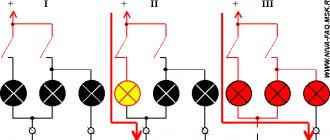
Where is the engine ground attached? Why is the engine unstable?
In almost 100% of modern cars, the body is used as a single source of electrical energy. The car body is like a universal wire with a negative charge for all consumers of electricity. That is why the body is called the painfully familiar term “mass”. Why “painfully familiar”? Yes, because if somewhere the contact with the mass is either poorly secured or oxidized, the inexplicable begins. Let’s take the first example we come across: the sore subject of the first and second Samaras is the blinking of yellow and red headlights, etc. I have already analyzed this situation in the article: why the headlights do not light up, where I made a “mass”, as the main reason for unstable operation. But the headlights are a small thing compared to the performance of the engine and the electronic engine control system (ECS). In this article we will look at the weak “mass” points on the VAZ 2114 2113 2115 with 1.5l, 1.6l engines.
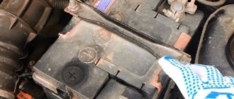
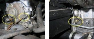
Battery weight
The “minus” on the battery has two branches: a thick wire and a thin one. A thick wire runs from the battery negative to the engine housing. If this contact is not secured properly, then the battery is not fully charged, the starter does not develop full power, and the ECM stalls (since it takes weight from the engine).
On the negative mount of the battery with the engine, you need to check the tightness of the two nuts between which the contact to the engine is attached: first of all, loosen the outer nut and tighten the inner one, and then tighten the outer one.
The second wire from the battery is much thinner and is attached to the body next to the battery itself. This wire is the source for all energy consumers in the car. Here you also need to check the tightening torque of the nut both to the body and to the battery terminal.
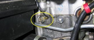
ECM weight
For SAMAR with a 1.5 liter engine, the mass for the ECM is taken from the engine housing, from the fastening of the plugs. The plugs are located on the right side of the block head.
For SAMAR with a 1.6 liter engine, but also 1.5 liter engines, which have a new generation ECM (Bosch 7.9.7, January 7.2), the weight of the ECM is taken from a welded stud. The pin is attached to the metal frame of the instrument panel to the floor tunnel (under the ashtray). In practice, it happens that this pin is painted at the factory and is loosely tightened. Therefore, over time it may become loose and at the moment the fan is turned on, there will be a drop in the voltage of the following sensors (which will lead to jumps in speed): DTOZH, TPS, MAF.
Connections of the torpedo harness, mounting relay and fuse block diagrams, rear harness
Weight of torpedo (instrument panel)
At this point in the bundle there are connections of the torpedo harness, circuit diagrams of the mounting relay and fuses, and the rear harness. This connection is located under the steering shaft mount. If this connection is unreliable, then deviations in the instrument panel readings are possible when energy consumers (headlights, turn signals, etc.) are turned on.
Heater motor weight
This ground connection is located under the instrument panel on the left side of the heater housing.
In conclusion, it is worth noting that absolutely all factory-made studs are not treated in any way other than paint, so over time, corrosion, oxidation appears, and voltage drops begin.