I decided to check the charging during the week! He came home from work, I connected the tester to the battery terminals. At XX, warmed up: 13.72V; at XX with consumers turned on, which he often uses in winter (dimensions with a neighbor, stove on 1st, heated rear window and mirrors, radio): 12.6V. Those. in the first case it is low, and in the second it is too much.
I tightened the alternator belt, and at the same time I thought, let me take on: the ground on the power steering reservoir bracket:
weight on the engine:
ground from the “-” terminal of the battery to the body:
ground from the “-” terminal of the battery to the engine:
I didn’t touch the other masses, there’s no need and no point!
All these masses and their studs were cleaned of the slightest dirt, cleaned if necessary, lubricated and well tightened. Before this, I did not forget to remove the terminals from the battery, wiped the entire battery, cleaned and lubricated the terminals, also removed the wires hanging on them and also cleaned and stripped if necessary and lubricated, everything was tightened well! There was no result, and there was no time to mess around!
I came to the dacha over the weekend and decided to finish it. I removed the “-” terminal from the battery. pulled out and inserted two generator power circuit fuses F4, F6 (60 A), in the main fuse block:
weight was transferred from the engine (thermostat) to the gearbox stud: from here: here (at the very bottom in the photo):
Result: At idle, warmed up: 13.85V; at XX with the consumers turned on, which he often uses in winter (dimensions with the neighbor, stove on the 1st, heated rear window and mirrors, radio): 13.1V.
If he and I had time, I would borrow a friend’s garage and modernize the gene like mine, installing the RN no. . Everything is great for me, although I haven’t written a report since January 8th of this year, apparently a year will have to pass)))))))))
Source
How to check the ground on a Priora engine
Prior's father has a sedan from the end of 2009, 1.6l 16kl engine, mileage 42,200 km.
The configuration with power steering for that year is the simplest, one might say, if you don’t count the Prior with an 8kL engine. I decided to check the charging during the week! He came home from work, I connected the tester to the battery terminals. At XX, warmed up: 13.72V; at XX with consumers turned on, which he often uses in winter (dimensions with a neighbor, stove on 1st, heated rear window and mirrors, radio): 12.6V. Those. in the first case it is low, and in the second it is too much.
I tightened the alternator belt, and at the same time I thought, let me take on: the ground on the power steering reservoir bracket:
weight on the engine:
ground from the “-” terminal of the battery to the body: ground from the “-” terminal of the battery to the engine:
I didn’t touch the other masses, there’s no need and no point!
All these masses and their studs were cleaned of the slightest dirt, cleaned if necessary, lubricated and well tightened. Before this, I did not forget to remove the terminals from the battery, wiped the entire battery, cleaned and lubricated the terminals, also removed the wires hanging on them and also cleaned and stripped if necessary and lubricated, everything was tightened well! There was no result, and there was no time to mess around!
I came to the dacha over the weekend and decided to finish it. I removed the “-” terminal from the battery. pulled out and inserted two generator power circuit fuses F4, F6 (60 A), in the main fuse block:
weight was transferred from the engine (thermostat) to the gearbox stud: from here: here (at the very bottom in the photo):
Result: At idle, warmed up: 13.85V; at XX with the consumers turned on, which he often uses in winter (dimensions with the neighbor, stove on the 1st, heated rear window and mirrors, radio): 13.1V.
Source
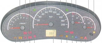
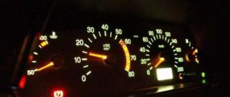
Dashboard indicator symbols
| 1 | Tachometer. The device measures the engine crankshaft frequency (revolutions per minute). If the arrow goes beyond the red value, it means that the Lada Priora engine is operating in a dangerous mode; |
| 2 | Brake force distributor indicator. Reports defects in the operation of this node; |
| 3 | Battery charge. If the lamp lights up while the engine is running, the battery is discharged; |
| 4 | Left turn signal. The sign flashes when there is an alarm or the left indicator is on; |
| 5 | Speedometer. The device reports the speed at which your Lada Priora is currently moving; |
| 6 | Emergency lubricant pressure in the engine. If the sign lights up during operation of the power plant, it means the pressure in the system is low; it is highly not recommended to operate the engine in this condition; |
| 7 | Right turn signal (see No. 4); |
| 8 | Handbrake indicator. Lights up yellow if the Lada Priora is in the handbrake; |
| 9 | Antifreeze temperature in the cooling system. The operating temperature of the motor starts from 90° and above to the red mark. If overheating occurs, turn off the engine; |
| 10 | Gasoline level in the tank. If the fuel level approaches the minimum, the fuel pump may break; |
| 11 | Reserve gasoline level. The indicator lights up when there are less than 10 liters left; |
| 12 | Key for resetting the daily mileage and switching between display modes; |
| 13 | Alarm. If you have triggered the emergency lights, the lamp will flash along with the turn signal arrows; |
| 14 | Malfunctions in the electric amplifier. If defects appear in the EUR, the lamp will light up while the engine is running; |
| 15 | High beam designation. An active indicator indicates that you have switched to distant; |
| 16 | Outdoor Lighting. The system notifies the driver about the operation of the headlights or low beams; |
| 17 | Airbag malfunctions. If the lamp lights up after starting, then there is a high probability that the airbags will not deploy in a collision; |
| 18 | Immobilizer. An audible signal and flashing indicate that the immobilizer system is faulty; |
| 19 | Computer screen. Here you can view information from the bookmaker, as well as find out the total and daily mileage; |
| 20 | Indication of unfastened seat belts. The buzzer will signal a violation for 90 seconds; |
| 21 | The brake system is in disrepair. Most often these are worn pads or insufficient fluid in the system; |
| 22 | Disabling a specific airbag; |
| 23 | Indicator of defects in ASB operation, the braking system is operating normally; |
| 24 | Check Engine – there is a breakdown in the engines; diagnostics and subsequent repairs are urgently required. |
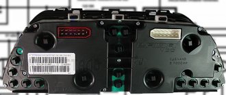
Removing the instrument panel
We carry out work to replace the instrument panel, panel wiring harness and elements of the heating and ventilation system. Disconnect the wire terminal from the negative terminal of the battery. We remove the steering column switches (see “Removing the steering column switches, switch connector and spiral cable drum device”). Remove the cover of the fuse box (see “Replacing fuses and relays”). We disconnect the wire blocks from the ignition switch (see “Removing the ignition switch, replacing the contact group and immobilizer coil”). We disconnect the wire blocks from the electric power steering control unit (see “Removing the steering column”). Remove the floor tunnel lining (see “Removing the floor tunnel lining”). Overcoming the resistance of plastic latches...
...remove the left front pillar trim. Similarly, remove the upholstery of the right front pillar.
Using the blade of a slotted screwdriver, placing soft material under it, pry off the glass blower nozzle of the left door. Similarly, remove the blower nozzle on the right side.
Using a 10mm socket, unscrew the nut for the upper fastening of the instrument panel, located in the cavity under the door glass blower nozzle. Similarly, unscrew the nut on the right side.
Using a 10mm socket, unscrew the bolt securing the ground wire ends of the instrument panel.
We disconnect the wiring harness connectors of the instrument panel from the wiring harness connectors located on the bracket above the fuse mounting block...
...and the wire block located on the right end of the bracket.
Disconnect the engine control wiring harness block from the instrument panel wiring harness block...
...and use a 10mm head to unscrew the nut securing the end of the ground wire. We disconnect the middle block of the instrument panel wiring harness from the electrical accessories control unit (see “Removing the electrical accessories remote control system controller”).
Description of the dashboard
The dashboard contains the following elements:
- Unit for controlling instrument lighting and external lighting.
- Horn switch.
- Switch for turn signals and headlights.
- Instrument cluster for Lada Priora.
- Lever for glass washer and wiper.
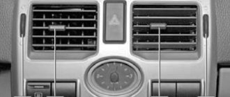
There is also an ignition switch on the instrument panel, which is combined with an anti-theft device. On the Lada Priora it has three positions. In addition, the instrument panel contains buttons and mechanisms such as a heated switch on the rear window, a clock, an alarm switch, a glove box lid, a tape recorder socket, an ashtray, a fan control unit, etc.
Tuning for the dashboard (dashboard) can be done with your own hands if you want to change the lighting for the instruments. In this case, the panel must be removed. The answer to the question: “How to remove the panel?” quite simple - using a screwdriver. Then we unscrew the fastening screws, disassemble the panel, remove the hands (you can use a knife, placing a piece of cardboard on the dial), and separate the cover from the plexiglass.
Replacing the dashboard backlight is done by scraping off (with a knife) the coating on the gasket numbers. If you want to leave them white (brighter), then you can put all the elements back together. However, many drivers want to make the instrument panel more informative. To do this, take a not very thick plastic bag with colored designs, from which parts of a certain color are cut out and glued to the back of the instrument panel. This way you can highlight, for example, areas of high speed on the speedometer, or “cold” areas on the temperature scale.
ECU weight
How the mass of the ECU works, how to check the mass of the ECU, what problems may arise and how to modify it to avoid troubles in the future.
It is these very important questions that we will address on this page.
A reliable ECU ground is very important for the proper operation of the engine management system and the engine as a whole.
It would seem to be a primitive and reliable design that can serve well for years. But in reality this is far from the case.
It is very difficult to list all the possible problems that can arise due to poor ECU mass, since it can affect anything. But the main problems can be divided into two points:
The exclamation mark is on - what to do?
We have noticed that new topics often appear on car forums where drivers ask about the exclamation marks that are displayed on the Lada Priora panel. They rarely specify where it is lit and what is depicted on the icon. In this section we have collected a small FAQ Below are all the exclamation marks that can light up on the instrument panel of a VAZ 2170 car. The designations of these icons are as follows:
The red exclamation mark in the circle (bottom) is lit. The indicator indicates that there is a problem with the vehicle's brake system. This is usually a low brake fluid level. Add it to the tank and, most likely, the sign will stop lighting. If this does not happen, then it is worth checking the system for damaged components. When igniting, the indicator lights up for 4 seconds and then goes out. The red exclamation mark in the triangle/circle (above) is lit. Modern versions use a triangle instead of a circle. The indicator tells us about defects in the operation of the brake force distributor
Use extreme caution if the light comes on while driving. Exclamation mark near the steering wheel icon
When illuminated for a long time, it indicates a malfunction in the electric power steering (EPS). Like other icons, it lights up when ignited and goes out after a few seconds if the system is working properly.
Where is the ECU ground located?
The ECU mass is usually arranged like this. The engine control unit housing itself is screwed to a metal bracket, which, in turn, is screwed to the car body. Also, a separate ground wire is removed from the ECU connector, which is connected to the engine via the starter mounting bolt.
Everything is simple and reliable. But in reality, over time, the voltage begins to drop in this section of the circuit, slowly but surely, disrupting the operation of the system.
This article is a logical continuation of the previous article, where we checked the voltage drop in the ground circuit from the engine to the body. I advise you to familiarize yourself with it first, and then continue to implement the modification given below in this article.
In general, last time we found a voltage drop in the ground circuit from the engine to the ECU
And on this page we will solve this problem by laying additional mass from the ECU to the engine and from the generator to the body.
We will look at the mass from the generator in another article very soon (I’ll give a link here), and on this page we will focus on the additional mass of the ECU.
What could happen to the car due to poor ground contact?
With the electrical equipment of any vehicle, malfunctions can occur that seem to people far from electricians to be the work of evil spirits. And the culprit of mysterious malfunctions in the electrical equipment of a motorcycle or car, in most cases, is poor contact of the negative terminals - “ground”. But let's take things in order.
Many drivers know that the method of connecting electricity consumers to a power source (generator or battery) on any vehicle is single-wire. The second (negative) wire is the body of a car or the frame of a motorcycle (trike, scooter, ATV, etc.). The very idea of connecting the negative side of a power source (battery) to a steel frame or body is quite old and natural, as it can significantly simplify, lighten and reduce the cost of any vehicle.
A separate ground wire is used to connect the engine to the body or frame, since the engine hangs on rubber mounts that do not allow current to pass through, while both plus and minus are required by the starter, and, for example, by the carburetor solenoid valve. On foreign cars, especially injection ones, there may be even more consumers requiring electricity (and, accordingly, plus and minus). But the positive wires usually begin and end with quite reliable terminals, which are usually in completely sealed plastic blocks or rubber covers, but the negative wires are attached to the body or frame according to the principle “some water will find a hole.” And the body itself, in the place where the hole is drilled and the negative wire is secured, begins to rust very quickly, unless, of course, appropriate measures are taken immediately.
In addition, many do not take into account another important fact, which is known even to a novice electrician: aluminum and copper terminals cannot be connected to each other, since these metals, to put it mildly, are “not friendly” with each other, and begin to oxidize intensively. How can oxidized parts have normal contact? But I often see on the vehicles of inexperienced drivers, on the aluminum housing of the gearbox or engine head, a screwed-on copper terminal of the negative wire, which, in addition, is also washed by streams of water in bad weather.
A steel body or frame is also not friendly with copper, like aluminum, and forms an electrochemical couple. And the saddest thing about this is that the steel in such a connection will be blown away by two people and will corrode several times faster. As a result, the contact disappears (or there is a significant loss of current). Standard terminals installed at the factory are usually tinned. But under a thin layer of tin, which is easy to tear off when installing the terminal, there is still the same copper alloy.
Based on the above, it is obvious that the negative connections themselves to the body or frame are initially less reliable than the copper wires themselves and their copper terminals (tips). Now imagine, for example, in order for electricity to reach the carburetor solenoid valve, the electric current must go along a copper wire (copper bus) from the battery to the body, then along another wire to the engine, then along the intake manifold studs and their threads, often coated with sealant (or the studs are rusty), and finally go along the threads of the solenoid valve itself. Loss of contact in any of the listed places - and the circuit is open, and hence a whole bunch of malfunctions. As a result, the inexperienced driver is surprised - why did the carburetor suddenly begin to work poorly and gasoline consumption increase? You need to go to a carburetor specialist or buy another carburetor. But usually few people know that in such a situation the carburetor has nothing to do with it. And I gave one example of a sudden malfunction, but there can be many of them.
Therefore, in modern cars or motorcycles, full-fledged negative wires are increasingly used, because modern on-board electronics will not work without them, and most devices or programs will fail. On such equipment, reliable contact is especially important. Experienced electricians know, and I have already said this: in electrics there are only two faults - there is a contact where it is not needed, and there is no contact where it is needed.
Typical malfunctions on a car due to poor ground contact (but not all, we read about the rest below) .
These malfunctions, as I already said, seem like miracles to inexperienced drivers. It is not uncommon at a factory (especially a domestic one) to place the negative terminal of the headlight on a stud or bolt securing the headlight housing to the body, and then tighten it with a nut. At first glance, many will think that everything is correct, because the stud or fastening bolt is welded to the body. But the headlight housing is made of soft plastic, and the nut on the terminal cannot be tightened properly, otherwise the plastic will crack. In the end, it only takes a short drive on our roads to weaken such contact to the point of its complete absence. But in a standard headlight with a modest lamp of 55-60 watts, the current consumed even by such a lamp is quite large - up to 10 amperes (if both its threads are energized, both high and low beam).
In the end, a bad contact, if it does not disappear completely, will burn out, the resistance of such a connection will increase even more, and from a school physics course we know that the greater the resistance, the more heat is released when current passes in this place. This means that the burning of contacts will intensify even more (a vicious circle), and it’s not far from a fire (plastic burns well). And many young novice drivers, instead of a standard 50-60 watt lamp, install a hundred (100 watt), which consumes even more current. The consequences can be dire.
Additional ECU weight
We will try to do this within the budget. Therefore, I immediately want to dissuade you from adding additional mass to the ECU using special wires for mass and all kinds of copper braids. And I see three reasons for this:
Therefore, I think that the ideal option is a regular wire with a cross-section of approximately 4 sq. mm. Actually, this is the path I followed.
Using the example of a Chevrolet Lacetti with a Sirius D42 control unit, we will need:
The whole thing cost 30 UAH.
Disconnect the negative terminal of the battery
Now you need to use a 12 mm wrench to unscrew the nut securing the negative wires to the starter bolt
This is not as difficult to do as many people think. Yes, everything needs to be done by touch, but it is quite possible. I have unscrewed this nut a huge number of times, so I can do it in one minute without any problems. Believe me, the eyes are afraid, but the hands do! Or rather, in our case, the eyes don’t see, but the hands do
We lean towards the engine from the battery side, extend our hand to the starter, feel for the nut under which the wires are located, loosen it with a wrench, and then unscrew it with your fingers
Remove the nut, then the engraver and take out the wires towards you
We clean them and add our additional ground wire to them
Where are the “mass” points on the body?
The main points of “mass” on Vesta are located in the engine compartment, as well as in the car interior behind the panel (dashboard):
Other ground attachment points:
We will add other places where the mass is attached as we study Vesta.
How to maintain vehicle ground points
Poor contact will affect the operation of electrical appliances. Most often these are large-scale failures or “glitches” of the vehicle’s electrical equipment. To prevent this, you should monitor the condition of the mass attachment points:
Have you ever encountered problems with your car's electrical system when the cause was a bad ground? Let us remind you that other operating instructions for Vesta can be found in this category or in the contents.
I decided to check all the masses, clean the connections and duplicate + and - to the battery. Let's start with something interesting - Cleansing the masses. I found only 4. We also find them, take sandpaper 200 - 400 and go:
— The first and most important one is located near the battery, behind the headlight. The backup KG-35 was attached there. — The second one is on the head near the air vent — The third one is behind the left headlight — The fourth one is on the ECU mounting bracket
Cleaned everything up and tightened it securely.
The duplicate KG-35 goes from the gene to the battery (+) and from the body to the battery (-) This did not fix the problem with the sensor (I will calibrate it tomorrow) But the voltage has increased, engine starting has become faster and... it seems that the car drove a little more fun
Engine demining and signs of poor grounding
An electrical circuit needs a good ground to function properly. Many people ask - why is engine demining necessary? The answer is - poor electrical grounding can affect one or more electrical systems, because it forces the current to look for other simpler paths. This can cause all sorts of problems with lights, sensors, modules and other electrical and electronic components, all of the above is also true to answer the common question - what is the purpose of mass in a car.