Bright corner - LEDs • Interior lamps in Lada Priora
Let's shine a light on our favorite pepelats
Interior lamps in Lada Priora
RZ296 » Aug 28, 2011, 00:02
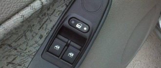
The car is a Lada Priora in the Lux configuration - two LED lamps, in the front there are two spot lights with 12 mm LEDs and one common with 3 piranhas, in the back there are only 2 spot lights. The spectrum, it should be noted, was neutral, without noticeable blue. The diodes worked in, presumably, prohibitive modes - 30 mA for the point ones and it’s unclear how much for the piranhas (two 33 Ohm resistors, it’s unclear what the drop on the diodes is, I didn’t measure it. First one of the piranhas died - the lamp blinked. Temporarily installed 4 segments LED strip on warm white diodes. Then, with a difference of 2 weeks, both rear diodes blinked. I ordered 3HP2C, removed the shades and began to remodel. From the dealextrimov ceiling lamp with 7 one-watts, embedded in a table lamp with the dismantling of the optics, 7 collimators with a diameter of 20 mm remained. I really didn’t want to glue the collimators with the front plane, but there was no other option, so I did the following: I ground off the tubes of the lamp housing protruding inward at an angle (the original diodes stood at an angle on plastic stands on the boards). In the photo, the left one has already been sawed off. I mounted 3 on the boards radiator made of AMCP sheet 2 mm thick: On the boards, the lead-out elements in the radiator area were raised above the boards so that the leads did not reach the back surface of the board. I glued the diodes onto the radiators with hot glue - one for the spot ones and 2 for the central ones (I also decided to add a central light at the back): I replaced the quenching resistors - with 2 point resistors connected in series with 47 Ohms each, and with central ones - two in parallel with 100 Ohms. The current through the diodes is about 100 mA, you don’t need much more, and there won’t be any problems due to the small area of the radiators. I did not install stabilizers due to the fact that smooth attenuation of light is implemented as standard, and with such a current reserve they are not needed. Installation using conventional MGTF. On the boards near the elements there is not flux, but remnants of the urethane varnish that was used to coat the board at the factory. A disgusting substance in terms of repair. I connected the rear light to the battery from a screwdriver and locked myself in the bathroom with it: I was happy to note that gluing the collimators to the body had virtually no effect on focusing. Now how it shines in the car: The result is excellent, nothing could be asked for better. The last photo shows an example of how the front passenger's spotlight shines. The footwells of the driver and front passenger are illuminated using strips of warm white diodes, switched on in parallel with the corresponding spotlights. RZ296 Flashlight Messages: 26 Registered: Aug 14, 2011, 07:32 pm From: Moscow region, Klimovsk Thanked: 0 times. Thanked: 3 times.
Delivery by Russian Post (cash on delivery, no prepayment)
Lada Granta instrument panel pinout
Advantages: the most widespread network in Russia, delivers to any corner of the country, including remote ones. Flaws:
- high cost of delivery of heavy or large parcels, as well as the weight of one parcel should not exceed 20 kg;
- long delivery times and queues in large cities for receipt.
To send your order by Russian Post:
Delivery time may vary depending on how far your locality is from Togliatti and usually ranges from 5 to 14 days.
The cost of delivery is calculated based on the volume, weight of the selected product and the distance to the recipient's settlement.
Required for sending:
- indicate full name recipient;
- Your mailing address;
- Your phone number (contact);
- Post office code.
Russian Post commission for cash on delivery service:
- purchase price up to 1,000 rubles. – 70 rubles + 5% of the amount;
- purchase price from 1,000 to 5,000 rubles. – 80 rubles + 4% of the amount;
- purchase price from 5,000 to 20,000 rubles. – 180 rubles + 2% of the amount;
- purchase price from 20,000 to 500,000 rubles. – 280 rubles + 1.5% of the amount.
Russian Post - Delivery of goods up to 20 kg throughout Russia. https://www.pochta.ru
Delivery time and cost Track the parcel Calculate delivery by mail
Wiring diagram for a VAZ 2114 car
Electrical wiring components
Lada largus fuse box A single-wire circuit (used for all electrical wiring) has negative consumer and source terminals, which are connected to the car body. The VAZ 2114 body is the second connector.
Complete circuit with electronics in VAZ 2114
Electrical wiring includes the following components:
- Block headlight.
- Anti-fog headlight.
- Temperature indicator.
- Mounting block housing.
- Electric fan motor in the engine cooling system.
- A block connected to the ignition system wiring group.
- Engine compartment light switch.
- Rear wiper motor connector plug.
- Devices.
- Car signal connection block.
- Electric motor for windshield wipers.
- Loudspeaker signaling device (SSU) housing.
- An indicator showing the volume of water in the glass washer.
- Front brake pad mode indicator.
- Oil quantity indicator.
- Generator and starter housing.
- Reversing headlight switching device.
- Lubricant pressure warning light indicator.
- Windshield wiper gear motor housing.
- Light housing under the hood.
- Engine coolant temperature indicator. 2x h16
Circuit breakers
In fact, the VAZ 2114 wiring is always connected to fuses. Such fuses do not protect only the circuit of the generator and charging device, the mechanism for switching on the power unit of the machine, as well as the winding of the backlight cut-off relay.
Before replacing a failed electrical circuit fuse, you need to find out exactly the reasons for the wiring overload, as well as its elimination. Finding the cause will be much easier if you first read the following materials. Below is a list of fuses and their purposes.
The data (the name of the fuse and the electrical circuit protected by it) shows a complete list of all possible wiring fuses. For each car, their number may differ.
- F1. Wiring diagram for the rear fog lights, electric motors for the headlight wipers, housing for the control lamp and its shutdown, electric motor for the headlight cleaner.
- F2. Turn signals and turn signal relays, hazard warning lights, hazard lights.
- F3. The wiring of the lamp illuminating the interior is customized depending on the personal preferences of the car owner, the ignition switch light, the car trunk light, the engine functionality check indicator, the on-board computer, the brake light indicator, and the clock.
- F4. A plug for connecting a portable lamp, a plug that connects the heating of the stern and rear windows.
- F5. Connection diagram for SGU, radiator propeller electric motor, VIP signal relay.
- F6. Power window relay, power window connection circuit. Fuse box in VAZ 2114
- F7. Wiring of the electric motor of the VAZ 2114 stove, electric motors for the headlight wipers and windshield washer, cigarette lighter circuit that illuminates the glove compartment, light bulb, relay for connecting the aft glazing heater winding.
- F8. Wiring diagram for the right fog lamp.
- F9. Left fog lamp diagram.
- F10. Electrical wiring for the side lights on the left side, an indicator that shows whether the side lights are on, a circuit for the engine compartment lamp, illumination of license plates, heating system levers and ashtrays, a cigarette lighter, a circuit for illuminating the switches.
- F11. Side lights located on the left side.
- F12. Right low beam design.
- F13. Left low beam design.
- F14. High beam device and left bulb. It is also an indicator for switching to high beam.
- F15. Right high beam design.
- F16. Wiring of turn signals, hazard light relay, relay responsible for the state of the lamps in the headlights, rear traffic indicator, lights signaling the following: low oil and brake fluid levels, whether the parking brake is on, low battery charge. Also a clock, an on-board computer and a generator excitation winding circuit during the start of the power unit of a VAZ 2114 car.
In addition to all the fuses listed above, which are located in the mounting block, there are 3 fuses. These fuses are located under the magazine shelf. The controller and relay circuit are also located here, with the help of which the VAZ 2114 power unit is controlled.
Blog about UAZ
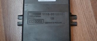
Lighting control modules MUS 50.3769, 521.3769, 522.3769, 58.3769, 582.3769 are designed for switching electronic control circuits for external lighting, front and rear fog lights, adjusting the level of illumination of controls and devices, and controlling the angle of the light beam of auto headlights.
Lighting control module MUS 50.3769 for Lada Granta, VAZ-2190, Lada Kalina FL, VAZ-2192, VAZ-2194, properties, purpose of contacts.
Connecting the lighting control module MUS 50.3769 to the electrical equipment system of Lada Granta and Lada Kalina FL is done using block 1118-3724500.
The main properties of the lighting control module MUS 50.3769 for Lada Granta, VAZ-2190, Lada Kalina FL, VAZ-2192, VAZ-2194.
Rated voltage, V: 12 Rated overload: — Inductive: 110 mH; 0.5 A contact 56, 50 mH; 0.25 A contact 1 - Lamp: 10 A contact 58 and contact 3, 5A contact 4, 2.5 A contact 2 Color of the viewing surface: dark Color of signs: snow-white Color of backlighting of signs: green Dimensions, mm: 70x110x64 Weight, not the most , kg: 0.2
Numbering and purpose of contacts of the lighting control module MUS 50.3769 for Lada Granta, VAZ-2190, Lada Kalina FL, VAZ-2192, VAZ-2194.
G - not used. 56b - not used. 58b - not used. 31 - Mass. Xz - +12 Volts from terminal “15” of the ignition switch. 56 - to low beam lamps. 1 - Ground (signal for turning on side lights from the central body electronics unit) (only for MUS 50.3769-01). 2 - to the rear fog lights. 3 - to the front fog lights (only for MUS 50.3769-01, -02). 4 - to daytime running lights. 58 - to side lamps and device illumination sources. 30 - +12 Volts from terminal “30” of the ignition switch.
Lighting control modules MUS 521.3769, 522.3769 for Lada Priora, VAZ-2170, properties, purpose of contacts.
Connection of lighting control modules MUS 521.3769, 522.3769 to the Lada Priora electrical system is done using block 1118-3724500.
The main properties of lighting control modules MUS 521.3769, 522.3769 for Lada Priora, VAZ-2170.
Rated voltage, V: 12 Rated overload: - Active: 2 mA contact G - Capacitive, not less than 0.1 µF: 1-16 mA contact 2 (PTF), 1-40 mA contact 2 (ZPTF), 1-16 mA pin 4 (“+” brightness), 1-40 mA pin 4 (“-” brightness), overload is switched to pin 31 - Lamp: 10 A pin 56 and pin 58 Viewing surface color: dark Sign color: snow-white Sign backlight color: green Indicator backlight color: ZPTF - yellowish, PTF - green Dimensions, mm: 155x73x60 Weight, not more than, kg: 0.25
Numbering and purpose of contacts of lighting control modules MUS 521.3769, 522.3769 for Lada Priora, VAZ-2170.
G, 56b - to the gearmotor of the headlight range control. 58b - from illumination sources of controls and devices. 31 - Mass. Xz - +12 Volts from terminal “15” of the ignition switch. 56 - to the headlight low/high beam switch. 1 - from the rear fog lights. 2 - to the controller (turning on the rear/front fog lights). 3 - from front fog lights (only for MUS 522.3769). 4 - to the controller (adjusting the backlight level of devices). 58 - to side lamps. 30 - +12 Volts from terminal “30” of the ignition switch.
Lighting control modules MUS 58.3769, 582.3769 for Lada Priora FL, VAZ-2172, properties, purpose of contacts.
Connection of lighting control modules MUS 58.3769, 582.3769 to the electrical equipment system of Lada Priora FL is done using block 1118-3724500.
The main properties of lighting control modules MUS 58.3769, 582.3769 for Lada Priora FL, VAZ-2172.
Rated voltage, V: 12 Rated overload: - Active: 2 mA pin G, 0.0005-0.05 A pin 56b - Inductive: 0.25 A pin 2 and pin 4 - Tube: 10 A pin 56, 5 A pin 58, 2.5 A contact 58b Color of viewing surface: dark Color of signs: snow-white Color of illumination of signs: green Color of illumination of signaling devices: ZPTF - yellowish, PTF - greenish Dimensions, mm: 155x73x60 Weight, not more than, kg: 0.25
Numbering and purpose of contacts of lighting control modules MUS 58.3769, 582.3769 for Lada Priora FL, VAZ-2172.
G - to the gearmotor of the headlight range control. 56b - to the controller of the automatic lighting control system (only for MUS 582.3769). 58b - to sources of illumination of controls and devices. 31 - Mass. Xz - +12 Volts from terminal “15” of the ignition switch. 56 - to the headlight low/high beam switch. 1 - from the rear fog lights. 2 - to the rear fog lamp relay. 3 - from front fog lights (only for MUS 582.3769). 4 - to the front fog lamp relay (only for MUS 582.3769). 58 - to side lamps. 30 - +12 Volts from terminal “30” of the ignition switch.
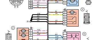
Pinout of the instrument panel VAZ 2170 Priora
The layout of the instrument panel is made in a simplified version to facilitate the replacement and installation of replacement parts. The decoding of the wiring connections at the factory terminals looks like this:
- 1 – EUR;
- 2 – emergency signal control;
- 3 – oil pressure sensor;
- 4 – indicator light for turning on the hand brake;
- 5 – immobilizer control unit;
- 6 – control unit for airbags;
- 7 – external lighting of the car;
- 8-9 – direction indicators;
- 10 – control of the combustible mixture injection system;
- 11 – disabling the front passenger SB;
- 12 – indication of seat belt buckles;
- 13 – operation of the brake system;
- 14 – reset button of the steering column switch;
- 15 – indication of the expansion tank of the brake system;
- 16 – ABS control unit;
- 17 – headlight high beam position switch;
- 18 – dashboard lighting;
- 19 – mass;
- 20 – receiving power from the battery terminal;
- 21 – ignition switch connector;
- 22 – fuel consumption sensor;
- 23-24 – BC mode switch;
- 25-26 – temperature sensor “overboard”;
- 27 – remaining fuel in the tank;
- 28 – speedometer;
- 29 – antifreeze temperature indication;
- 30 – tachometer;
- 31 – diagnostic terminal;
- 32 – power supply from generator (L).
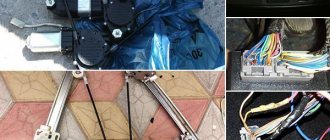
Rear door harnesses
The electrical wiring for the rear right and left doors is identical, using only two terminals. The rear door wiring harnesses are factory marked 2170-3724550-10.
| 1 | Block for connection to the rear wiring harness |
| 2 | Rear door lock motor |
Ideas for tuning and modifying the shield
VAZ 2110 dashboard: general information on icons How to tune the dashboard:
- Instead of a standard shield, install a more advanced one, with a navigator. In such devices, the arrangement of indicators and sensors will be different - the sensors are located on the right and left, and in the middle there is a navigator display. This tuning option is considered one of the most expensive.
- Install ready-made or develop your own scales for sensors. To implement this idea, you will need to completely remove the tidy and disassemble it, as well as disconnect the arrows from the sensors. The scales are installed on existing sensors and are securely fixed.
- Use of LEDs in lighting. The device will also have to be disassembled, but here the method is simpler. You don’t have to remove the arrows, you just need to turn off the light bulbs on the device and dismantle them, and then replace them with new ones. If the base of the light sources does not match, the lamps will have to be soldered. Alternatively, instead of light bulbs, you can solder an LED strip.
- Paint the dials and gauges of the instrument panel with fluorescent paint, but for greater effect, again, you will need to install diode lamps. With this combination, the tidy will glow brightly, but keep in mind that the implementation of this method requires care and painstakingness from the car owner.
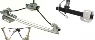
Types of PTF
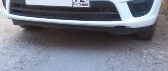
As you know, Priora underwent several stages of restyling, where one of the main changes was the bumpers. With the change in bumpers, the design of the PTFs themselves also changed.
In the old bumper, the fog lights had a round appearance, but in the new one they already received a frame in the shape of a triangle, but still with the same round headlight.
At first glance, you might think that they are exactly the same, but this is a wrong assumption; they have different mounting brackets. Therefore, it is important to know which bumper the PTF will be installed on.
There are two manufacturers of fog lights for Priora - BOSH and Kirzhach. It is difficult to notice any particular difference in the luminous flux of these manufacturers, but there are differences in the mounting for installation in them. It will be difficult to replace “BOSH” with “Kirzhach”; for this you will have to change the PTF spacer in the SE bumper.
There are two options for installing a pre-restyle Priora and a post-restyle Priora into the bumper (SE bumper, Priora 2).
Articles and price of PTF for PRIORA 1 (pre-restayl until 2012):
PTF Priora 1
PTF "Kirzhach": 21700-3743010-52. The price starts from 700 and reaches 1000 rubles. For one headlight, sellers ask from 500 rubles.
PTF "BOSCH": 21700-3743010-54. The price starts from 1500 and reaches 2000 rubles. For one headlight you will have to pay from 1000 rubles.
Articles and price of PTF for PRIORA 2 (restyled after September 2012):
PTF Priora 2 (with frame)
PTF "Kirzhach": 21700-3743010-53. The price starts from 800 and reaches 1100 rubles. For one headlight, sellers ask from 600 rubles.
PTF "BOSCH": 21700-3743010-50. The price starts from 1000 and reaches 1500 rubles. For one headlight you will have to pay from 700 rubles.
It should also be noted that not all stores come with a mounting kit of wires and relays for the PTF. It is necessary to check with the sellers whether they have an installation kit. Otherwise, you need to purchase it in addition. Its cost is from 600 rubles.
Analogs
If for some reason the models from and “Kirzhach” do not suit you, then you should not be upset. Currently, the market is simply filled with a huge number of Chinese-made analogues.
Manufacturers from China have a large selection of high-quality PTFs that are not inferior to more expensive models.
One of the most popular Chinese PTF models are headlights that completely cover the cutout for the fog lamp, that is, they have the shape of a triangle.
Connecting the interior lamp of the Priora
I would like to share with you my experience of installing rear passenger lighting. Installed due to lack of light from the driver's lamp. I often had to use a flashlight to find a bag or packages left in the back seat. I’ll make a reservation that the lampshade from the Priora Luxury is not too bright, so I’ll be finalizing it later and will definitely share my experience. But for now about the installation itself.
You need to purchase: - a lamp frame (130 rubles as of January 2017) - a lamp for illuminating the rear passengers (400-450 rubles) - 3 meters of wire (a thick wire is unnecessary here, since the power consumption of both lamps does not exceed 1A) - 3 pin connector (I didn’t find a native one for sale, so I used a computer 4 Pin (I’ll specify which one later) - 3 pin connector for connecting to the lampshade
And since I replaced the “standard” front lamp with a “luxury” one, I need two 3-pin blocks. I bought one in flames for 100 rubles (wow! for what?!). Then I looked in the bins and found a suitable 3 pin connector from the computer. This header connects to the motherboard and powers the Power LED on the case.
First, I cut off the connection block for the original lamp, because... I didn't find the answer to it.
Installation
- buy PTF (articles: 21900-3743011-00 and 21900-3743010-00), for example here. For Lada Granta FL, PTF catalog number: 261500097R.
- PTF activation button (article 759.3710-07.01A or 995.3710-07.06).
To install the PTF in the bumper, it must be removed. Then cut holes of the required diameter. Sand the sawn edges with sandpaper. And secure it to the fog lights in the bumper using screws. There shouldn't be any difficulties at this stage.
The whole process is also shown in the video:
Replacement and repair of the electrical package control unit 2170-3763040 Lada Priora
Modern versions of cars are supplied to the market with a restyled version of the tidy. Here, a relatively old generation, navigation and a liquid crystal display appeared. Installing an updated shield requires the following steps.
There are only two types of updated designs with and without a CAN bus. The nuance is that the versions are completely identical in appearance. In order to find out which variety is suitable, you need to check the production date of the car. Cars manufactured before 06, 2012 are not equipped with such technology. The article numbers of the new devices with navigation are as follows:
- 2170-3801010-50 without CAN;
- 2170-3801010-60 with CAN.
Read more: Electric power steering for the VAZ 2107: basic recommendations Also included in the kit is the need to purchase a navigation antenna and a steering column switch of the appropriate design.
Installation nuances
For Lada Kalina versions, all devices are not equipped with a CAN module. Also the old generation of Priora. Here the installation is carried out without modifications or nuances - just snap out the old panel, remove the terminals, and mount the new set on the stock fasteners. Next, you need to install a navigation antenna on the roof and connect it to the appropriate connector.
The second case is when an old panel with a CAN unit, but without navigation, is replaced with an analogue one. Here it is necessary to rearrange the contact connectors of the standard wiring from positions 10-11 to sockets No. 28-29. In case of incorrect operation of the devices, the replaced wires are swapped with each other. After the repair is completed, the counters should be reset to zero.
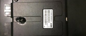
The electrical package controller is a device designed for installation on VAZ 2170 Priora cars. It controls many car functions, for example, turn signals, power windows, instrument panel lights, side lights, low beam, fog lights, reverse lamp, interior lighting, heated rear window.
This controller is installed in the central, lower part of the dashboard above the ECU unit. To remove it, you need to remove the lower sides of the torpedo. Using a socket wrench 10, unscrew the two nuts.
Priora electrical package control unit board 2170-3763040
Location of terminals of the Priora electrical package control unit 2170-3763040
Diagram of the Priora electrical package control unit 2170-3763040
POS - interior lighting lamp ZPTO - rear fog lights BS - low beam PTF - fog lights MDV - driver's door module PUP - turn signal switch PAS - hazard warning switch PPD - front right door PLD - front left door ZPD - rear right door ZLD - rear left door PS - passenger door power window switch FOB - trunk light ZP - right mirror ZL - left mirror GO - side lights UP - direction indicators
Messages 7
1 Topic by Admin 2013-07-05 13:09:37
- Admin
- Administrator
- Inactive
- Registration: 2012-02-20
- Messages: 3,257 Thanks : 624
Topic: Is it possible to connect the light control module from Priora to a VAZ 2110?
Ideally, I would like to get a working connection diagram for this module instead of the standard “decimal” ones that are on the instrument mask.
2 Reply from Serg 2013-11-02 14:17:26
- Serg
- Lada2111.rf fan
- Inactive
- Registration: 2013-07-29
- Messages: 830 Thanks : 363
- Car: 2111 dwg 2114 year 2008
Re: Is it possible to connect a light control module from Priora to a VAZ 2110?
Connecting a light control module from Priora
We have a module with one 12-pin connector (No., color in prior) wire purpose (function) 1 - orange-black - input indicating that the rear foglights are on 2 - orange-white - output controlling the activation of the rear + front foglights 3 - yellow - input indicating that the front ones are on prottumanok 4 - brown - output control the brightness of the backlight of the buttons 31 - black - ground (it is also mass in Africa) 30 - pink - input +12volts from the battery 56 - green - output +12volts turn on the head light 58 - whitechern - output +12volts turn on dimensions 56v - serkras - +12 volt input after turning on the head light to control the fog light 58v - white - input for the illumination of the Xz - synchern - +12 volts after the ignition switch G - blue - to control the headlight range control
56 Xz 31 58b 56b G 30 58 4 3 2 1
After comparison with the 2110-2112 scheme, the following came out:
1) it is possible to connect this unit without an electrical package control unit Priors without foglight controls (I will finalize it later) all other wires somehow match in color (.) must be connected to the connector (standard 2110) light control except for the following wires: 1 – orange-black, 2 – orange white, 3 – yellow, 4 – brown (use standard regulator 2110), G – blue (if you want to connect the headlight range control, knock on the priors)
2) it is possible to install a control unit for the Priora electrical package (but later)
3 Reply from Admin 2013-11-13 13:45:45
- Admin
- Administrator
- Inactive
- Registration: 2012-02-20
- Messages: 3,257 Thanks : 624
Re: Is it possible to connect a light control module from Priora to a VAZ 2110?
That is, here are the contacts of the ICC Priora that should be used? 31- black - ground (it is also mass in Africa) 30- pink - input +12 volts from the battery 56- green - output +12 volts turns on the head light 58- belchern - output +12 volts turns on the headlights 56v-serkras - input +12 volts after turning on the headlight light for control fog 58V - white - input to the Xz block illumination - synchern - +12 volts after the ignition switch
Here is the standard switch for the low beam and dimensions of the old-style instrument panel (on diagram No. 36)
30 (pink) - connect to 56 (green) 58 (white-black) - connect to 31 (black) 56 (green) - connect to 58 (belchern) X (blue-red) - this is also a mass.
I found the remaining contacts in the VAZ 2110 mounting block: Ш3-4 (+12V) - connect to 30 (pink) Ш3-1 or Ш3-3 - connect to 56V (serkras) Ш2-8 - connect to 58V (white) Ш1-4 and Ш4-17 - connect to Xz (synchern) Is that right?
I looked at the contacts from the mounting block here
4 Reply from Serg 2013-11-13 16:20:04 (2013-11-13 16:50:09 edited by Serg)
- Serg
- Lada2111.rf fan
- Inactive
- Registration: 2013-07-29
- Messages: 830 Thanks : 363
- Car: 2111 dwg 2114 year 2008
Re: Is it possible to connect a light control module from Priora to a VAZ 2110?
No, it’s not right on the standard light switch 2110 to connect all the wires in the same colors with the Priora IUS, something like this
Priora 2110-212 30 (pink) - connect to 30 (pink) 58 (white-black) - connect to 58 (belcher) 56 (green) - connect to 56 (green) X (blue-red) - X (blue-black) +12 volts after the ignition switch
The wires of the MUS Priors 1 - orange-black, 2 - orange-white, 3 - yellow, have a trigger switch (i.e. pressed once, turn on a second time, turn off) the triggers are located in the Priora's electrical package unit, so simply connecting them to 2110 will not work, you need to come up with a diagram
Additional brake light
The additional brake light uses LEDs instead of lamps. If the LEDs are faulty, the lamp assembly must be replaced. The work is shown on a hatchback car. On a sedan car, the light is secured to the rear window shelf from below with two screws from the luggage compartment.
Installing an additional brake light may require two new headliner brackets.
1. We prepare the car for work.
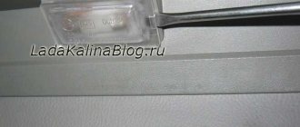
2. Having opened the tailgate, use a slotted screwdriver with a thin blade to remove two plugs from the housing of the additional brake light.
In addition to the flashlight wires, a rear window washer tube is routed through the corrugated hose. As a result, it is difficult to pull out the wires, much less re-stretch them together with the block.
6. Mark the colors of the wires on the block and use an awl or a screwdriver with a thin blade to release the wire retainer.
7. Remove the wire clamp from the block.
8. Use a needle or the end of a metal clip to tighten the tip lock and remove the wire tip from the block.
9. Similarly, remove the tip of the second wire from the block.
10. Remove the rubber seal from the door opening.
11. Pull the flashlight wires out of the corrugated hose.
12. Pull the wires out of the door hole.
13. Using an 8 mm socket wrench, unscrew the two nuts securing the additional brake light.
14. Remove the additional brake signal light from the car.
Install the additional brake signal light in the reverse order.
Warning!
We connect the wires to the block taking into account their color. You can check the correctness of the connection by focusing on the block of wires under the upholstery: the wires should be connected to the connector so that the red wire is located opposite the red one, and the black wire is opposite the black one.
Pinout for left front door
Most modern vehicles are equipped with a variety of driver comfort systems, one of which is the driver's door module.
The function of the button block located on the driver's door is to control the front windows and exterior mirrors, as well as the automatic locking of the car doors. The installed auxiliary left rear wiring harness (part number 21703-724551-90) comes complete with contact carriers made of electrically conductive materials.
| Contact no. | Decoding |
| 1 | Connector for the additional rear left harness to the rear harness |
| 2 | Rear left harness connector to front left speaker |
| 3 | Electric window lift |
| 4 | Armrest control module |
| 5 | Electric drive for locking the left front door |
| 6 | Left outer rear view mirror control chip |
Location of Priora fuses under the hood
- F1 (30 A) – power supply fuse for the electronic engine control system (ECM);
- F2 (60 A) – fuse for the power supply circuit of the engine cooling system fan (power circuit), additional relay (ignition relay), rear window heating, electrical package controller;
- F3 (60 A) – fuse for the power supply circuit of the electric fan of the engine cooling system (relay control circuit), sound signal, alarm signal, ignition switch, instrument cluster, interior lighting, brake light, cigarette lighter;
- F4, F6 (60 A) – generator power circuit fuses;
- F5 (50 A) – fuse for the power supply circuit of the electromechanical power steering
Relay and fuse box for Halla air conditioner
- right electric fan power supply fuse (30 A);
- fuse for the power supply circuit of the left electric fan (30 A).
- right electric fan relay;
- additional relay (sequential activation of left and right electric fans);
- left electric fan relay;
- heater fan power supply fuse (40 A);
- compressor power supply fuse (15 A);
- heater fan relay;
- compressor relay.
Panasonic air conditioner relay and fuse box
- Heater fan maximum speed
- Right fan
- Fan sequential relay (low speed)
- Left fan
- Left fan fuse (low speed)
- Right fan
- Heater fan
- Compressor
- Heater fan
- Compressor
Front Passenger Door Wiring Harness
The electrical wiring of the left and right front doors of the car differs in the additional control buttons for mirrors and power windows on the driver's door.
The factory original front passenger door wiring harness, part number 21703-3724550 -90, duplicates the power supply from the passenger door center front keypad.
There are 7 connectors coming out of the harness.
| Contact no. | Decoding |
| 1 | Connector of the right rear additional harness to the rear harness |
| 2 | Rear left harness connector to front speaker |
| 3 | Window lift motor |
| 4 | Electric window lift switch |
| 5 | electric front passenger door lock |
| 6 | Motor controls the position of the outer right mirror and its heating |
| 7 | Connector of the right rear additional harness to the rear harness |
Repair of the ICC
To repair the light control unit, you only need a little skill in using a soldering iron, the soldering iron itself and solder.
To repair the light unit, it must be dismantled.
Remove the fuse box cover by turning the three fasteners 90°.
We unscrew the screw securing the MUS, take it out and disconnect it from the chip.
Disassembling the module
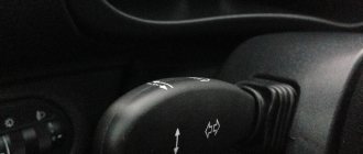
Pull the switch up and remove it, then use a screwdriver to pry up the bottom of the switch and remove it.
Carefully bend the 4 plastic clips, be careful the plastic is not elastic and breaks easily.
We remove the front cover of the MUS and take out the board by pressing on the contacts from the back side, the board will rise. Do not use too much force to avoid damaging the board!
The light control unit is disassembled and you can start soldering. The photo shows the places that are most subject to load and are the culprits in the malfunction of the module; they need to be soldered.
After the contacts are soldered, it is recommended to clean the contact stain with a file or sandpaper.
After the repair, we assemble the module in the reverse order and install it in place.
As you can see, there is nothing complicated in repairing the light control unit.
Source
Delivery by transport company (cash on delivery, no prepayment)
Advantages:
- the cost of delivery of heavy and large-sized orders is much cheaper than that of Russian Post;
- There are practically no restrictions on the weight and dimensions of cargo;
- There is a wooden crate service - this is an additional guarantee of the integrity of the order.
Disadvantages: unfortunately, there are branches only in cities.
The estimated cost of delivery for an order up to 30 kg is 450 rubles.
List of transport companies with which we cooperate:
- TC "PEK" (cash on delivery service available);
- TC "Business Lines";
- TC "Energia";
- TC "KASHALOT" (KIT) (cash on delivery service available);
- TC "SDEK" (cash on delivery service available);
- TC "DPD";
- TC "ZhelDorExpedition";
- TC "VOZOVOZ";
- TC "Baikal-Service".
To send your order by transport company:
The cost of delivery is calculated based on the volume, weight of the selected product and the distance from the city of Tolyatti.
To send an order you must:
- indicate full name recipient;
- Your locality and region;
- series, number of passport or driver's license;
- Your phone number (contact).
TC "Business Lines" - Urgent delivery of goods from 1 kg throughout Russia. The exact cost can be found on the official website of the delivery service - https://www.dellin.ru
Delivery time and cost Track the parcel View the list of branches
TC "PEK" - Guaranteed safety of cargo for the entire duration of cargo transportation, clear information support, delivery of goods throughout almost the entire territory of Russia, Belarus and Kazakhstan in optimal terms and accurately calculated cost of services. The exact cost can be found on the official website of the delivery service https://pecom.ru/ru/calc
Delivery time and cost Track the parcel View the list of branches
TC "SDEK" - Low tariffs compared to foreign courier companies, while the quality of the services provided meets modern international logistics requirements. Developed network of own representative offices. The exact cost can be found on the official website of the delivery service https://www.cdek.ru/calculator.html
Delivery time and cost Track the parcel View the list of branches
TC "ZhelDorExpedition" - Serves only large cities and towns. The exact cost can be found on the official website of the delivery service - https://www.jde.ru/branch
Delivery time and cost Track the parcel View the list of branches
TC "Energia" - Cargo transportation in Russia, CIS and China. The exact cost can be found on the official website of the delivery service https://nrg-tk.ru
Delivery time and cost Track the parcel View the list of branches
TC "KASHALOT" (KIT) - Delivery of cargo from 1 kg to 20 tons throughout Russia and Kazakhstan. The exact cost can be found on the official website of the delivery service https://tk-kit.ru/calculate
Delivery time and cost Track the parcel View the list of branches
TC "Baikal-Service" - Transportation and delivery of consolidated cargo by road across Russia. The exact cost can be found on the official website of the delivery service https://www.baikalsr.ru
Delivery time and cost Track the parcel View the list of branches
TC "DPD" - Transportation and delivery of groupage cargo by road in Russia. The exact cost can be found on the official website of the delivery service https://www.dpd.ru
Delivery time and cost Track the parcel View the list of branches
TC "VOZOVOZ" - Transportation of groupage cargo by regular delivery routes between Russian cities. The exact cost can be found on the official website of the delivery service https://vozovoz.ru
Delivery time and cost Track the parcel View the list of branches
Instructions for replacing the tidy yourself
The procedure for removing, disassembling and replacing the control panel can be carried out on your own; there is nothing complicated about it.
How to remove the PP:
- First of all, turn off the ignition, and then disconnect the battery from the power supply.
- For greater convenience, you should remove the steering column cover, and also dismantle the steering wheel itself.
- After this, using a screwdriver, you need to unscrew the two screws that secure the upper part of the tidy.
- Next, two more screws are unscrewed, only now from the bottom.
- There are two more screws on the sides of the control panel; they also need to be unscrewed.
- After this, you can pull the tidy towards you, but do not remove it completely. Since wires are connected to the device, you need to disconnect the connectors on the back side, and then release the latch.
- The PP is removed and replaced with a new one. Assembly steps are carried out in reverse order.
How to determine the malfunction?
If you notice that there are problems with the wiring of the Priora or one of the devices is not functioning, then you can diagnose the voltage using a multimeter. In particular, you will need to check whether there is voltage in the power circuit connecting the failed device to other devices.
How to do it correctly:
- First you need to switch the tester to voltmeter mode.
- Next, one tester probe is connected to the battery or vehicle body, depending on where the device being diagnosed is located.
- The second probe of the device must be connected to the supply cable in the circuit being diagnosed, but before this the terminals from the device must be removed.
- If, during diagnostics, readings appear on the tester screen, this indicates that there is voltage in the circuit, and accordingly, the tested wires are in good condition.
- Similar actions are performed with the remaining wires that require checking. If you eventually find a point where there is no voltage, then this indicates that the source of the breakdown is located in this section of the circuit. The only thing left to do is just find the cause and get rid of it (the author of the video is the PRO.Garage channel).
If there is no voltage in the circuit at all, you can diagnose a possible short circuit.
To do this, follow these steps:
- First, you need to remove the part that is responsible for the circuit being diagnosed from the fuse block.
- As in the previous case, the multimeter should be activated in voltmeter mode.
- One tester probe should be connected to the safety element connection outputs. Make sure that all other equipment and devices in this circuit are not connected.
- Then move the wire itself a little - if at this moment indicators appear on the display, this indicates that the wire is shorting somewhere. The problem must be solved as quickly as possible - qualified electricians say that in principle it is not worth bringing the electrical circuit to such a state.
A short circuit usually appears in that section of the circuit where the insulation has worn off. This procedure can be carried out with any component of the electrical circuit, as well as with switches. If the diagnostics showed the absence of a short circuit, then there is another test option.
In particular, we are talking about searching for a possible break in the electrical network, the procedure is performed as follows:
- First you need to turn off the power to the on-board network or just one area that you want to check. To do this, either disconnect the terminals from the battery, or simply remove the safety device from its mounting location.
- Now we proceed directly to the test - the tester probes should be connected to the two ends of the electrical circuit section.
- Next, one of the probes should be connected to the car body; you need mass.
- If, at the time of connection, indicators begin to appear on the tester’s display, this indicates that there are no breaks in this section of the electrical circuit. If there are no changes, then we can say with confidence that there is a break in the wiring.
Fuse box in the passenger compartment of VAZ-2170, -2171, -2172
The fuse box in Priora is located at the bottom of the dashboard, on the left side of the steering wheel. To get to it, you need to open the cover, which is held on by three latches. Rotate each locking knob 90 degrees and pull the lid down and it will snap open.
Fuses in the interior mounting block
F1 (25 A) - radiator cooling fan. If your fan does not work, check its motor by applying 12 V directly to it from the battery. If the engine is working properly, then most likely the problem is in the wiring or connectors. Check the serviceability of relay K1.
The fan in the Priora usually turns on at a temperature of 105-110 degrees. Do not allow the engine to overheat, watch the arrow of the temperature sensor.
If the fan runs constantly and does not turn off, check the coolant temperature sensor located on the thermostat. If you remove the connector from the working sensor, the fan should turn on. Check the wiring to this temperature sensor, as well as the contacts of relay K1, move this relay, clean the contacts. If this is the case, replace it with a new relay.
F3 (10 A) - high beam, right headlight. F4 (10 A) - high beam, left headlight. If the headlights do not shine on high beam, check the K7 relay and the headlight bulbs. The steering column switch, wiring or connectors may also be faulty.
F5 (10 A) - sound signal.
If the signal does not work when you press the steering wheel button, check relay K8. The signal itself is located under the radiator grille; you can get to it by removing the plastic casing from above. Check it by connecting the voltage to 12 V. If it doesn’t work, try turning the adjusting screw, or replace it with a new one.
F6 (7.5 A) - low beam, left headlight. F7 (7.5 A) - low beam, right headlight. When replacing lamps, be careful; there are separate lamps for the low and high beams, so they can be easily confused. It is better not to install lamps in high-power headlights; the reflectors may melt and the desired effect will not be achieved. Most low beam headlight problems that cannot be corrected by conventional means can be related to the light control module (LCM). The low beam relay is only available in cars equipped with a light sensor, it is located in the place of relay K1; on most cars this relay is not in the mounting block; the low beam circuit goes through the MUS block. It happens that the tracks in the block burn out; if there are problems, it is better to replace it with a new one. If the windshield wipers turn on spontaneously when the low beam is not working correctly, the problem is most likely in the windshield wiper control unit, located in the center of the dashboard, the topmost block, next to the radio, is best reached from the glove compartment, or by hand through the removed console covers at the feet.
F8 (10 A) - alarm signal. If the alarm does not work, also check relay K9.
F9 (25 A) - stove fan.
If your stove does not work in any mode, the problem may be with the stove speed controller or with the engine. Check the stove motor by applying 12 V voltage directly to it. If it does not work, remove it, open the cover and check the condition of the brushes. If the stove does not work only in the first modes, but works in the last mode, most likely you need to replace the heater resistance, located under the hood on the fan scroll.
The price of these resistors is about 200 rubles. Also check that the filter and all pipes are clean and that air flows normally into the stove. If the stove fan squeaks or turns with difficulty, try lubricating it. If the stove turns on and off, check the connectors and contacts in them, they could have melted or oxidized, in this case, replace the connector.
Possible wiring faults
What malfunctions in the operation of the on-board network may a car owner encounter:
- The device itself does not work. For example, the rear window heating system or the electric side mirror controller refuses to function. There is a possibility that the reason lies in the device itself or the fuse that is responsible for its operation.
- Short circuit in the electrical network. As stated above, a short circuit problem usually manifests itself as a result of insulation failure in one area or another. To prevent this, wires should be laid in places where there are no moving elements.
- Broken wiring. This malfunction is typical for many Russian-made cars. To prevent a breakdown, consider the recommendations described in the paragraph above.
- Failure of the safety element. If you notice that malfunctions have begun to appear in the operation of certain devices, then first you should open the mounting block and check the integrity of the fuse itself. There is a possibility that this is where the problem lies. Typically, safety devices break due to too high voltage in the on-board network. If the reason really lies in overvoltage, then first you need to eliminate the problem itself, and only then change the fuses.
- Lack of contact. In this case, a section of the circuit may be intact, but there will be no contact. Most likely, in this case, the problem lies in the fact that the wire has come off a little or the contact at its end has oxidized. In this case, the contact is cleaned using a brush or sandpaper, after which the wire is reconnected.
Photo gallery "Wiring faults"
Opel Astra TURBO RESTYLING › Logbook › Replacement of interior lighting lamps!
Hello to all readers of my logbook!))) It’s immediately clear that the yellow light in the car is nothing... I decided to replace the standard lamps with LEDs! They were replaced a long time ago, but I just couldn’t get it together, choose the time and create a BZ...))) I bought 5 baseless LEDs for the lampshades, 4 LEDs for illuminating the sun visors
Then I took the lights apart. Disassembling the lights is simple, all fastenings are snapped, carefully pry and remove...
I didn’t install a central LED, because I don’t need light when opening the door, and in the future the lights for the legs and doors will be connected to this connector, but more on that in the next blog…)))
Then we put everything together and here is the result:
The central section does not light up, only the outer sections light up. There is plenty of light...
Then we move on to the rear courtesy lamp. Everything is sorted out and changed in exactly the same way...
Then we move on to illuminating the glove compartment. The yellow light in it doesn’t inspire me either... So I took out the flashlight, pulled out the old lamp and inserted a new diode... To pull out the flashlight you need to pry it off with a flat screwdriver, as if from the inside...
The only thing left to do is to replace the lamps in the sun visors... As with all lampshades, it is extremely simple... The glass is removed, the lamp is taken out and the diode is installed... But there were some problems, the diodes were larger than the original lamps, so they had to be filed a little))) Unfortunately there are no photos of the finalization...
I immediately thought that the diodes would produce less light, but it turned out to be the opposite... Overall, I’m very pleased with the result, white light is much nicer!))) Don’t forget to comment and like!))) If you like it, of course!))) Thank you all for your attention! )))
Price: 500 ₽ Mileage: 1000 km
CBKE errors
- * there is no fault code in TsBKE 21900-3840080-10;
- If an “active” fault code is detected, perform the checks outlined in the “diagnostics” column;
- After troubleshooting, clear fault codes using a diagnostic tool.
Deciphering fault codes
:
- B1002 Open in driver lock control circuit
- B1004 Open in the front left window control circuit
- B1006 * Open in the rear left window control circuit
- B1008 Open in the alarm sound control circuit
- B1010 Open in the trunk gear motor control circuit
- B1012 Open in the passenger lock control circuit
- B1014 Open in the front right power window control circuit
- B1016 * Open in the rear right window control circuit
- B1017 ROM checksum error of the central unit of body electronics
- B1018 Short circuit in the rear window heating relay coil circuit
- B1019 Short circuit in the windshield heating relay coil circuit
- B1020 Short circuit in the seat heater relay coil circuit
- B1021 Wiper malfunction
- B1023 Short to ground or overheating in the control circuit of the common board bus
- B1027 Malfunction of the power window control keys in the passenger doors
- B1028 * Short to ground in the rain sensor sensitivity regulator circuit
- B1030 Open circuit (lamp burnout) of daytime running lights
- B1031 * Open circuit in the rain sensor sensitivity regulator circuit
- B1033 Open (lamp burnout) in the left turn signal circuit
- B1034 Open (lamp burnout) in the right turn signal circuit
- B1040 Open or short to ground in the low beam headlight relay coil circuit
- B1041 * Short circuit in the automatic lighting control relay coil circuit
- B1042 Short circuit in the high beam relay coil circuit
- B1043 Short circuit in the low beam relay coil circuit
- U1044 Lack of communication with MDV
- U1045 Communication error with MDV
- U1046 * Communication error with rain and light sensor
- U1047 * No communication with rain and light sensor
- U1048 CAN bus fault
- B1049 High voltage on-board network
- B1050 Low voltage on-board network
- B1051 * Short to ground in the right mirror control circuit
- B1052 * Left Mirror Control Circuit Malfunction
- B1057 Internal malfunction of the MDV
Also using this program you can configure the central unit of the body electronics.
Set the delay for turning on the wipers after the washer is activated (from 0 to 2.56 sec).
Activate or deactivate the function of turning on the interior lamp when the ignition is turned off
Set the delay for turning off the interior lamp when closing the door (from 0 to 60 sec)
Set the delay of the energy saving mode (power loss on the interior lamp, trunk, control wire of the radio (Kalina 2) (from 0 to 10 min)
Activate or deactivate the stepwise door unlocking mode, as well as the automatic door unlocking mode when the ignition is turned off
Activate or deactivate the automatic mode of raising/lowering the driver's window
More details about the TsBKE block are described in Technological Instructions (TI) 3100.25100.12051, which you can download here.
All reference information on models
:
- Lada Granta
- Lada Kalina
- Lada Priora
Keywords: Lada Priora windshield wipers | windshield wipers for Lada Granta | windshield wipers Lada Kalina | heating for Lada Granta | heating Lada Kalina | heating for Lada Priora | external lighting for Lada Granta | external lighting for Lada Priora | external lighting for Lada Kalina | interior lighting for Lada Granta | interior lighting for Lada Kalina | interior lighting for Lada Priora | window lift for Lada Kalina | window regulator for Lada Granta | Lada Priora window regulator
5
Found an error? Select it and press Ctrl+Enter..
Personalize existing features
The manufacturer has provided for the timing of regular technical inspections, which are mandatory. For non-compliance, the company reserves the opportunity to deprive the car owner of the right to free service.
The most vulnerable is the comfort block, which includes many logical circuits. Its purpose boils down to the following functions:
- activation of interior lighting;
- adjusting the operation of car alarms;
- turning on the heated rear window;
- automatic mirror adjustment;
- control of electric windows;
- remote control of locks.
The manufacturer has provided the ability to personalize each element. To do this, the electrical package control unit must be recoded at an authorized automotive center. Using official software, the wizard will add or remove certain features. If everything is done correctly, 20 minutes after requesting the appropriate service, you can safely use the “iron horse”.
According to reviews from car enthusiasts, the Lada Kalina car is distinguished by electronic filling with increased sensitivity to operating conditions. Aggressive driving style and minor damage lead to malfunctions.
As a result, you need to visit a service station to replace the device. To do this, remove the control unit, which must be done as follows:
- turn off the battery;
- unscrew the screws from the driver's seat;
- Use a ratchet wrench to remove the nut;
- the plastic plug is squeezed out completely;
- carefully pull out the seat;
- remove the seat by dismantling the terminals;
- remove the cover plate.
Lada Kalina Hatchback 2010, 80 l. With. — tuning
Lada Kalina, 2012
Comments 54
Hello, can you tell me if the front fog lights are on, what needs to be switched off so as not to burn anything? There is no MUS, I need to check!
I actually threw out this block, installed 2 4-pin relays and a switch for the turn signal from a foreign car and everything worked. and thank you so much for the pinout diagram)
The dimensions are supplied with a black and white cable (58) from pin #9, which in the MUS is connected from pin #11 - pink cable (30). For the low beam there is a green cable (56) from contact #12, which in the MUS is connected from contact #10 - a blue-black cable (Xz). IMHO: only contacts #10 with #12 can be shorted with jumpers without consequences. Contacts #10 and #9 are never bridged in the ICC, respectively, when they are bridged and the knob is turned to the “dimensions” or “low beam” position, contacts #10 and #11 (pink and blue-black cables) are bridged. Hence your phenomenon of the engine running without a key since 12 volts are sent to the ignition in the opposite direction through the blue-black cable. How unsafe this is for electrical and electronics is doubtful for me personally...
Safe, I tried it. When installing a jumper between contacts 10 and 9 and turning on the ICU in the “dimensions” position, contacts 9, 10 and 11 are connected, and in the “low beam” position 12 is added to them, that is, ALL four are connected (as if both jumpers). But it’s also a plus in Africa, it can’t go in the “that” or “reverse” direction, plus 12V plus 12V can’t be burned out, at least in this case. Yes, the ignition is kept on if you set the MUS to “dimensions” (it also turns on without a key, as if the key was inserted and turned to the ignition: the instrument lights up, the heater fan turns on, etc.). This also seemed convenient to me, the previous car had autostart, but this one does not have it YET, but thanks to MurZone, now we know an intermediate solution on how not to freeze next to the car while it is warming up. It’s a pity that when the ignition is on, the doors do not close with the key (although they OPEN), but if necessary, they can be closed manually mechanically. I decided to go a little further and not just threw a jumper, but soldered taps to all four wires (9,10, 11 and 12) and brought them out into two relay blocks - maybe someday I’ll implement more complex on-off algorithms (then You will also need a minus from pin 8). In the meantime, instead of a relay, I stuck a jumper between 10 and 9 and am very pleased. By the way, if for some reason you don’t want the ignition support effect when the lights are on, just put a diode in the jumper.