Table with errors
A complete list of faults with explanations and recommendations for troubleshooting:
| Error | Sensor malfunctions |
| P0030 | Code P0030 (0030) indicates a malfunction of the oxygen control controller. The problem was detected by the engine control unit as a result of driver diagnostics. To fix the problem, you need to check the electrical circuit of the heating element for a break. |
| P0032 | Code P0032 indicates a short circuit in the control circuit of the heating element of the lambda probe to the on-board network |
| P0036 | Combination P0036 (0036) appears as a result of a malfunction in the electrical circuit that supplies the heating element of the oxygen controller. This refers to a sensor installed after the neutralizer device. The error indicates an open circuit, so first of all you need to check its integrity. |
| P0102 | Code P0102 (0102) indicates a malfunction of the mass air flow controller. The cause of the malfunction is damage to the flow meter wiring. The error may be intermittent, so to fix it, you need to try cleaning or replacing the air filter. The cause of the problem may be damage to the wiring on the microprocessor module connector. To check the flow meter, perform the following steps:
|
| P0103 | The control unit has detected an incorrect signal coming from the mass air flow sensor. Electrical circuit diagnostics required. |
| P0112 | Code 0112 indicates problems with the incoming air temperature controller. It is necessary to check the operation of the sensor, as well as its wiring. |
| P0113 | Code P0113 (0113) appears as a result of incorrect operation of the incoming air temperature controller |
| P0116 | Combination 0116 is associated with an incorrect signal coming from the coolant temperature sensor. The reason may lie directly in the regulator or the integrity of the power line. |
| P0117 | Incorrect signal from antifreeze temperature regulator |
| P0118 | Error P0118 (0118) appears as a result of an increased signal recorded on the refrigerant temperature sensor line |
| P0122 | Code P0122 (0122) is a consequence of an incorrect pulse supplied from the throttle position sensor. There may be interference in the circuit if the line is damaged. |
| P0123 | The microprocessor module has detected that the throttle position controller is sending an incorrect signal. The pulse is out of range. A detailed check of the wiring is required, as the cause may be damage. |
| P0130 | Combination P0130 (0130) appears as a result of damage to the electrical circuit of the control oxygen controller. Possible short circuit of contacts. |
| P0131 | Code 0131 reports low voltage in the electrical circuit of the oxygen control controller |
| P0132 | Combination 0132 indicates an increased voltage signal coming from one of the control oxygen controllers |
| P0133 | Code 0133 literally translates as “diagnosis of a slow response from the control oxygen sensor.” The problems are related to the signal coming from the device. |
| P0134 | Combination P0134 (0134) appears as a result of a decrease in voltage in the electrical circuit of the control lambda probe |
| P0135 | Combination P0135 (0135) is associated with damage to the heater of one of the oxygen controllers. The reason may be a faulty electrical circuit. |
| P0140 | Code 0140 indicates a lack of activity in the power line of the oxygen controller installed after the converter |
| P0222 | Second throttle position sensor voltage too low |
| P0325 | Code P0325 (0325) is associated with an open circuit in the detonation controller |
| P0326 | Code P0326 (0326) appears as a result of the signal supplied from the knock regulator being outside the normal range |
| P0327 | Code P0327 (0327) indicates a reduced signal level coming from the knock controller. It is necessary to check the quality of the sensor's connection to the network. |
| P0328 | Combination P0328 (0328) reports an excess of the signal coming from the engine knock sensor. If the controller is faulty or there is a break in the electrical circuit, the problem may be accompanied by unstable operation of the engine and its random stopping. |
| P0336 | Code 0336 indicates a breakdown of the crankshaft position sensor or damage to its wiring. |
| P0337 | Code 0337 appears as a result of a short to ground in the crankshaft position controller. It is necessary to check the contacts and wiring of the sensor. |
| P0340 | Code P0340 (0340) indicates problems with the camshaft position sensor. The signal coming from the controller does not change in a car with the engine running. If the dashboard shows this error, the user needs to diagnose the sensor electrical circuit. Since the regulator is installed in the engine compartment, the contact on its wiring connector could be clogged. |
| P0341 | Error P0341 (0341) appears as a result of failure or malfunction of the camshaft position sensor |
| P0342 | Code 0342 is associated with a faulty phase sensor. If the controller is faulty, the power unit may detonate during operation. The damaged wire is replaced, and the contacts on the regulator power connector are also cleaned. A failed sensor must also be replaced. |
| P0343 | Code number P0343 (0343) on an 8- or 16-valve Priora with BC (on-board computer) State indicates a fault in the electrical circuit of the phase sensor. The signal coming from the controller is too high. A complete check of the device and its wiring is necessary; perhaps the cause is a short circuit. You may need a multimeter to troubleshoot. |
| P0346 | Malfunction of the phase sensor |
| P0500 | Combination P0500 (0500) appears when the speed controller is not operating correctly. The vehicle speed may be below the threshold. A detailed diagnosis of the signal coming from the regulator is required. |
| P0501 | Error P0501 (0501) indicates an incorrect signal coming from the speed sensor. If the device itself is working and its electrical circuit is intact, then to find the cause, detailed diagnostics of the microprocessor module will be required. |
| P0504 | Code P0504 (0504) appears as a result of a malfunction of the brake pedal controller. The on-board computer diagnoses the mismatch of pulses coming from the devices. Controller signals change inconsistently, which may indicate a malfunction or problems with wiring integrity. Most likely, the cause of the problem is contamination of the contact of the sensor installed on the pedal. |
| P0505 | Code 0505 indicates a malfunction of the idle speed controller. Failure of the regulator can cause a sharp jump in speed. |
| P0511 | Combination P0511 (0511) appears as a result of a malfunction in the idle speed sensor power line. It is necessary to completely check the wiring, test it and diagnose the contacts on the connector. The reason may be that the insulation on the main power cable is worn out. |
| P0830 | Error 0830 indicates a faulty clutch switch. It is necessary to check the operation of the sensor installed directly on the pedal; a wire break or damage to the connector is possible. The problem may be accompanied by increased fuel consumption and failures when shifting gears. |
| P1135 | Code P1135 (1135) The microprocessor module has detected a break or short circuit in the line of the heating element of oxygen sensor 1. The wiring integrity must be checked. |
| P1141 | The error is due to the inoperability of the heating element of the first lambda probe installed after the converter |
| P1513 | Combinations P1513 (1513) appear as a result of a short circuit on the idle speed controller line. Diagnostics of the contacts on the sensor connector is required. |
| P1514 | Code P1514 (1514) appears as a result of an open or short circuit in the wiring of the idle speed sensor. It is necessary to check the integrity of the pins on the block and ring the electrical circuit. A faulty controller must be replaced. |
| P1617 | Code 1617 indicates an increased signal level in the electrical circuit of the rough road controller. In general, this error will not affect the operation of the engine in any way. |
| R2020 | Combination 2022 is associated with a malfunction of the intake shaft flap position controller |
| P2122 | Code P2122 is associated with a reduced signal from the gas pedal position sensor |
| P2127 | The voltage in the electrical circuit of the gas pedal position controller is below the permissible value |
| P2138 | Error P 2138 appears as a result of checking the mismatch of pulses received from two gas pedal controllers. The voltage level in the sensor electrical circuit does not correspond to the standardized value. |
| Code | Engine malfunctions |
| P0101 | Error P0101 (0101) indicates that the air flow readings from the sensor are incorrect. Detailed diagnostics of the controller is required; it may need to be cleaned. |
| P0121 | Open circuit of the third injector. With this problem, the engine may not operate correctly. |
| P0171 | Code P0171 (0171) indicates a malfunction in the fuel supply system. The error appears as a result of a lean combustible mixture. |
| P0172 | Codes P0172 (0172) indicate that the air-fuel mixture is rich. It is necessary to check not only the engine cylinders, but also the elements that influence its formation. This refers to the air filter and flow meter. The cause of the problem may be a lack of tightness. |
| P0204 | If on a VAZ Euro it was possible to read VDO code 0204, this indicates a break in the wiring in the electrical control circuit of the fourth cylinder injector. |
| P0300 | If error P0300 (0300) occurs, the control unit reports that the threshold value for misfire of the air-fuel mixture has been exceeded. It is necessary to accurately check their number. |
| P0301 | Code P0301 (0301) appears as a result of misfire in the first cylinder of the engine |
| P0302 | Misfire in the second cylinder of the power unit. It is necessary to check the operation of the mass air and oxygen flow sensors. |
| P0303 | Code P0303 (0303) indicates detection of misfire in the third cylinder of the engine |
| P0304 | The appearance of error P0304 is also associated with misfires for toxicity. Their number is significantly higher than the nominal threshold. |
| P0335 | Code P0335 (0335) indicates a crankshaft (crankshaft) synchronization error. The first thing to do is check the operation of the crankshaft controller and its wiring. |
| P0363 | Code P0363 (0363) indicates a misfire in one of the engine cylinders. The ECU (electronic control unit) has cut off the fuel supply to the idle cylinders. Possible causes of the problem:
If replacing the fuel does not help, it is necessary to diagnose the air intake system. You should tighten the fastening clamps, change the air filter element and check the pressure in the rail (the normalized value is no more than 2.8 atm). It is also necessary to perform diagnostics:
Diagnostics of high-voltage wires is carried out using a tester; it is necessary to check the resistance. If the obtained value is more than 10 kOhm, then the cables must be replaced. You also need to check the integrity of the spark plugs and make sure there is no carbon deposits on their tips. If the described actions do not help determine the cause, the cylinders are diagnosed. The user needs to check the compression level, which should be approximately the same in each device. If the obtained values differ by more than 0.5 atm, then the power unit needs to be tested in more detail. |
| P0422 | Combination P0422 (0422) indicates a malfunction of the neutralizer device. Literally, the code can be deciphered as “determining the oxygen capacity by comparing the amplitude range of two lambda probes - diagnostic and oxygen.” In other words, the aging coefficient of the neutralizing device is greater than the upper maximum value. It is necessary to check the operation of the sensors and replace them if necessary. The cause of the problem may be poor contact between the controllers and the network. |
| P0441 | Combination P0441 (0441) literally stands for “incorrect response of the idle speed support system, the value is higher or lower than the threshold.” The malfunction indicates problems in the operation of the canister purge valve. It is necessary to diagnose the device and clean it; if this does not help, the mechanism should be replaced. |
| P0443 | Code P0443 (0443) reports a malfunction in the electrical circuit for controlling the adsorber purge valve |
| P0444 | Driver diagnostics showed a break in the electrical line of the canister purge valve |
| P0485 | Malfunction of the engine cooling fan - the voltage level on the line is less than or greater than the threshold value. It is necessary to diagnose the signal coming from the device. The cause of the problem may be oxidation or clogged contacts on the fan power connector. |
| P0506 | Reduced idle speed of the power unit |
| P0507 | Combination P0507 (0507) indicates increased speed of the power unit in the idle system. The cause of the problem may be the sensor or its wiring. |
| P1140 | Combination 1140 literally stands for “measured engine load differs from calculation.” There can be many reasons for this problem, ranging from incorrect compression to malfunctions in the microprocessor module. |
| P1301 | The appearance of error P1301 (1301) is associated with the excess number of misfires to protect the converter. A decrease in quantity may negatively affect the functioning of the latter. |
| P1302 | Code 1302 A large number of misfires in the ignition system to protect the neutralizer device |
| P1303 | A misfire was detected in the third cylinder of the engine, which may affect the operation of the converter. |
| P1304 | Code 1304 appears as a result of misfire in the fourth cylinder of the engine. |
| P1335 | Error P1335 literally stands for “throttle valve actuator control monitoring: position out of range.” Possible causes of the problem:
To fix the problem, you can try to relearn the throttle valve, to do this, perform the following steps:
|
| P1426 | Combination P1426 (1426) indicates a break in the control line of the canister purge valve |
| P1545 | The throttle valve position is outside the operating range. It is necessary to clean the mechanism and adapt it if necessary. It is also necessary to check the connector and damper operating parameters using diagnostic equipment. If these steps do not help resolve the problem, you need to contact specialists to flash the microprocessor module or perform this task yourself. |
| P1578 | Error 1578 can be literally translated as “zero adaptation parameter is out of range.” Possible solutions to the problem:
|
| P1602 | Code P1602 (1602) means a loss of voltage in the power supply circuit. With this problem, the engine often does not start because the starter is not receiving power. The Multitronics computer may be faulty, but first of all you need to check the battery charge. The problem may be due to a broken generator set. |
| P2135 | The appearance of code P2135 (2135) is associated with malfunctions in the functioning of the throttle mechanism. It is necessary to check the sensor and the damper; perhaps it is stuck in the open or closed position. If the node itself is operational, a check of the microprocessor module is required. |
| P2187 | Combination P2187 appears when the air-fuel mixture in the engine cylinders is lean |
| P2188 | With error P2188, the engine control unit reports that the air-fuel mixture is over-rich when the power unit is idling. A detailed diagnosis of the fuel supply system is required. |
| P2304 | Increased current in the electrical circuit of one of the ignition coils |
| Code | Electrical faults |
| P0351 | Code P0351 (0351) appears as a result of a break in the electrical control circuit of the ignition coil of the first cylinder. When this combination appears, the following problems are possible:
|
| P0352 | Broken or damaged ignition coil control wiring installed on the second cylinder |
| P0480 | Combination P0480 indicates an open circuit in the engine cooling fan relay |
| P0560 | Error P0560 (0560) appears due to voltage surges in the vehicle's electrical network |
| P0562 | Combination P0562 (0562) indicates low voltage in the vehicle's electrical network |
| P0563 | Increased voltage in the vehicle's on-board network. It is possible that the car's battery is severely discharged and the generator unit is working in increased mode to compensate for the discharge. Diagnosis of the battery as well as the generator is required. In the latter, the regulator relay may be faulty. |
| P0601 | The appearance of error 0601 is due to a malfunction of the permanent memory module of the motor control unit |
| P0603 | Code P0603 indicates a malfunction of the RAM module in the engine control unit. It is necessary to check the connectors on the main block of the module, as well as diagnose the integrity of the contacts. Reflashing the microprocessor will help eliminate the cause if the problem is non-mechanical in nature. |
| P0615 | Driver diagnostics showed an open circuit in the starter relay |
| P0628 | Code 0628 is associated with a short circuit in the fuel pump relay circuit during driver diagnostics. A detailed check of the wiring is required, as well as the socket in the fuse box. If the fuel pump relay is faulty, the engine will not be able to start. |
| P0650 | Code P0650 indicates a malfunction of the lamp indication circuit |
| P1336 | Code 1336 literally means “the controller type does not match the standard one.” Most likely, the reason is poor contact of the main relay; it is necessary to bend its legs. |
| P1425 | Code 1425 - short circuit to ground in the electrical circuit of the canister purge control valve |
| P1541 | This error is associated with damage to the fuel pump relay control circuit. |
| P1570 | Damage to the immobilizer control circuit. It is necessary to check the cable powering the device; a possible reason may be the antenna. |
| P1600 | No communication with the immobilizer. The problem may not manifest itself in any way in terms of symptoms. |
| P1603 | Malfunction of the internal microprocessor memory module |
| P1612 | Electronic control unit processor memory reset error. Possible signs of problems:
Detailed diagnostics of the microprocessor module and its flashing if necessary are required. |
| P1620 | Combination 1620 indicates a malfunction in the internal memory module of the control unit |
| P1621 | The combination P1621 (1621) indicates a problem with the RAM module. It is necessary to check the microprocessor module for errors. |
| P6060 | Code 6060 indicates a malfunction of the processor device. If the problem is of a software nature, then the problem should be “treated” only by flashing the module. If you do not have the appropriate equipment and skills, you can follow these steps to resolve:
|
| B2AAA | Code B2AAA is a general malfunction of the body control module. There can be many reasons for the problem; most likely, a wire has come loose on one of the connectors. |
| U3FFF | Problems with the engine control unit. The reason may be moisture getting into the wiring supplying the control module. |
| Code | Self-diagnosis errors |
| 1 | Engine control unit malfunction. If, when reading, the module showed this error on a 2110 16 cl or another VAZ, to solve it you need to look at the device block. Most likely, the reason is oxidation of the contacts or damage to the connector. If the control unit malfunctions, the module is flashed. |
| 2 | The voltage in the on-board network is too high. The user needs to check the operation of the battery and generator unit. |
| 3 | Malfunction of the electrical circuit of the fuel level sensor. The device may emit a low or high signal. It is necessary to check the sensor and the electrical circuit that powers it. |
| 4 | Antifreeze controller malfunction. It is necessary to diagnose the sensor and wiring. |
| 5 | External temperature controller error. |
| 6 | Overheating of the power unit. |
| 7 | Emergency engine fluid pressure |
| 8 | The vehicle voltage is too low. Diagnostic steps are similar to the high voltage test. |
| 9 | The battery is discharged (the criterion for triggering the acoustic alarm is met) |
| E | Determining an error in a data packet stored in EEPROM |
| 12 | Malfunctions in the functioning of the diagnostic electrical line of the indicator located on the instrument panel. |
| 13 | The microprocessor module does not receive an impulse from the lambda probe |
| 14 | The control unit detects an increased signal coming from the antifreeze temperature sensor |
| 15 | Coolant temperature controller malfunction. The device outputs a reduced signal that does not correspond to the nominal value. |
| 16 | Increased voltage in the vehicle electrical network |
| 17 | Low voltage in the on-board network |
| 19 | Malfunction of the crankshaft position sensor. An incorrect signal is supplied to the microprocessor module from the controller. It is recommended to diagnose the connector and contacts; it is possible that dirt has got on the block. |
| 21 | Malfunction of the throttle valve position regulator. The problem may be with the node itself. It is recommended to check the operation of the controller and its wiring. |
| 22 | Reduced signal coming from the throttle position controller |
| 23 | The signal coming from the intake air temperature controller is too high |
| 24 | Vehicle speed sensor malfunction. The speedometer may be showing incorrect readings. To fix the problem, you need to check the contacts on the European instrument panel; perhaps the connector is simply coming off. |
| 25 | Too low signal detected in the electrical circuit of the intake air temperature sensor |
| 27, 28 | Incorrect pulse coming from the exhaust gas sensor |
| 33, 34 | Problems with the flow meter. It is necessary to check all contacts and the electrical circuit through which the mass air flow controller is connected. |
| 35 | The microprocessor module has detected a deviation in idle speed, the reason may be a sensor malfunction |
| 41 | Incorrect signal coming from the phase regulator |
| 42 | Damage to the electrical circuit of the electronic ignition system |
| 43 | Incorrect pulse coming from the knock sensor |
| 44, 45 | The mixture in the engine cylinders is too lean or rich |
| 49 | Vacuum leak, requires diagnostics of all lines and tightness check |
| 51, 52 | Malfunction of one of the control unit memory modules - RAM or PROM |
| 53 | The control unit cannot detect the signal coming from the exhaust gas sensor |
| 54 | Lack of impulse supplied from the octane corrector regulator |
| 55 | Leaning of the air-fuel mixture at low load on the car engine |
| 61 | Lambda probe malfunction |
| Code | Three-digit combinations |
| 102 | Malfunction of the mass air flow sensor. A possible cause of the problem may be a clogged device; sometimes cleaning the controller can eliminate it. |
| 131 | One of the oxygen controllers is faulty. A detailed check of all sensors, their contacts, as well as heating devices is required. |
| 134 | No signal from the oxygen controller. The sensor number is not indicated, nor is its location, so you need to check each device. |
| 171 | Lean mixture in the cylinders of the power unit |
| 300 | The microprocessor module detected random or multiple misfires in the engine cylinders |
| 327 | Low level of signal recorded in the electrical control circuit of the detonation controller |
| 328 | The signal detected in the knock sensor control circuit is too high |
| 343 | Malfunction of the camshaft position sensor, increased signal coming from the device |
| 501 | Speed controller malfunction |
| 504 | Incorrect signal coming from the brake pedal adjuster. It is necessary to check the sensor contacts for integrity of the pins and clogging of the connector. |
| 422 | Low efficiency of the catalyst device. The cause of the problem may be a leak in the system. |
| 441 | Incorrect air flow through the canister purge valve. The appearance of this code may be due to the following conditions:
|
| 603 | External RAM module error |
| 830 | Malfunction of the controller installed on the clutch pedal |
| Code | Composite Combinations |
| 3456, 78, 78E | These codes on BC M74 on VAZ 11183 or 212140 mean individual errors, for example 3456 - 3, 4, 5 and 6. |
Decoding of VAZ error codes is presented for the following models:
- 1118 Kalina (Kalina);
- 2104;
- 21041;
- 2105;
- 2107;
- 21074;
- 2109;
- 21093;
- 21099;
- 2110;
- 21102;
- 21103;
- 2111;
- 2112;
- 2113;
- 2114;
- 21114;
- 21124;
- 2115 with engine injector 8 and 16 valves;
- 21150;
- 21154;
- 2131;
- 2170 Priora (Priora);
- 2190 Granta (Grant);
- 2123, 21214, 2131 Niva (Niva);
Meaning and decoding of codes
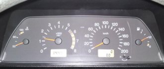
During self-diagnosis of a VAZ 2115 with an injector, only numbers or flashes that code the error will be shown on the instrument panel. When reading trouble codes from an electromechanical instrument cluster, it is necessary to record the number of flashes and calculate error numbers from them. Their purposes can be deciphered using a special list. Most of these faults can be resolved independently by replacing failed sensors.
When performing diagnostics, it is necessary to take into account that the number on the screen may indicate two summed errors. For example, 9 indicates the presence of two faults - numbered 1 and 8.
| Numeric combination | Decoding |
| 1 | ECU problem |
| 2 | Incorrect data from the fuel level sensor |
| 4 or 8 | Network power problems |
| 12 | Malfunction of the error lamp circuit in the instrument cluster |
| 13 | No signal from lambda probe |
| 14 or 15 | Incorrect data from temperature sensor |
| 16 or 17 | Problems with the network power supply, it is necessary to check for short circuits |
| 19 | Motor shaft position sensor error |
| 21 or 22 | Throttle sensor error |
| 23 or 25 | Incorrect operation of the intake air temperature sensor |
| 24 | Speed sensor faulty |
| 27 or 28 | No signal from lambda probe |
| 33 or 34 | No air flow data available |
| 35 | Idle speed control sensor is faulty |
| 42 | Ignition control circuit problem |
| 43 | Knock sensor failure |
| 44 or 45 | Violation of the composition of the mixture |
| 51 or 52 | ECU memory errors |
| 53 | Error in CO setting sensor (installed on cars without converter) |
| 54 | Octane corrector sensor (installed on cars without a converter) |
| 55 | Violation of the composition of the mixture |
| 61 | Failure of the lambda probe |
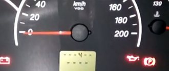
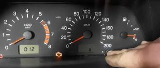
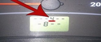
An example of error 14 appearing on the panel
Table of decoding codes for flashes calculated during diagnostics.
| Error code | Flash combination | Decoding |
| 12 | Long-pause-two short | Diagnostic circuit malfunction |
| 14 | Long-pause-four short | Engine temperature sensor malfunction |
| 15 | Long-pause-five short | Likewise |
| 16 | Long-pause-six short | Abnormally high mains voltage |
| 17 | Long-pause-seven short | Abnormally low mains voltage |
| 19 | Long-pause-nine short | Crankshaft position sensor failure |
| 21 | Two long, pause, one short | Incorrect data from the throttle position sensor |
| 22 | Two long, pause, two short | Likewise |
| 24 | Two long, pause, four short | Problem with the speed sensor |
| 27 | Two long, pause, seven short | Lambda probe failure |
| 28 | Two long, pause, eight short | Likewise |
| 33 | Three long, pause, three short | Air flow meter needs to be checked |
| 34 | Three long, pause, four short | Likewise |
| 35 | Three long, pause, five short | Idle speed outside the tolerance range |
| 43 | Four long, pause, three short | No signal from knock sensor |
| 51 | Five long, pause, one short | Memory error in block |
| 52 | Five long, pause, two short | Error in controller |
| 53 | Five long, pause, three short | Memory error in block |
| 61 | Six long-pause-one short | No signal from the immobilizer |
The data obtained allows you to quickly find the faulty element and eliminate the cause of the error.
We recommend: Popping sounds in the muffler - how to fix it yourself?
The video from the Garage channel shows diagnostics on a VAZ 2115 using a scanner and laptop.
Controller errors
The most common controller errors encountered during diagnostics are listed in the table.
| Program error number | Decoding |
| R 0030-0038, 0141 | Malfunction of the lambda probe heating system |
| R 0102 and 0103 | Incorrect signal from the air supply sensor |
| R 0112 and 0113 | Error in data from intake air temperature sensor |
| R 0115-0118 and 0217 | Problems detecting engine temperature or overheating |
| R 2122 and 2123, 0222 and 0223, and 2138 | Incorrect signal from the gas pedal and throttle position sensor |
| R 0171-0172 | Incorrect mixture parameters |
| R 0201-0204 | Faulty injectors (each cylinder has its own code) |
| R 0261-0272 | Problems with injector control |
| R 0130-0134 | Problems with the functioning of the lambda probe before the converter |
| R 0136-0140 | Problems with the functioning of the lambda probe after the converter |
| R 0300 | Multiple misfires |
| R 0301-0304 | Cylinder misfires |
| R 0326-0328 | Knock sensor failure |
| R 0351-0352, 2301 and 2304 | Monitoring the operation of ignition coils |
| R 0422 | Failure of the neutralizer |
| R 0691-0692 and 0693-0694 | Failure of the first and second cooling fan start relays |
| R 0560-0563 | Problems with power supply |
| R 0627-0629 | Indicates incorrect operation of the fuel pump control circuit |
| R 1602 | Malfunction in the engine parameters control controller |
Reset errors
To do this, go to the error viewing menu, press the odometer reset key and wait a few seconds. The number 0 will light up on the screen - the error has been reset. In this case, data about problems is stored in the unit’s memory and must be deleted. If left, the “Check Engine” light will light up in the instrument cluster.
To reset the error, do the following:
- Turn on the ignition.
- Open the hood and remove the negative terminal from the battery. Wait about a minute, connect the wire back and close the hood.
- Turn off the ignition.
- Turn on the ignition again and start the engine. The Check Engine light may come on briefly and then go off.
If the symbol remains illuminated, there is an ongoing problem with some sensor or wiring in the vehicle. It can only be found out using a special scanner. It is necessary to conduct additional diagnostics to determine the problem node. Then carry out repairs and clear any existing errors using a computer diagnostic program for the ECU.
Resetting errors on cars with an electromechanical instrument cluster is carried out by disconnecting the negative terminal of the battery from the on-board network for 10 seconds. The ignition must be turned off.
As stated above, without deciphering error codes, diagnosing a vehicle is meaningless. Therefore, deciphering combinations should also be given attention. Especially if you don’t want to pay a lot of money to specialists at the service station for this. So, let's start with the combinations that appear during self-diagnosis of the car.
How to diagnose the error?
It is important to know
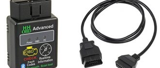
There are two options for diagnosing a VAZ car - testing using the instrument panel and using a computer. The second option is considered more accurate, but its implementation will require a special program and a cable for connecting to the diagnostic connector.
Checking using a computer is done like this:
- The diagnostic wire is connected to the laptop. Its second end must be connected to the OBD2 connector in the Lada car. The location of this block differs depending on the car model; this nuance must be clarified in the service manual.
- A diagnostic program is launched on the computer, which allows you to decipher error codes. To start the test, press the corresponding button.
- The diagnostic process begins. Depending on the utility, the program can separately check the operation of the engine, transmission or electronics.
- After the test is completed, combinations of faults will appear on the computer screen that need to be deciphered. Depending on the program, a description of the error may also be displayed immediately.
Diagnostics using the dashboard is performed as follows:
- The car owner sits in the driver's seat and presses the daily mileage reset button on the odometer.
- The key is inserted into the lock and scrolled to the “ACC” position.
- The daily mileage reset button is released. The arrows on the speedometer, tachometer, and sensors will begin to quickly move from the minimum position to the maximum.
- The odometer key is pressed and released. An inscription with the software version will be displayed on the instrument cluster screen.
- After the third press of the odometer key, combinations of faults will appear on the screen.
Video: diagnosing a VAZ using the dashboard
The CarFance channel in its video showed in detail the process of testing a Lada car using a control combination.
Which one should I install?
Which oxygen sensor for the VAZ-2114 is worth buying? About the second generation there are two types of sensors. Old cars with 1.5 engines and an eight-valve cylinder head have sensors with code 0 258 005 133.
And models that were produced after 2004 were equipped with elements with code 0 258 006 537. What is noteworthy is that both lambda probes are produced by Bosch (at least that’s what it says on the label). The cost of a new sensor is about 1.2-1.8 thousand rubles.
How to reset the error?
Good to know
You can delete the error code from the memory of the VAZ control unit by disconnecting the terminal from the battery.
The reset procedure is performed as follows:
- The vehicle's ignition system is activated, but the power unit does not start.
- The engine compartment of the vehicle opens. Using a wrench, loosen the screw that secures the terminal clamp on the negative output of the battery.
- After about one minute the contact is reconnected.
- The engine compartment of the car is closed, the ignition system in the car is turned off.
- The car engine is starting. If the “Check” indicator remains lit on the dashboard, it should disappear on its own after a few kilometers.
Problems and encodings do not match
Sometimes error codes indicate known working components. This is a big problem for VAZ-2115 owners, so we will give examples of why this could be:
- the sensors themselves failed, not the units;
- low-quality fuel was poured into the tank (often leading to the occurrence of combination P0300);
- clogged fuel and air filters need to be replaced;
- changes in the subtleties of engine operation due to the use of unauthorized software for the on-board computer;
- replacement of parts with non-conforming ones;
- failure of the computer diagnostic system.
If you do not have the necessary firmware to operate gas equipment, you will not be able to use the car at all. The computer will block it. It is interesting that the VAZ-2115 power unit is capable of digesting any gasoline, but its sensors are more sensitive to the quality of the fuel. Perhaps the manufacturer was in a hurry when installing a modern system on the “fifteenth”. Reviews from most motorists say exactly this.
The cost of diagnosing errors for VAZ at service stations in Moscow and St. Petersburg
Approximate prices for computer diagnostics:
| City | Company name | Address | Phone number | Price |
| Moscow | North Motors | St. Dubninskaya, 83 | +7 | 2500 rub. |
| Silver elephant | St. Pyalovskaya, 7 | +7 | 3500 rub. | |
| Saint Petersburg | Automagic | St. Uchitelskaya, 23 | +7 | 2000 rub. |
| ClinliCar | Bolshoy Sampsonievsky Ave., 61k2 | +7 | 3000 rub. |
Fault 1602
Most often, car enthusiasts encounter the P1602 encoding. It means problems in the electrical circuit of the vehicle. This error may be associated with the computer, broken wiring, or a malfunction of the computer itself.
The vehicle condition monitoring system constantly tests the battery, so often on a frosty morning the owner of a VAZ-2115 may encounter an unpleasant surprise on the display in the form of an error. With it, the car simply will not start. If you often encounter problems with P1602, then it makes sense to try to fix the problem by changing the firmware. Remember that you should only use official versions.
However, although the above situation occurs frequently, it is not the only reason for the indicated code to appear on the display. It is worth checking the car for the following problems:
- low voltage in the network (additionally, the sensors may also respond with errors);
- dead battery (in this case, the functions of the VAZ-2115 are blocked);
- short circuits in the wiring or broken wires in one of the sections of the circuit;
- increased load on the electrical circuit (occurs when installing powerful speakers and a subwoofer);
- problems with the generator, in which it produces insufficient current, which leads to constant use of the battery;
- failure of power grid measuring sensors.
Often the failure of various sensors leads to the fact that when you try to start the engine, the computer issues a dozen different codes. A malfunction in the operation of the on-board system itself also manifests itself. Moreover, in some cases, the car may simply not start, since errors do not simply transmit information, but prevent the engine from starting.
The best way to protect against the appearance of unnecessary codes is to change the on-board electronics software. However, it is important to use only official versions. Poor-quality firmware can easily destroy the entire electrical system of the VAZ-2115. It can send strange commands to all controllers at once.
System diagnostic methods
There are two ways to identify errors in Grant and its analogues. Both methods have clear advantages and disadvantages.
Self-diagnosis of Lada Granta
The principle of the method is to use standard systems installed on the machine. The procedure does not require connecting additional equipment or studying complex instructions. To perform the check, just follow a simple sequence of actions:
- simultaneously hold down the daily mileage reset button located on the dashboard and turn the key in the lock cylinder to position 2;
- if everything is done correctly, the machine will go into self-diagnosis mode, all the arrows will make a full revolution and the indicators will light up;
- Use the button on the steering column wiper position switch to select the required option;
- Information about the firmware version appears first in the list. By clicking on the positions further, you can see the required error combination.
Note!
If, when switching to self-diagnosis, any indicators do not light up, their circuits must be checked first.
The disadvantage of this method is the low accuracy of the indicators. The display displays compressed information about the breakdown, which can only indicate the direction from which to start looking for the problem. In the most popular versions of ECU firmware, network errors are noted as:
- The specified Lada Granta error code indicates the presence of a critical power surge in the on-board network. In 90% of cases it indicates a short circuit or damage to electrical appliances.
- You need to check the float sensor in the gas tank and its circuit. There may be a short circuit or damage to the sensor.
- The motor has overheated or the antifreeze temperature sensor has broken.
- Failure in the power supply circuit of the ambient temperature meter.
- Additionally, it indicates overheating of the power plant or incorrect operation of the thermostat. Indirectly affects more complex faults such as cylinder head gasket breakdown.
- The pressure in the fuel rail has dropped critically. You will need to check the pumps and the condition of the injectors. A popular error in the first generation Grant engine.
- If the brakes have failed or the pads have worn out badly, diagnostics of the modules is necessary.
- Severe voltage drop in the on-board network. There may be problems with the battery.
If “E” is displayed on the device, this indicates that the firmware is not working correctly.
Computer diagnostics
The next method involves connecting special equipment to the machine. The bottom line is this:
- there is a special connector under the dashboard;
- a laptop with the program is connected to the terminal via a special connector;
- device pairing begins;
- After establishing a stable connection and reading information from the BC, Lada Granta error codes will be displayed in the software window.
If everything is done correctly, special codes are displayed on the monitor. Moreover, each part of the code speaks of its own circuit.
Beginning (letter)
- P – the integrity of the electrical wiring is compromised or the sensors are damaged;
- C – probably the breakdown is in the suspension units, chassis;
- B – problems with the internal equipment of the car;
- U – resynchronization of several interconnected circuits is observed.
The following are standard notations:
- 0 – failure in the OBD 2 module;
- 1/2 – enterprise code (what this is is known only to the car manufacturer);
- 3 – malfunction of spare wiring parts.
The next part indicates the serial number of the on-board circuit section where the breakdown is located:
- 0 – exhaust cleaning device;
- 1 – motor air supply system;
- 2 – fuel lines, pumps and injectors;
- 4 – control devices;
- 5 – malfunctions or disruption in the operation of additional systems;
- 7/8 – transmission, chassis.
Next comes another two-digit number - the last part of the index points directly to the system where there is a problem.