Description of the occurrence of error P2120 P2122 P2123 P2125 P2127 P2128 P2138
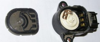
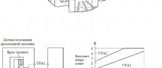
The APP sensor is installed on the accelerator pedal bracket and has 2 circuits: VPA (main) and VPA2 (auxiliary). The sensor is non-contact. In order to obtain accurate signals even under extreme driving conditions, such as very high and very low speeds, this sensor is designed using the Hall effect. The output voltage of the sensor supplied to the VPA and VPA2 contacts of the ECM varies in the range from 0 to 5 V in proportion to the angle of rotation of the accelerator pedal (throttle valve). The VPA circuit signal indicates the actual accelerator pedal angle (throttle angle) and is used to control the engine. The VPA2 circuit signal conveys the status of the VPA circuit and is used to test the APP sensor.
The ECM monitors the actual accelerator pedal angle (throttle valve angle) using signals VPA and VPA2, and controls the throttle valve based on these signals.
Diagnostic Trouble Codes P2120 P2122 P2123 P2125 P2127 P2128 P2138
| No. Errors | Error detection condition | Faulty area |
| P2120 | VPA voltage changes rapidly beyond the upper and lower fault thresholds for more than 0.5 seconds (1 trip detection logic) |
|
| P2122 | VPA voltage is less than 0.4 V for more than 0.5 seconds with the accelerator pedal fully released (1 trip detection logic) |
|
| P2123 | VPA voltage is at least 4.8 V for more than 2.0 seconds (1 trip detection logic) |
|
| P2125 | VPA2 voltage changes rapidly beyond the upper and lower fault thresholds for more than 0.5 seconds (1 trip detection logic) |
|
| P2127 | VPA2 voltage is less than 1.2 V for more than 0.5 seconds with the accelerator pedal fully released (1 trip detection logic) |
|
| P2128 | Conditions (a) and (b) persist for at least 2.0 seconds (1 trip diagnostic logic): (a) VPA2 voltage is greater than 4.8 V (b) VPA voltage is 0.4-3.45 V |
|
| P2138 | Conditions (a) or (b) persist for at least 2.0 seconds (1 trip diagnostic logic): (a) The voltage difference between VPA and VPA2 is less than 0.02 V (b) The VPA voltage is less than 0, 4 V, and VPA2 voltage is no more than 1.2 V |
|
NOTE:
If one of these error codes is detected, check the APP sensor voltage by accessing the following menu items on the handheld scan tool: Powertrain / Engine and ECT / Data List / Accelerator Position No.1 and Accelerator Position No.2.
| Faulty area | Accelerator Position No.1 Accelerator pedal is not depressed | Accelerator Position No.2 Accelerator pedal is not depressed | Accelerator Position No.1 Accelerator pedal is depressed | Accelerator Position No.2 Accelerator pedal is depressed |
| Open circuit in VCP circuit | 0-0.2 V | 0-0.2 V | 0-0.2 V | 0-0.2 V |
| Open or short circuit to ground in the VPA circuit | 0-0.2 V | 1.2-2.0 V | 0-0.2 V | 3.4-5.0 V |
| Open or short circuit to ground in the VPA2 circuit | 0.5-1.1 V | 0-0.2 V | 2.6-4.5 V | 0-0.2 V |
| EPA circuit open | 4.5-5.0 V | 4.5-5.0 V | 4.5-5.0 V | 4.5-5.0 V |
| Normal condition | 0.5-1.1 V | 1.2-2.0 V | 2.6-4.5 V | 3.4-5.0 V |
NOTE:
- The accelerator pedal position is expressed as voltage values.
- PA means accelerator pedal.
How to Troubleshoot or Reset Trouble Code P2127
Some suggested steps to troubleshoot and fix error code P2127:
- Read all stored data and error codes using an OBD-II scanner. To find out when and under what circumstances error P2127 appeared.
- Clear the error codes from your computer's memory and test drive the vehicle to see if P2127 appears again.
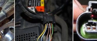
- Visually inspect the electrical wires and connections related to the throttle position sensor “E” for looseness or damage.
- Compare the readings of other throttle position sensors using a scanner, and replace the faulty sensor if necessary.
- Clear the error code from your computer memory again and test drive the vehicle to find out if the problem is resolved.
Emergency function
When any of the error codes P2120, P2121, P2122, P2123, P2125, P2127, P2128 and P2138 are detected, the ECM enters emergency mode. If one of the 2 sensor circuits is faulty, the ECM uses the remaining circuit to calculate the accelerator pedal position, thus allowing the vehicle to move. If both circuits fail, the ECM considers the accelerator pedal to be released. As a result, the throttle valve closes and the engine idles. Emergency operation continues until a normal condition is detected and the ignition is turned off.
Additional comments for troubleshooting error P2127
To properly diagnose the P2127 error code, you will need a multimeter, as well as an advanced OBD-II scanner, which allows you to not only read stored error codes, but also view data from various sensors in real time. It should also be noted that diagnosing and eliminating this error can take quite a lot of time and effort, so if this code is detected, it is best to seek help from a qualified specialist who has the necessary diagnostic equipment.
Symptoms of malfunction
The main driver symptom of P2138 is the MIL (Malfunction Indicator Light) illumination. It is also called Check engine or simply “check light”.
They can also appear as:
- The “Check engine” warning light on the control panel will light up (the code will be stored in memory as a malfunction).
- Other related trouble codes may also be present.
- Jerking/misfire at idle or under load.
- The engine stalls or has trouble starting.
- The engine cannot be accelerated and the throttle response is unresponsive.
- Poor speed gain.
- Loss of engine power due to slow throttle response.
Error P2138 is quite serious, as when it appears, problems with the engine and handling of the vehicle can occur. To avoid dangerous situations on the road, it is recommended to eliminate this error as soon as possible.
Reasons for the error
Code P2138 may mean that one or more of the following problems have occurred:
- Failure of the throttle position sensor or accelerator pedal (TPPS).
- Open throttle position sensor circuit or poor electrical connection.
- The throttle position sensor wiring harness is shorted to ground or another wire.
- The throttle body cover is warped, preventing the gears from rotating properly.
- The electronic throttle body is faulty.
- Corroded MAP or TPS connector.
- Throttle return spring stuck.
- Sometimes the cause is a faulty PCM.
Diagnosis and problem solving
Carefully check the Throttle Position Sensor (TPS), wiring connector and wiring for opens, etc. Repair or replace as necessary to resolve P2127.
Check the voltage at the TPS (see your vehicle's service manual for more information). If the voltage is too low, this indicates a problem. Replace the sensor if necessary.
If recently replaced, the TPS may need to be adjusted. On some vehicles, installation instructions require proper alignment or alignment (see repair manual for details).
If there are no symptoms, the problem may be intermittent and cleaning the code may temporarily resolve it. In this case, you should definitely check the wiring to make sure that it is not rubbing, worn out, etc.
Description and meaning of error P2127
This diagnostic trouble code (DTC) is a generic powertrain code, which means it applies to OBD-II equipped vehicles. While general, specific repair steps may vary depending on the make/model. Code P2127 means that the vehicle's computer has detected that the TPS (throttle position sensor) is reporting too low voltage. On some vehicles, the lowerlimit is 0.17 - 0.20 volts (V). E stands for a specific circuit, sensor, or area of a specific circuit. Did you configure it during installation? If the signal value is less than . 17Vthen PCM sets this code. This can be an open path or a short path in the signalcircuit. Or you may have lost 5 volts of reference voltage.
Error p2127 Lada Granta
It was/has become
With the introduction of Euro-4 toxicity standards, car manufacturers were required to tighten the emission toxicity system even more, but the available software methods have already exhausted their capabilities. The electronics remained unable to fill the cylinders with air, which was entirely dependent only on the driver, while the system had to frantically adjust and try to smooth out the negative effect of his, not always correct, actions. This is how the electronic throttle was born; with its help, many problems were solved, the main one of which was obtaining complete control over the filling of the cylinders with air.
On cars with carburetor engines, the driver, by pressing the accelerator pedal, practically controls the process of supplying the air-fuel mixture to the engine cylinders. Each movement of the pedal through a cable or lever mechanical drive is proportionally transmitted to the carburetor throttle valve. Rotation of the throttle valve around its axis causes a change in the flow area of the diffuser. A change in the flow area leads to a change in the speed and volume of air flow passing through the diffuser. The speed and volume of air flow directly determines the amount of fuel entering through the carburetor nozzles, and therefore the composition of the air-fuel mixture entering the engine cylinders. With the advent of direct fuel injection systems, control of the mixture formation process was transferred to electronics. The driver has only one function left - controlling the position of the throttle valve, and therefore controlling the filling of the cylinders. Electronics, based on the position of the throttle valve and the amount of incoming air, controls the ignition timing and the amount of fuel supplied to the cylinders.
In this case, the electronics takes into account a whole set of parameters: engine speed, temperature, exhaust gas composition, knock sensor readings. Without the ability to control the filling of the cylinders, the electronics are not always able to provide optimal engine torque corresponding to the pedal position set by the driver. During transient conditions, especially when the throttle valve is opened quickly, it is necessary to increase the amount of fuel to ensure the desired mixture composition with increasing air flow. Naturally, the amount of harmful substances in the exhaust gases also increases. The point of the electronic gas pedal is not to get rid of the mechanical connection between the pedal and the throttle valve, replacing it with an electric one. The sensor on the pedal sends only a signal about the position of the pedal to the electronic engine control system (ECM). The ECM calculates the optimal engine torque corresponding to the pedal position and implements it. The electronics itself changes the position of the throttle valve, controlling the filling of the cylinders, setting the desired ignition timing, and regulating the amount of fuel. Naturally, this takes into account external factors - speed, engine speed, temperature - and specified restrictions on the composition of exhaust gases. The engine always operates in optimal mode. The result is reduced fuel consumption and reduced emissions of harmful substances. The electronic pedal allows you to ensure toxicity in accordance with the strict Euro-4 and Euro-5 standards, which cannot always be achieved with a mechanical throttle drive. The starting characteristics of the engine during cold starts are also improved.
Many drivers who are already familiar with the electronic pedal complain about the delay, especially when pressing the gas pedal sharply. In reality there is no delay. The electronics reacts to pedal movement instantly. But the acceleration occurs smoothly, without jerking. It is this smooth increase in speed that is perceived as a delay. The speed of acceleration depends on the ECM calibrations of the specific vehicle model. It is different on different cars.
With the advent of E-GAS (electronic pedal system) modifications in 2010, the list of original sensors and actuators (list at the bottom) used on VAZ cars and working with the new M74 and Bosch M17.9.7 controllers has expanded.
First of all, this is, of course, the actual electronic (without using a cable) accelerator pedal assembly (MPA) located on a bracket near the driver’s right foot, which consists of two independent pedal position sensors that transmit information to the controller about the current position of the gas (accelerator) pedal.
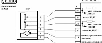
The MPA uses a position sensor with two potentiometers, which are independently powered by a 3.3 V controller and driven by a pedal lever. Two independent springs between the pedal arm and the housing create a return force. Receiving an analog electrical signal from the MPA, the controller generates a signal to control the throttle position.
To avoid interference with each other, both sensors are powered separately, from different terminals of the controller, with a calibrated voltage of 3.3V. Since there are special requirements for the reliability of this signal, the controller constantly monitors the sensors and, at the slightest deviation in power supply or mismatch of output signals, sets errors (P2122-P2123, P2127-P2128, P2138).
Having received an analog signal from the electronic accelerator pedal (AMP) module, the controller generates signals to control the throttle valve.
Many people use “Spur” or analogues for “agility”, but the essence is the same - “it only changes the signal from the throttle position sensor”, “It has little benefit: only a subjective improvement in traction at partial loads. In fact, the driver can achieve a similar effect if he is more decisive with the right pedal. In a word, this is a device for those who are too lazy to step on the gas.”
Car owners are trying to combat the phenomenon of engine throttling by installing certain devices with big names in the throttle pedal sensor circuit - Gas Pedal Booster, Electronic Throttle Corrector, Pedal Booster, Jetter, etc. and so on. These devices replace the signal from the pedal sensors with a higher voltage potential. For example, pressing the pedal by 20%, we have an output voltage from the sensor (in reality there are two sensors - for reliability) 2 volts, but the device will replace the signal with 3 volts and the ECU will think that the pedal is pressed 40% and supply a large dose of fuel and issue permission for more torque. The same effect can be achieved by simply pressing the pedal for most of its travel. These devices seem to increase the sensitivity of the pedal and nothing more. But the torque limit will not go away; the damper will open just as slowly and smoothly, depending on the software algorithm. This is some cunning of the manufacturers of these devices.
Electronic pedal Author: Alexander Smirnov 02/25/2011 Since January of this year, LADA cars began to be equipped with an electronic accelerator pedal. Is it good or bad? Today, almost all imported cars are equipped with such an electronic pedal, primarily those that meet the Euro-4 and Euro-5 requirements for exhaust gas toxicity. On cars with carburetor engines, the driver, by pressing the accelerator pedal, practically controls the process of supplying the air-fuel mixture to the engine cylinders. Each movement of the pedal through a cable or lever mechanical drive is proportionally transmitted to the carburetor throttle valve. Rotation of the throttle valve around its axis causes a change in the flow area of the diffuser. A change in the flow area leads to a change in the speed and volume of air flow passing through the diffuser. The speed and volume of air flow directly determines the amount of fuel entering through the carburetor nozzles, and therefore the composition of the air-fuel mixture entering the engine cylinders. With the advent of direct fuel injection systems, control of the mixture formation process was transferred to electronics. The driver has only one function left - controlling the position of the throttle valve, and therefore controlling the filling of the cylinders. Electronics, based on the position of the throttle valve and the amount of incoming air, controls the ignition timing and the amount of fuel supplied to the cylinders. In this case, the electronics takes into account a whole set of parameters: engine speed, temperature, exhaust gas composition, knock sensor readings. Without the ability to control the filling of the cylinders, the electronics are not always able to provide optimal engine torque corresponding to the pedal position set by the driver. During transient conditions, especially when the throttle valve is opened quickly, it is necessary to increase the amount of fuel to ensure the desired mixture composition with increasing air flow. Naturally, the amount of harmful substances in the exhaust gases also increases. The point of the electronic gas pedal is not to get rid of the mechanical connection between the pedal and the throttle valve, replacing it with an electric one. The sensor on the pedal sends only a signal about the position of the pedal to the electronic engine control system (ECM). The ECM calculates the optimal engine torque corresponding to the pedal position and implements it. The electronics itself changes the position of the throttle valve, controlling the filling of the cylinders, setting the desired ignition timing, and regulating the amount of fuel. Naturally, this takes into account external factors - speed, engine speed, temperature - and specified restrictions on the composition of exhaust gases. The engine always operates in optimal mode. The result is reduced fuel consumption and reduced emissions of harmful substances. The electronic pedal allows you to ensure toxicity in accordance with the strict Euro-4 and Euro-5 standards, which cannot always be achieved with a mechanical throttle drive. The starting characteristics of the engine during cold starts are also improved. Many drivers who are already familiar with the electronic pedal complain about the delay, especially when pressing the gas pedal sharply. They say: “You press the gas, but the engine is silent and doesn’t pick up speed right away.” In reality there is no delay. The electronics reacts to pedal movement instantly. But the acceleration occurs smoothly, without jerking. It is this smooth increase in speed that is perceived as a delay. The speed of acceleration depends on the ECM calibrations of the specific vehicle model. It is different on different cars. Drivers of some cars report a long delay, while in others they hardly notice it. An electronic gas pedal is a useful and necessary thing, its advantages are undeniable. And it’s easy to get used to the smooth increase in speed - and you simply stop paying attention to it. With the tightening of toxicity standards, part of the last opportunity - traction control - was taken away from drivers, transferring it to electronics.
Electronically controlled throttle body
The throttle pipe is designed to regulate the air flow entering the internal combustion engine when operating as part of an electronic engine control system. The type of throttle pipe depends on the controller with which its electrical parameters are coordinated
On VAZ family cars, two types of throttle pipes (DP) are used: 21116-1148010-00 (used with M74 controllers) and 21126-1148010-00 (used with Bosch M17.9.7 controllers)
Original intake manifolds are designed for installing these ducts on cars.
The opening and closing of the throttle valve is carried out using an electric drive based on signals from the controller. It is strictly prohibited to force the valve to open mechanically. The current throttle position is also determined by two independent throttle position sensors.
Engines 21126, 11194 with ECM M17.9.7: pipe 21126-1148010-00
Engines 11183 with ECM M74: pipe 21116-1148010-00
On engines 11183, pipe 21116-1148010-00 is installed on the intake module using an o-ring 21116-1008617 and secured with four M6 bolts 21116-1008612 with washers 21116-1008613, bolt tightening torque 8...12 N.m.
Engine intake module 11183.
On engines 21126 and 11194, the pipe 21126-1148010-00 is installed on the studs of the intake module using an o-ring 2112-1008636-10 and secured with three M6 nuts 1/58962/11 with washers 1/11977/73, the tightening torque of the nuts is 5...8 N .m.
Engine intake module 21126, 11194.
Mass Air Flow Sensor (MAF)
The main feature of systems with E-GAS was the possibility of using a frequency-type . The mass air flow sensor is designed to determine the air flow entering the internal combustion engine. In such sensors, depending on the measured air mass, it is not the voltage in the ADC channel that changes, but the frequency of the output signal. The M17.9.7 controller (21214-1411020-20) provides a separate 5V supply voltage for this sensor (contact X1-37), on M74 (11183-1411020-01/02; 51/52) the mass air flow sensor is powered together with the throttle position sensors ( X1-K1).
The type of mass air flow sensor depends on the type of controller with which its electrical parameters are matched. The type of mass flow sensor used depends on the type of controller with which its electrical parameters are matched. For 16th grade. engines 21126, 11194 and Niva 4×4 21214 are designed for MAF 21700-1130010-00, for 8-cl modification 11183 (with ECU M74) sensor 11180-1130010-00 is designed.
Bottom line The electronic throttle is used not so much to improve and optimize the dynamic and economic characteristics of the car, but to achieve the required Euro standards. This is where artificially created problems arose with a slow response to pressing the gas pedal, freezing of speed when releasing the gas, increased fuel consumption and even more reduced dynamic characteristics of the car.
https://www.drive2.ru/l/1637412/
When buying a new car, namely after “breaking in” (2000 km), when all the components have gotten used to it, it is mandatory
On which cars is this problem most common?
The problem with code P2127 can occur on different machines, but there are always statistics on which brands this error occurs more often. Here is a list of some of them:
- Audi
- BMW
- Chery
- Chevrolet (Chevrolet Aveo, Cruz)
- Citroen
- Daewoo (Daewoo Gentra)
- Dodge (Dodge Caliber, Ram)
- Ford (Ford Mondeo, Focus)
- Honda (Honda Accord, Civic)
- Hyundai (Hyundai Santa Fe)
- Kia (Kia Rio)
- Lifan
- Mitsubishi (Mitsubishi Outlander)
- Nissan (Nissan Almera, Qashqai, Sunny, Tiida)
- Opel
- Peugeot
- Skoda (Skoda Octavia)
- Subaru
- Toyota (Toyota Corolla)
- Volkswagen
- VAZ 2114
- Lada Granta, Kalina, Niva, Priora
- UAZ Patriot
With fault code P2127, you can sometimes encounter other errors. The most common are the following: P2106, P2122, P2126, P2138, P1229, P1551.
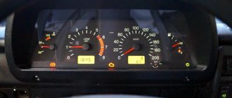
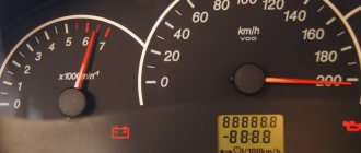
Self-diagnosis error codes:
2 Excess voltage in the on-board electrical network
3 No signal in the circuit from the fuel level sensor
4 No signal from the internal combustion engine temperature sensor
5 The signal from the sensor measuring the air temperature outside the car is not detected
6 Raising the engine temperature above the permissible level
7 Critically low oil pressure in the engine lubrication system
8 Brake fluid leak or failure of the system's electronic components
9 Excessive reduction in battery voltage
E Data error in EEPROM block memory

