It is important to know!
Every motorist should have a universal device for removing scratches on a car of any color. The effect is visible within 10 minutes, and the action of RENUMAX will pleasantly surprise you with its simplicity and effectiveness. Read more >>>
Purpose of additional starter relay
There is an opinion that on cars with an old ignition switch (manufactured before approximately 2003, (the key is illuminated in the form of a green ring, and not a separate LED), there is no additional starter relay. However, on some new cars with ECU January 7.2 and higher, such an additional The starter relay is installed from the factory.
Here is what is written about this in the service manual for VAZ 2110, 2111, 2112:
- The controller controls the on/off of the additional starter relay depending on the crankshaft speed and the time the starter cranks the engine.
- After setting the ignition key to the “Starter” position and the crankshaft rotation speed not exceeding 500 min1, the controller sends a signal to an additional relay and thus turns on the starter.
- After being turned on, the starter will work until the ignition key is in the “Starter” position for no more than 20 seconds, provided that the “correct” password has been received from the immobilizer and the crankshaft speed has not increased to 500 min1. This prevents the starter from turning on when the engine is running and its overheating during prolonged cranking.
In other words, why do you need an additional starter relay :
- To protect the starter from accidental (due to wear, prolonged starting) sintering of contacts in the ignition switch;
- In order to turn off the power to the starter when the engine has started, but the key, for some reason, continues to be in the “starter” mode;
- Relieves the load on the ignition switch contacts.
How to check the additional starter relay , is it installed in the “ten”?
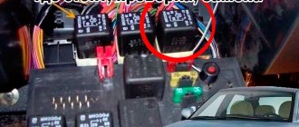
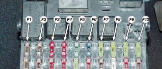
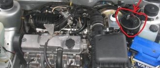
- First, check the presence of an additional starter relay in the mounting block. This relay is mounted and is indicated by an arrow in the photo.
- Secondly, you can check its operation as follows: turn the starter in the cylinder purging mode, after 12-13 seconds the starter should turn off automatically.
Installing an additional starter relay
By the way, stores have a kit of additional starter relays for self-installation. For example, a kit from Avtoelektronika, which contains everything necessary for installation, however, the circuit included in the kit turned out to be unfinished. For the additional relay to operate correctly, it was necessary to add a 1A direct current diode to the circuit (1N4000-1N4007 or the Russian analogue KD243(A-Zh)).
In order to get rid of constant fines from cameras, many of our readers successfully use Special Nano Film for license plates. A legal and 100% reliable way to protect yourself from fines. Having familiarized ourselves and carefully studied this method, we decided to offer it to you.
In order to get rid of constant fines from cameras, many of our readers successfully use Special Nano Film for license plates. A legal and 100% reliable way to protect yourself from fines. Having familiarized ourselves and carefully studied this method, we decided to offer it to you.
Looking for a starter relay
If any devices on the car fail, then first of all you need to check the relay or fuse in the circuit. Therefore, as soon as after diagnosing them, it will be possible to draw conclusions about the problems as a whole.
As you know, on a VAZ-2112, even when the engine is not running, all devices are powered directly from the battery, and when it is started, the energy comes from the generator. And when the current in the circuit increases or there is a short circuit, the fuse simply blows, and a relay is provided for the most powerful devices.
Photo of the starter relay in the fuse box
In order to get to the fuse and relay box in which the starter relay is installed, you need to find the cover on the underside of the dashboard. Then, press the locking button and fold it down.
The starter relay is marked with a red arrow
Replacing the old element with a new one must be done in the reverse order of removal.
Please note that in various vehicle configurations, additional relays can be installed on top of the unit, which are intended for certain groups of devices. But the starter relay is always installed second, on the right.
Notes
Categories:
- Switching devices
- Relay
- Relay protection
- Automation
Wikimedia Foundation. 2010.
See what “Relay” is in other dictionaries:
relay - , constant; Wed An automatic device that closes or opens electrical circuits in response to certain phenomena to which it is designed to respond. Switch relay. Electromagnetic relay. ◁ Relay, oh, oh. R oe ... ... Encyclopedic Dictionary
relay - uncl. Wed relais < relayer change, replace. unit Traveling from one station to another on horseback. We go to one station, then another, a man gets into the stagecoach, perhaps a very respectable one, but without a nose, the Englishwoman suffered for two, three relays and began to beg... Historical Dictionary of Gallicisms of the Russian Language
relay - a device for automatic switching of electrical circuits based on an external signal. It consists of a relay element (usually with two stable states) and a group of electrical contacts that close (or open) when the state changes... ... Encyclopedia of Technology
RELAY - A sensitive electromagnetic device used in a telegraph. Dictionary of foreign words included in the Russian language. Chudinov A.N. 1910. RELAY is a very sensitive electromagnetic device through which. the current of the telegraph line passes and... ... Dictionary of foreign words of the Russian language
RELAY - (French relais) a device for automatic switching of electrical circuits based on an external signal; consists of a relay element (with two stable equilibrium states) and a group of electrical contacts that close (or open) when... ... Big Encyclopedic Dictionary
RELAY/ - (re), uncl. Wed (French relais) (physical tech.). An electromagnetic device that controls the action of something. signaling or other apparatus, machine or network by closing or opening an electrical circuit. Cathode relay (radio) is the same as cathode... ... Ushakov's Explanatory Dictionary
relay - , uncl. Wed (French relais) (physical tech.). An electromagnetic device that controls the operation of some signaling or other device, machine or network by closing or opening an electrical circuit. ❖ Cathode relay (radio) is the same as... ... Ushakov's Explanatory Dictionary
RELAY - RELAY, several Wed (specialist.). A device for closing and opening an electrical circuit. Electromagnetic river | adj. relay, oh, oh. Ozhegov's explanatory dictionary. S.I. Ozhegov, N.Yu. Shvedova. 1949 1992 ... Ozhegov's Explanatory Dictionary
relay - noun number of synonyms: 11 • barorele (1) • hydrorelay (1) • kipp relay (1) • ... Dictionary of synonyms
relay - for controlling electrical circuits; relay A relay action device designed to make changes in electrical circuits (usually control, signaling and communication circuits) ... Polytechnic terminological explanatory dictionary
- Control and protection relays. Volume 1. Control relay (+ CD-ROM). Control and protection relays belong to the class of low-current switching devices and are used in electrical devices as a control and protection element. Control relay and… Read more Buy for 2652 RUR
- Control and protection relays. Volume 2. Protection relays. Directory. Control and protection relays belong to the class of low-current switching devices and are used in electrical devices as a control and protection element. Control relay and… Read more Buy for 1520 UAH (Ukraine only)
- Control and protection relays. Volume 2. Protection relays. Directory. Control and protection relays belong to the class of low-current switching devices and are used in electrical devices as a control and protection element. Control relay and… Read more Buy for 1469 RUR
Other books on request “Relays” >>
Lada 2110 PhiX › Logbook › Additional, starter unloading relay VAZ 2110
Hi all! I’ll tell you about a very useful modification that will be useful for owners of elderly VAZ 2110. Many ten-year-olds have encountered a problem when, in hot weather, a hot engine does not respond to the movement of the key. The starter does not turn and you have to go under the hood with a screwdriver and make a direct connection to the contacts. In the case when the starter is working (in my case it is completely new), the culprit for this trouble may be the contact group of the ignition switch. Over time, the contact group in the ignition switch wears out or the current collector contacts burn out. This problem is successfully solved by installing an additional unloading relay. By the way, such a relay is installed on many cars from the factory.
To install this relay we will need: 4-pin relay with a metal ear (30-40A); 80r Wires 1.5 sq. mm; about three meters -80r relay block - 1 piece; 20r Flat male connector - 1 piece; Flat female connector - 1 piece; Ring tips - 2 pcs. Electrical tape, heat shrink, corrugation.
Let's put this whole thing together according to the following scheme.
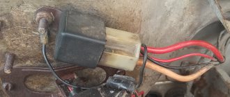
The relay needs to be protected from moisture, for this I used thick heat shrink, in which I completely covered the relay block.
After assembly, I check the relay by connecting it to the LBP.
Pay attention to the laboratory power supply, the ammeter shows the current that the relay consumes. The current is only 0.12A and it is this current that will flow through the contact group of the ignition switch. For comparison, the pull-in current according to different sources is from 10 to 30A! Most often we are talking about 20-25A, where 20A is the current of the pull-in winding and 5 amperes of the holding winding.
Obviously, such currents will not be to the liking of the ignition switch contact group. The relay solves this problem perfectly.
I carried out another experiment, turned the voltage towards a decrease, the relay operates down to 7V, at 6V it no longer works, but this is quite enough, because the retractor will not work even at 8 volts.
We connect the wiring to the starter.
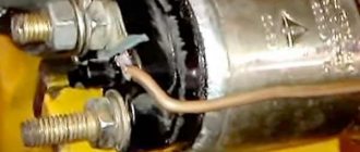
We pull off the red wire from the flat terminal of the traction relay and tightly insert the “folder” with the wire from the new relay into the connector of this wire. This wire now powers the coil of the new relay. We connect wires with ring lugs to the battery terminals.
We put the wire from contact 30 of the new relay with the “mother” onto the freed contact of the traction relay. Through this wire, the plus goes to the traction relay coil.
Setup procedure
The minimum holding current of the thyristor (in this case on the KU101E thyristor) was 3.32 mA, therefore the current supplying thyristor VS1 through resistors R7 and R8 (Fig. 1) of the base circuit of transistor VT2 should be higher and is set by selecting these resistors.
In the case when the thyristor has a larger holding current, especially with a transistor switch VT2 of p-p-p conductivity, an additional ballast resistance is connected, it is possible with a construction resistor according to the principle of the circuit in Fig. 4.
What is meant here is that in a pnp transistor, unlike a pnp transistor, when the thyristor is open, current flows through the emitter-base circuit and through the open thyristor, the value of which depends on the current-limiting resistor.
Next, we charge capacitor C1. When relay K1 turns on, we close the circuit of capacitor C1, the capacitor will discharge. Relay K1 should turn off quickly, this should be repeated several times. In Fig. Figure 3 shows an alternative version of an electronic relay with improved capabilities.
The thyristor is turned on according to the current of the control electrode with a current greater than the holding current, and turned off - according to the current below the holding current. The device differs from the previous circuit in that the base of the transistor switch VT2 is connected between the anode of the thyristor VS1 and the cathode of the diode VD2, and the control electrode of the thyristor VS1 is connected to the anode of the diode or is connected to the emitter of the transistor VT1 through resistor R7.
Other ways to connect the control electrode are possible, for example, through a diode, zener diode, capacitor individually or mixed, or supplemented with a resistor. Thus, the base of the key of transistor VT2 is cut off from communication with “-”, including through the control electrode of thyristor VS1.
The following parameters were set on the KU101E thyristor during repeated tests: the holding current was 3.32 mA; at a lower current the thyristor was turned off. The minimum total current at which the thyristor opened again was 4.2 mA.
The voltage difference between turning off and turning on the thyristor at the common point of the emitter VT1 was 0.7 V. (It is worth noting that this principle can be used in tracking devices.) The holding time at the same ratings is the same as the circuit in Fig. 1, and the error is The device operates as follows.
When you press the SB1 button, the charging circuit of capacitor C1 is turned on. The positive voltage at the base will open transistor VT1. The current on the control electrode will cause the thyristor VS1 to open, the anode of the thyristor will accept a low potential, and the base of the transistor VT2 will receive a negative bias, which will completely open the emitter-collector junction of the transistor and turn on relay K1.
When the SB1 button is released, capacitor C1 will slowly begin to discharge when the minimum voltage at the emitter of transistor VT 1 reaches 1.5 V, and with a total current of less than 3.32 mA, the thyristor VS1 switches to the closed state.
The base of transistor VT2 will move to a positive bias and the transistor will switch to the closed state, relay K1 will turn off. In Fig. Figure 7 shows the printed circuit board of the electronic relay.
Rice. 7. Printed circuit board (method 2).
Starter fuse (relay) VAZ 2110
Very often I get a question via email! Which fuse is responsible for the start function on a VAZ 2110 car and where is it located.
I would like to answer it right away - the fuse responsible for the starter on the VAZ dozen does not exist. But there is a starter relay and it is this that very often burns out and fails
What is it used for?
This protective device is necessary, just like a circuit breaker. However, this device has a different purpose - to monitor voltage.
Overvoltage in the network is a common cause of failure of expensive equipment, the repair and replacement of which costs a pretty penny, since failure from overvoltage is not covered by warranty. And as a rule, such surges last a few seconds until the protection at the substation is triggered; this is quite enough for the electronics in the house to fail. Look at how many devices you have plugged in, even if you don’t use them, at the moment, they are all a potential threat.
To avoid this, a voltage relay has been created that monitors the state of the electrical potential in your apartment around the clock, and will instantly de-energize the network in the event of an abnormal change.
Pay attention to the single-phase relay RN-104 volt control from the manufacturer Novatek Electro. Easy to set up and operate, it will guard the electrical network of your home or apartment
Below we will look at the design and operating principle of a voltage control relay.
How to replace the central locking fuse on a VAZ 2110 with your own hands
Great, now let's move on to the step-by-step instructions for replacing the starter relay on a VAZ 2110 with your own hands:
- Press the fuse box cover switch and lower it down.
- We take a Phillips screwdriver and unscrew the screw securing the latch and pull it out.
- Now remove the fuse box from the cover and turn it over
- Now we disconnect all the plugs with wires and take out the fuse box.
- Using pins, we remove the failed fuse responsible for the cigarette lighter, recall its designation in the R7 diagram and replace it with a new one.
- We put everything back together in reverse order.
The most common breakdowns
One of the most common problems is the loosening of the power cable tip. Simply tighten it and check all the other nuts at the same time. The second popular reason for the failure of this unit is considered to be oxidation of contacts. If you notice a problem at an early stage, then just clean the contacts and the unit will work properly. If cleaning doesn't help, you will need to replace them.
Scheme
Oxide often occurs on the winding, making it impossible to block. You can try to clean the winding, but experienced motorists recommend replacing the relay immediately, this way you will be able to drive your car much longer without problems.
Another probable cause of problems with starting the engine is a break in the retractor power supply circuit. You will have to find them and fix the problem. Find the broken wires and place new ones in their place. Upon completion of work, check the relay power circuit again. One way to check the functionality of a disassembled relay is to check it with an ohmmeter. To do this, you need to place the probes of the device on the turns of two windings.
Sometimes it is enough to replace the anchor. This must be done when it operates slowly or is idle. These signs directly indicate a malfunction of the anchor itself. It will be quite difficult for a car enthusiast with little experience to identify problems with this element.
Repairing a relay is more expensive than replacing it, so the easiest way is to immediately replace the faulty part. This will save your time, because it is unknown whether repairs, which are often very labor-intensive, will help. An attempt to restore the unit is fraught with danger - if the relay is repaired incorrectly, you can be left without a car for a long time, since engine starting will be blocked. In this case, you will need to carry out more complex repairs, which cannot be carried out without the participation of specialists.
You can install the starter relay on the VAZ 2110 yourself
Those people who have a VAZ 2110 have certainly encountered a situation where the starter did not turn after the key was turned, and some clicks are heard, which indicate that the retractor relay is working. In such a situation, the question immediately arises: where is the VAZ 2110 starter relay located and how to find it faster. This question is also relevant when tuning a VAZ 2111.
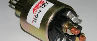
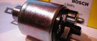
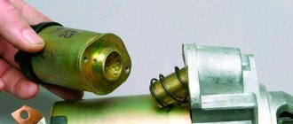
But we have interesting news for you: the VAZ 2110 simply does not have a starter relay. There is a solenoid relay, to which the positive contact is supplied from the ignition switch. The relay is installed on the starter, its size is 2 times smaller than that of the starter, and it is round in shape.
Next, we will highlight some popular malfunctions that usually arise in the VAZ 2110, related to the VAZ 2110 starter relay and the starter; by the way, a lot of things are used in the VAZ 2115, so by tuning this car, many problems can be avoided.
Installation process
- We prepare the wiring. We crimp the connectors.
- The new VAZ 2110 starter relay must be mounted under the hood in a place so that it is definitely not flooded with water from puddles and rain. Many specialists install the relay on the stud of the washer reservoir.
- We bring the wire from the relay to the starter and connect it to the place of the red wire (it is with the “dad”). This is the connection point for the traction relay. This way we energized the coil of the new relay.
- We put a new wire with an 8 (mm) ring connector onto the positive terminal of the starter and tighten it tightly with a bolt. This wire goes to pin 87 in the new relay. I hope the VAZ 2110 starter connection diagram is clear to everyone.
- From the new relay on pin 30 we pull a wire with a “female” connector to the starter, to the place where the traction relay is connected.
- We connect the lead from pin 85 on the new relay to ground.
- We cover all wiring with a corrugated sleeve and thoroughly insulate it so that the wiring and contacts are not exposed to moisture.
- We do a test drive.
That's it, the additional VAZ 2110 starter relay (diagram attached) has been successfully installed.
Basic starter malfunctions
The traction relay does not operate after the ignition key has been turned, and the armature does not rotate.
In this situation, it may be due to the following possible problems:
- the battery is broken or discharged, the solution to this problem is to buy a new battery or charge it;
- the positive contacts have oxidized - you just need to clean them;
- it happens that an interturn short circuit occurs on the winding of the traction relay - to correct this situation, you need to install a new relay;
- the circuit that powers the traction relay has broken - you need to check the wires for integrity, and whether they have become disconnected from the circuit?
- contacts “30” and “50” do not close - you just need to change the contact part of the ignition switch;
- The traction relay armature does not work well - you need to remove it and disassemble it, there may be a lubrication problem.
After turning the key, the starter does not start, the armature rotates slowly, and a click is heard in the traction relay.
This situation may arise due to previously similar situations:
- the battery is discharged or disconnected - you need to check and correct the situation;
- the winding of the traction relay is shorted or broken - you also just need to change the relay;
- the ends of the wires have seriously succumbed to oxidation - they need to be checked and cleaned, starting with the battery.
After turning the key, the starter armature spins, but the flywheel does not spin..
This situation arose due to the fact that:
- the freewheel is slipping - you need to diagnose the starter at the stand and replace the clutch if it is faulty;
- The gears on the gearbox are worn out - you just need to replace them.
The starter makes a lot of noise when the armature is spinning.
This problem arose because:
- The liners on the armature or drive shaft bearings have served their service life - you just need to replace the parts that have failed;
- the starter is not secured properly, and the cover could have broken - you just need to secure it or change it;
- the gears on the gearbox, flywheel crown or drive have failed - you just need to change them, or immediately replace the non-functioning parts entirely.
- the gear is constantly engaged with the flywheel; if the clutch on the shaft splines is stuck, it is possible that the armature of the traction relay is stuck - to solve this problem, you need to lubricate the splines with oil. And if the traction relay is stuck, then you need to either change it or use certain methods to get rid of the jam.
How to check
After turning the ignition key to the “ON” position, the main relay is turned on and power is supplied to everything except the starter system of the vehicle. At this moment, a buzzing sound will be heard in the area of the gas tank - the operation of the fuel pump. Further turning of the key will close the contacts of the starter relay and start it. When you repeatedly try to turn the starter, such a sound will most likely not be heard, and this is not a malfunction. The fuel line is filled with gasoline, and the pressure sensor will not allow the pump to start when the engine is not running.
To check the serviceability, we use a 12-volt lamp with a current consumption of no more than 0.25 A. We connect pieces of insulated copper wire to the contacts. Using a more powerful lamp may damage the ECU chips.
We check the presence of power at the control contacts of the relay coil - terminals 85 and 86, alternately touching the negative contact of the battery. If there is power at one of the contacts, the lamp will flash, which means the control circuit is working properly. If you connect the lamp directly to the control terminals of pair 85-86, the next time you turn on the ignition, the lamp will light up for 15-20 seconds. Otherwise, you need to check the serviceability of the wiring leading to the terminals and the corresponding fuses, or proceed to check the operation of the computer.
If at the first stage of the test the serviceability of the control circuits of terminals 85 and 86 is established, at the second stage of the test we check for the presence of +12 V on leg 87 of the fuel pump control relay relative to ground. The lamp does not light up - check the circuit fuse and wiring. If there is voltage at the terminal, we close terminals 87 and 30 with a jumper, thereby simulating the situation when the relay is activated, as a result, the fuel pump should start and start working. If the result is negative, we will try to start the pump directly and touch one of the wires of the control lamp to the fuel pump terminals in turn, and attach the second wire to the body ground. If the lamp lights up, most likely there is a problem with the performance of the pump itself, otherwise you need to check the power wiring of the fuel pump.
One of the possible malfunctions of the fuel pump relay is sticking of contacts 86 and 30, due to which the fuel supply will continue even after the engine is turned off. The cause is usually the melting of the plastic of the holders and subsequent melt soldering of a pair of contacts. In this case, the relay must be replaced at the first opportunity.
The video describes in detail how to check the fuel pump:
- What malfunctions are prohibited from operating a car?
- How dual-zone climate control works
- How to make a winch from a starter with your own hands: video instructions and drawing
- Why do you need an air filter in a car?
Replacing the VAZ 2110 starter relay on your own
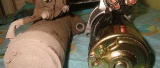
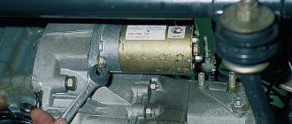
All drivers know that without a starter, the car not only won’t move, it won’t even start. It drives the crankshaft. In this case, the shaft is accelerated to a certain frequency. As soon as the desired frequency is reached, the engine will start. One of the starter components is a two-winding traction relay. Replacing the VAZ 2110 starter relay is a mandatory procedure, because without the correct operation of this mechanism, the vehicle will not move. On a VAZ 2110, replacing the starter relay can be done on your own.
What is a relay for?
Replacing the starter relay on a VAZ 2110
The traction relay ensures that the drive gear starts. Starting occurs in clutch with the gear mechanism of the crankshaft flywheel. It also provides power to the starter motor. When the starter is turned on, energy begins to be transferred from the battery. The energy path passes through the ignition switch.
This is interesting: The starter spins for a long time when starting
VAZ 2110 additional starter relay
In this way, power is supplied to each winding of the traction relay. Windings have two types:
As soon as the process of closing the relay contacts takes place, the retractor winding is turned off. A working relay has a voltage limit that should not exceed 8 V. The temperature during this process should not exceed 25 degrees Celsius. If the voltage when starting the relay exceeds this indicator, then you should pay attention to the drive and the traction relay itself. They may become damaged or stop working. The traction relay can be visually examined. Perhaps the breakdown can be seen with the naked eye, but the starter will have to be dismantled and disassembled.
VAZ 2110 starter lock relay
Diagnostics using ODB-2 scanner
The general technical condition of the car can always be checked using a personal diagnostic car scanner. Of the options available on the market, we recommend paying attention to the Korean-made scanner Scan Tool Pro Black Edition. This model is perfectly compatible with most domestic and foreign cars.
A special feature of the device is comprehensive car diagnostics. Unlike analogues, this auto scanner is capable of diagnosing not only the engine, but also ABS, gearbox, transmission, airbag, air conditioning system, etc. The device is also great when used as an on-board computer: in real time it displays speed, revolutions, readings from all available sensors, oil pressure, temperature and much more.