1200 rub. for the photo report
We pay for photo reports on car repairs. Earnings from 10,000 rubles/month.
Write:
The most basic function of the generator is to charge the battery and power the electrical equipment of the engine.
A generator is a mechanism that converts mechanical energy into electrical energy. The generator has a shaft on which a pulley is mounted, through which it receives rotation from the engine crankshaft.
Interactive image of the generator circuit. Works on mouseover
A car generator is used to power electrical consumers, such as the ignition system, on-board computer, car lighting, diagnostic system, and it is also possible to charge a car battery. The power of a passenger car generator is approximately 1 kW. Car generators are quite reliable in operation because they ensure uninterrupted operation of many devices in the car, and therefore the requirements for them are appropriate.
How to connect a battery charging light
A constantly charged battery will not only ensure reliable starting of the car engine, but will also maintain its trouble-free operation for a long time. Hence the need to constantly monitor the battery charge level. There are different methods - operational methods that do not require removing the battery from the vehicle, and testing using additional monitoring devices. The article describes operational control methods that should be used periodically.
What to consider when choosing a new battery
According to the passport, the battery is designed for 3-5 years of active use (in reality it turns out to be less). Therefore, over time, it becomes necessary to buy and connect a VAZ 2107 battery instead of a failed one.
When purchasing a new battery, you should consider a number of parameters and characteristics. Battery type: serviced and maintenance-free. The first option allows you to check and replenish the electrolyte level. This makes it possible to use the battery longer.
The next question is: what power will the battery on the VAZ 2107 be most efficient. Batteries with a capacity of 50–60 Ah are suitable for this model. However, given that modern cars are equipped with energy-intensive equipment, it is better to opt for more capacious batteries. In addition, carburetor VAZ models require more powerful batteries - they consume more energy when starting. In terms of dimensions, the VAZ 2107 requires power supplies with dimensions of 242*175*190 mm. The vast majority of samples available on the market fit them.
When choosing a battery, you should also take into account the place of residence of the owner of the “Seven”. For those who live in the south, you can purchase a less powerful battery. Northerners are advised to prefer a battery with a higher capacity: in the cold, the car starts with high energy consumption.
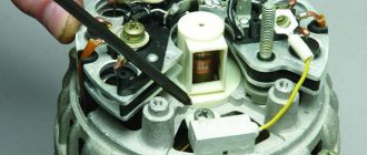
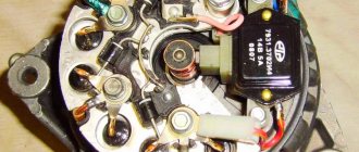
Generator device
The design of a car generator implies the presence of its own rectifier and control circuit. The generating part of the generator, using a stationary winding (stator), generates three-phase alternating current, which is then rectified by a series of six large diodes and the direct current charges the battery. Alternating current is induced by the rotating magnetic field of the winding (around the field winding or rotor). Next, the current is supplied to the electronic circuit through the brushes and slip rings.
Generator structure: 1.Nut. 2. Washer. 3.Pulley 4.Front cover. 5. Distance ring. 6.Rotor. 7.Stator. 8.Back cover. 9.Casing. 10. Gasket. 11.Protective sleeve. 12. Rectifier unit with capacitor. 13.Latch holder with voltage regulator.
The generator is located at the front of the car engine and is started using the crankshaft. The connection diagram and operating principle of a car generator are the same for any car. There are, of course, some differences, but they are usually associated with the quality of the manufactured product, the power and the layout of the components in the motor. All modern cars are equipped with alternating current generator sets, which include not only the generator itself, but also a voltage regulator. The regulator equally distributes the current in the excitation winding, and it is due to this that the power of the generator set itself fluctuates at a time when the voltage at the power output terminals remains unchanged.
The principle of operation of a car generator
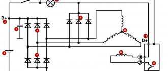
Connection diagram for the VAZ 2110-2115 generator
The alternator connection diagram includes the following components:
- Battery.
- Generator.
- Fuse block.
- Ignition.
- Dashboard.
- Rectifier block and additional diodes.
The principle of operation is quite simple: when the ignition is turned on plus through the lock, the ignition goes through the fuse box, light bulb, diode bridge and goes through a resistor to minus. When the light on the dashboard lights up, then the plus goes to the generator (to the excitation winding), then during the process of starting the engine, the pulley begins to rotate, the armature also rotates, due to electromagnetic induction, electromotive force is generated and alternating current appears.
Next, the diode passes plus into the rectifier block through a sine wave into the left arm, and minus into the right arm. Additional diodes on the light bulb cut off the negatives and only positives are obtained, then it goes to the dashboard assembly, and the diode that is there allows only the negative to pass through, as a result the light goes out and the positive then goes through the resistor and goes to the negative.
The principle of operation of a car DC generator can be explained as follows: a small direct current begins to flow through the excitation winding, which is regulated by the control unit and is maintained by it at a level of slightly more than 14 V. Most generators in a car are capable of generating at least 45 amperes. The generator operates at 3000 rpm and above - if you look at the ratio of the size of the fan belts for the pulleys, it will be two or three to one in relation to the engine frequency.
To avoid this, the plates and other parts of the generator rectifier are partially or completely covered with an insulating layer. The heat sinks are combined into a monolithic design of the rectifier unit mainly by mounting plates made of insulating material, reinforced with connecting bars.
What else to check
- Voltage regulator;
- Generator rectifier unit;
- Diodes;
- Generator for broken windings;
- Generator brush assembly;
- Contacts on the terminals of the generator, mounting block.
A malfunction of any of these elements leads to the fact that the charging system is inoperative and the VAZ 2107 battery is not charged.
Let's continue... Diodes are checked with a test light or multimeter. If one of them is broken, the entire rectifier will have to be replaced.
To check the stator winding you need the same device. The resistance between the fasteners of the rectifier unit is measured. If there are no contacts between them, you need to replace either the winding or the entire generator.
The generator itself often fails due to wear on the brushes. To check them, you need to remove the brush assembly and measure the length of the elements. If it is 5 mm or less, the brushes must be replaced.
Almost all of the above system components are replaced when they fail, since they cannot be repaired. Only some of the generator problems can be repaired, but this can only be done by a qualified auto electrician.
The worst thing is if problems with recharging occur while on the road. Without recharging the battery, it will eventually run out completely. And even if you manage to find the cause of the breakdown and eliminate it, you will no longer be able to start the engine with the starter. It will be possible to start a VAZ-2017 with a dead battery only from a tug or pusher.
Generator connection diagram for VAZ 2107
The VAZ 2107 charging scheme depends on what type of generator is used. To recharge the battery on cars such as VAZ-2107, VAZ-2104, VAZ-2105, which have a carburetor engine, you will need a G-222 type generator or its equivalent with a maximum output current of 55A. In turn, VAZ-2107 cars with an injection engine use a generator 5142.3771 or its prototype, which is called a high-energy generator, with a maximum output current of 80-90A. It is also possible to install more powerful generators with an output current of up to 100A. Absolutely all types of alternating current generators have built-in rectifier units and voltage regulators; they are usually made in the same housing with brushes or are removable and mounted on the housing itself.
The VAZ 2107 charging circuit has minor differences depending on the year of manufacture of the car. The most important difference is the presence or absence of a charge indicator lamp, which is located on the instrument panel, as well as the method of connecting it and the presence or absence of a voltmeter. Such circuits are mainly used on carburetor cars, while on cars with injection engines the circuit does not change, it is identical to those cars that were manufactured previously.
Generator set designations:
- “Plus” of the power rectifier: “+”, V, 30, V+, WAT.
- “Ground”: “-”, D-, 31, B-, M, E, GRD.
- Excitation winding output: Ш, 67, DF, F, EXC, E, FLD.
- Output for connection to the serviceability lamp: D, D+, 61, L, WL, IND.
- Phase output:
- Output of the stator winding zero point: 0, MP.
- Output of the voltage regulator for connecting it to the on-board network, usually to the “+” of the battery: B, 15, S.
- Voltage regulator output for powering it from the ignition switch: IG.
- Voltage regulator output for connecting it to the on-board computer: FR, F.
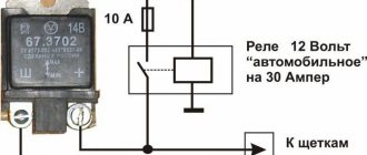
Generator circuit VAZ-2107 type 37.3701
- Accumulator battery.
- Generator.
- Voltage regulator.
- Mounting block.
- Ignition switch.
- Voltmeter.
- Battery charge indicator lamp.
When the ignition is turned on, the plus from the lock goes to fuse No. 10, and then goes to the battery charge indicator lamp relay, then goes to the contact and to the coil output. The second terminal of the coil interacts with the central terminal of the starter, where all three windings are connected. If the relay contacts close, then the control lamp lights up. When the engine starts, the generator generates current and an alternating voltage of 7V appears on the windings. Current passes through the relay coil and the armature begins to attract, and the contacts open. Generator No. 15 passes current through fuse No. 9. Similarly, the excitation winding receives power through the brush voltage generator.
Why is control dangerous?
An incandescent lamp is an electrical product that requires careful handling. Therefore, it is installed in lamps that are permanently attached to building structures or have a stable base, for example, in a tabletop version.
The control is portable and easily damaged. She can:
- explode from increased tension;
- slip out of the hands of an electrician, fall and break (often while connected);
- make a short circuit;
- cause a person to be exposed to electric current.
Experienced electricians have tried to take these risks into account and adopted various technical tricks to increase their own safety. But they are all prohibited by modern rules.
Possibility of explosion
Technical background
When connected to voltage, the resistance of the filament changes according to a nonlinear law. At the initial moment, transient processes occur briefly, and then the nominal operating mode is established.
This is explained by the fact that tungsten in a cold and heated state has different electrical resistance. Let's consider this using the example of a popular 60-watt light bulb. It consumes a current of 0.27 amperes, and its filament has a resistance of 815 ohms.
If you measure its resistance in a cold state, the ohmmeter will show about 59 Ohms. The difference is almost 14 times. This property of tungsten eliminates the need for complex ballast control equipment for the lamp, simplifies the design, but requires consideration during operation.
When the voltage exceeds a linear value of 380, the thread most often burns out, but in a worn-out structure it can explode. There are many examples of such damage. They arise where apartment owners save on protection such as voltage control relays.
Charging diagram for VAZ with injection engines
This scheme is identical to the schemes on other VAZ models. It differs from the previous ones in the method of exciting and monitoring the serviceability of the generator. It can be carried out using a special control lamp and a voltmeter on the instrument panel. Also, through the charge lamp, the generator is initially excited at the moment it starts working. During operation, the generator operates “anonymously,” that is, excitation comes directly from pin 30. When the ignition is turned on, power through fuse No. 10 goes to the charging lamp in the instrument panel. Then it goes through the mounting block to pin 61. Three additional diodes provide power to the voltage regulator, which in turn transmits it to the excitation winding of the generator. In this case, the indicator lamp will light up. It is at that moment when the generator operates on the plates of the rectifier bridge that the voltage will be much higher than that of the battery. In this case, the control lamp will not light up, because the voltage on its side on the additional diodes will be lower than on the side of the stator winding and the diodes will close. If the control lamp lights up while the generator is running, this may mean that additional diodes are broken.
Where to start checking
If the VAZ 2107 battery icon does not light up, the voltmeter gives normal readings, but the battery does not charge, which means there is no (or insufficient) contact at the terminals. Their severe oxidation can cause the voltage from the generator to the battery simply not to flow. Therefore, it is necessary to remove the terminals, thoroughly clean them, as well as the battery terminals, then reconnect the battery to the on-board network and check the functionality of the charging system.
In the case when the voltage on the VAZ 2107 battery is still below normal, you need to measure it at the output from the generator with the engine running. Is there a big difference between the readings on the terminal and on the battery? Try cleaning the contacts and checking the wire connecting the battery to the generator. Broken - requires replacement.
The next element that is checked is the generator drive belt. If it becomes loose, it will slip along the pulley, which is why the generator will not be able to generate the required amount of electricity. And although charging will be carried out (provided the circuit is in good condition), it will not be enough. At the same time, the engine is running, the voltmeter shows the norm. However, if the system is loaded a little more - for example, by turning on the headlights - then the voltage drops sharply. Then, if the battery charge on a VAZ 2107 disappears, this indicates that the tension belt is loose and slipping. The belt should be tightened; if it wears out during operation, replace it. But you can’t overtighten either: excess belt tension puts an overload on the pumps and generator bearings.
The third component of the circuit that is checked during the initial diagnosis is fuse No. 10 (in the fuse box). It is he who is responsible for supplying voltage to the battery: the VAZ 2107 battery charging fuse has blown - the system will not work.
If everything is in order with the terminals, belt, fuse, the reasons for poor charging of the VAZ 2107 battery need to be looked for further.
Built-in charge indicator
This battery indicator, called the "warning light" by many car enthusiasts, is a hydrometer. Its round signal window is located on the top cover of the battery case. The main sensitive element of the float device is a green ball moving along a profile-tube built into the fittings and shaped like a triangle. Its angle is directed vertically upward along the axis of the battery body. The ball moves in an electrolyte environment that fills the internal cavities of the battery compartments.
A light guide tube is laid from the peephole (window) of the battery indicator. Its lower part ends with a conical prism opposite the upper corner of the profile tube, along which the signal ball moves. The light guide is designed for visual control of its position.
A profile tube built into the fittings, a light guide, and an indicator eye lens form a single structure, which is attached to the battery case by means of a screw connection in the eye area. In case of emergency, it can be removed outside (which is highly undesirable).
Checking generator operation
You can check the functionality of the generator in several ways using certain methods, for example: you can check the output current of the generator, the voltage drop on the wire that connects the current output of the generator to the battery, or check the regulated voltage.
To check, you will need a multimeter, a car battery and a lamp with soldered wires, wires for connecting between the generator and the battery, and you can also take a drill with a suitable head, since you may have to twist the rotor by the nut on the pulley.
Basic check with a light bulb and multimeter
Connection diagram: output terminal (B+) and rotor (D+). The lamp must be connected between the main output of the generator B+ and contact D+. After this, we take the power wires and connect the “minus” to the negative terminal of the battery and to the generator ground, the “plus”, respectively, to the plus of the generator and to the B+ output of the generator. We fix it on a vice and connect it.
We turn on the tester in DC mode, attach one probe to the battery to “plus”, and the second one too, but to “minus”. Next, if everything is in working order, then the light should light up, the voltage in this case will be 12.4V. Then we take a drill and start turning the generator, accordingly, the light bulb will stop burning at this moment, and the voltage will already be 14.9V. Then we add a load, take an H4 hologen lamp and hang it on the battery terminal, it should light up. Then we connect the drill in the same order and the voltage on the voltmeter will show 13.9V. In passive mode, the battery under the light bulb gives 12.2V, and when we turn it with a drill, it gives 13.9V.
Generator test circuit
Strictly not recommended:
- Check the functionality of the generator by short circuit, that is, “to spark”.
- It is also undesirable to allow the generator to operate without consumers turned on; it is also undesirable to operate with the battery disconnected.
- Connect terminal “30” (in some cases B+) to ground or terminal “67” (in some cases D+).
- Carry out welding work on the car body with the generator and battery wires connected.
What to do if the electrolyte becomes cloudy
Generator VAZ 2107: operating principle and connection diagram
First, you should use standard prevention methods. That is, add electrolyte as necessary or simply dilute the acid with increased density with special distilled water.
You should also use a charger or simply try to replenish the charge if it drops below the permissible values, due to the active operation of the generator.
When such measures do not help, we have to look for alternative ways out of situations.
The characteristics of the changing electrolyte may vary. Experts distinguish several options:
- gray working fluid in the battery;
- cloudy mixture of acid and water;
- brown electrolyte;
- black liquid.
Each option should now be considered separately, depending on the color.
Grey
In its normal working state, the acid-water mixture has no color, that is, it remains completely transparent.
But it happens that motorists notice changes. This happens in one car battery bank or in all of them at the same time, when the electrolyte is completely painted dark gray.
In this case, the most likely cause will be a strong discharge.
To return the battery to service, it is recommended to drain the old working fluid, and then fill in a new, fresh and high-quality mixture of purified, prepared acid and distillate.
After this, cyclic charging is required. Current and voltage are selected based on the recommendations prescribed by the manufacturer.
Cloudy color
It also happens that cloudy, as if dirty, electrolyte appears in one battery bank or in several battery banks at once.
If a cloudy mixture is detected during testing, this may be due to the use of a low-quality acid-water mixture or the use of tap water poured literally from the tap.
It also happens that turbidity appears in the entire battery, that is, when checking all available cans. In this situation, the problem is more likely to be the low quality of the purchased battery.
To restore the battery's functionality, you can replace the mixture of water and acid, and then follow the charging procedure according to the instructions.
Brown
And in some cases, the acid-water mixture has a brown tint. It is quite easy to distinguish it from a gray or simply cloudy electrolyte.
The main reason that the fluid turns brown is that the battery is overcharged. Or the plates were severely exposed during charging due to a lack of electrolyte.
It is best when the problem is observed only on the side of one can and the brown color is not very saturated. Then the problem can be solved by adding fresh electrolyte.
If the shade is dark enough, you will need to completely change the composition of the acid and distillate used in the entire battery, and then carry out a sequential charging cycle.
Black
Motorists have repeatedly noted that when opening the battery, they noticed black electrolyte in the battery of their vehicle. And here it is logical to ask what to do in such a situation.
An acidic working fluid that has turned black is unlikely to be restored. That is, a complete replacement will be required here.
Blackening of a mixture of acid and water is possible when the plates are destroyed and lead particles accumulate at the bottom of the cans.
It is lead that contributes to such intense coloring.
If blackening is observed in only one of the cans, first try replacing the working fluid there. In some cases, it is actually possible to restore the operation of the device. But this is only allowed in a situation where there is no short circuit between the plates.
Otherwise, you will have to completely change the entire electrolyte or the battery itself with a new one. Shedding of lead-based internal plates is a strong argument and reason to think about buying a new car battery.
Monitoring the battery charging process
To correctly understand the reasons for the unstable operation of the lamp that controls the charging progress of the battery, you need to understand the interaction of the generator and the direct current source. When the engine is running, the battery is constantly charged with a voltage of 13.6 to 14.2 volts. The charging current is generated by the generator. The voltage of the output electricity depends on the speed of the generating device. The higher the speed, the greater the voltage. To limit the voltage within specified limits, a regulator is connected to the rotor winding circuit. It is this that stabilizes the output voltage, which is then supplied to the battery terminals for charging.
If the charging current is constantly supplied within the specified limits to maintain the battery in working condition, the battery charging indicator lamp should not light up. A constant glow of the light indicates that the generator is not working or that the supply wires are broken. The most common cause of generator failure is a weakened or torn drive belt.
Video: car battery charging system
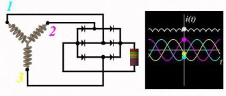
Generator circuit
The operation of the generating device is based on the principle of electric magnetism. Structurally, there are two main parts with the help of which alternating current is produced.
The rotor and stator generate current into the vehicle's on-board network
These are the stator and the rotor. The rotor is driven by a drive belt from the engine crankshaft. The stator is stationary and consists of windings that are attached to the generator housing. Together they form a structure in which the rotor is centrally located inside the stator. There is a gap between them, which allows the rotor to rotate at enormous speed.
Scheme of operation of the generator and connection of the charging control lamp
The stator includes 3 windings that form a three-phase current system. The terminals from the windings are connected to the diode bridge separately, as in the diagram above.
The rotor consists of many electromagnets, which together create a powerful magnetic field. It crosses the stator windings, and a three-phase alternating current is generated in them. The output voltage depends on the speed and is controlled by a regulator, which is built into the system for supplying current to the rotor. To convert alternating current into direct current, a diode bridge consisting of diode rectifiers is used. They only allow current to pass in one direction.
Current is supplied to the electromagnets of the rotating rotor using two copper-graphite brushes in contact with copper slip rings located on the rotor shaft. As the speed increases, the relay-regulator reduces the current in the rotor, thereby reducing the magnetic field.
The battery charging control lamp is connected to a set of diodes that are connected in parallel to each of the three stator windings. This is a separate circuit and the amount of current here is small, but sufficient to light the LED indicator. So, to the light bulb, on one side there is a positive wire from the general network of the charging system, and on the other contact there is a positive wire from the ignition switch. If equal voltage is applied to both sides, the light bulb does not light. If there is no voltage on one contact, the light comes on. If the charging current begins to pulsate or decrease, the light begins to flash or light up with less brightness.
How to find phase and zero
Let us recall the voltage distribution diagram in a three-phase network made using the TN-C grounding system.
During military service, during exercises, I had to practically solve a similar problem in the field conditions of a training ground. It was necessary to find phase and zero in a six-core power cable connected to voltage in order to power the lighting circuit from them.
There was no indicator or measuring instruments. A messenger was sent for the light bulbs, and we made do with an ordinary electric razor and a piece of insulated wire.
The test was carried out in two stages:
- determination of phase ends;
- search for zero.
Measurement of phase voltages
The work proceeded according to the following scheme:
- they hammered a piece of metal into the ground next to the cable;
- they attached one contact of an electric razor plug to it;
- a piece of wire was screwed to the second pin and secured with threads;
- with the free end of this conductor we touched all the cores of the cable in turn;
- We marked the three wires on which the razor motor started working - this is how we identified the phase ends and chose the one where it would be easier to install the subsequent circuit.
DIY battery indicators
The unreasonably inflated price of industrial battery voltage level devices forces motorists who are familiar with the basics of radio engineering and have soldering skills to make these devices themselves. A popular construction set (DC-12 V) with a set of radio components is produced especially for them, on the basis of which you can independently assemble a battery discharge indicator.
The device informs the user when the measured voltage reaches one of three levels determined by the ratings of the circuit elements. If the battery indicator lights up, the appropriate voltage level has been reached.
Reasons why the battery charge light is on
The battery begins to charge from the moment the engine starts running. To do this, the key is inserted into the ignition switch and turned to turn on the vehicle's on-board power supply. When turning further, the starter is turned on and the engine starts. If, when the car engine is running, the battery charging indicator continues to glow brightly or dimly, then the charging current from the generator does not reach the battery. In this case, the entire load of supplying consumers with current falls on the battery.
Video: reasons for the battery not charging
The reasons for the battery light not going off when the engine is running are always related to problems in the generator and on-board network.
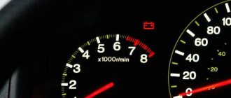
Indicator light
As can be seen from the diagram, the charging system involves a large number of components and each of them can cause poor charging or its absence. To monitor the battery charging process, the car's dashboard is equipped with a control light.
If the system is in good working order, the control signal turns on after the factory. But when the engine enters operating mode, the VAZ 2107 battery charging light does not light up. This means that the battery's energy supply is replenished from the generator. At the same time, the needle on the voltmeter moves to the green sector.
Signs of a battery not charging:
- The VAZ 2107 battery charge arrow twitches.
- The control signal does not go out. In some cases, the VAZ 2107 battery light blinks.
- The voltmeter needle does not go to the green zone after starting the engine.
- When the engine is running, the voltage on the battery should remain around 13.9.
- The permissible deviation in any direction does not exceed 0.3 V. Undercharging of the VAZ 2107 battery within these limits is not yet dangerous.
Why is the battery charging light on?
The battery charging light on the dashboard is designed to monitor the charging voltage of the car's alternator. It is connected in series with the generator excitation winding (on foreign cars until about 2007, and on VAZs until now) from the “+” terminal, that is, the generator relay-regulator “sees” the voltage in the vehicle’s on-board network through it. The light comes on when the ignition is turned on and goes out when the engine starts.
In point 10 - battery charging indicator lamp
How should a light bulb behave when the engine is running?
If the battery is operating normally and the engine is running, the indicator is off.
If the light does not light up or does not go out when you start the engine, it blinks, or lights up at full intensity - this all indicates that the battery is not charging. If you continue to drive, the car will stall after some time, and the electronic units may fail and the battery plates will begin to deteriorate.
Video: the light is constantly on - what to do
Electronic warning lamp relays.
Also, in addition to electromagnetic relays, electronic relays. Of course, these relays are much more reliable. They were widely used in foreign cars produced in the 80s. The principle of these relays is to control the voltage of the on-board network. If the voltage is less than the nominal value, then the control lamp is turned on using an electromagnetic relay or a built-in transistor. On domestic cars, this principle is found on Nivas with a carburetor engine and an imported instrument panel, as well as on other models with imported instrument panels. As a control lamp, such panels used an LED, which was controlled by a unit built into the panel. Such cars were produced in a limited edition.
Source
Common reasons why the battery light is constantly on
These include the following cases:
- The alternator drive belt is loose, worn or torn;
- the fuse has blown in the section of the circuit from the ignition switch to the control light (in this case there is charging);
- contact is broken in the connector blocks of the mounting block;
- malfunction of the relay regulator;
- diode bridge malfunction;
- malfunction in the circuit of additional diodes;
- break in the current supply circuit to the rotor electromagnets;
- poor contact at the battery terminals;
- lack of supply current at the output of the generator;
- the generator brushes are worn out;
- there is no ground on the negative wire.
If the generator is not working on a strong battery, the car will be able to drive for about 2.5–3 hours during the daytime, if you do not turn on the headlights, air conditioning, wipers, or audio system.
The source of many faults in the battery charging system is the generator voltage regulator relay
The light may sometimes come on when the turn signal is turned on.
The most common reason is a malfunction of the diode bridge, poor contact in the rotation fuses, or poor contact in the ground wire of the instrument panel. It is necessary to check the contacts of all terminals on the wires coming from the generator. The problem must be fixed. Indeed, if the generator malfunctions (a break in one of the three diodes), the battery will no longer receive a full charge and after some time will be completely discharged every time the turn signals are turned on and/or off.
The light bulb goes out and burns at full intensity
A battery light that barely burns at half intensity while the engine is running indicates a generator malfunction: the diode bridge or insulation in one of the stator windings is broken. Less commonly, there is a problem with the ignition switch. The key cannot turn all the way due to accumulated dirt. A few drops of WD-40 “liquid key” into the ignition key hole will alleviate the situation. Sometimes it may be necessary to repair the car's electrical wiring and timely diagnose a decrease in the signal to the indicators.
Causes of charging failure and their elimination
If the battery for the VAZ 2106 begins to work less reliably, it is necessary to diagnose the electrical circuit. To do this, you may need a tester (voltmeter or multimeter).
If the VAZ 2106 does not have a charger, the reasons may be the following:
If there is power at the terminal, and the indicator continues to light up on the device, then you should diagnose the contacts in the excitation circuit of the mechanism. To do this, you will need to connect a light bulb between the positive terminal of the battery and the cable connected to output 67 of the regulatory component. You will be able to diagnose the wiring in the relay-generator section, and the check will also show whether the brushes of the mechanism and the windings of the so-called armature are operational. If there is no current here, most likely the problem should be looked for in the rectifier bridge.
The next stage of diagnostics will be to check the functionality of the conductor from the generator unit. For diagnostics, you will need to disconnect the terminal from the mechanism and connect it to a -12 V battery. If the control light is on, this indicates problems with the brushes or a broken armature. If you think that the problem lies specifically in the generator device, then it must be dismantled and a more detailed check and disassembly be carried out. All failed elements must be replaced.
As mentioned above, when the engine is running, the voltage in the network should be from 13.5 to 14.3 volts. If, when driving at low speeds, the VAZ battery charging light comes on and then disappears, while the engine power periodically decreases, in this case you need to check the strap. There is a possibility that it will need to be tightened and adjusted.
Much less frequently, but it still happens that the cause of such a problem is poor contact at the battery terminals. If the voltage level on the battery is higher than necessary, it is necessary to diagnose the contacts in the area from the positive terminal to the regulatory element. If you find that all contacts are normal, then you need to replace the relay itself.
Self-diagnosis of battery charging systems
A set of necessary tools from the following list:
indicator light 12 V;
DIY tool for diagnosing battery charging systems
Procedure for a blinking charge light that does not turn off or goes out
Modern cars have a complex electronic engine control system that does not tolerate an amateurish approach. It is strictly forbidden to check the proper operation of the generator by removing one of the battery terminals. Due to a sharp surge in voltage in the on-board circuit, many elements of the battery charging and engine operation control system can fail. The most reliable, safe, and effective way to check the battery charge is to use a special measuring device - a multimeter.
Control measurement with a multimeter
Although this device can measure many parameters of electric current, in this case we are only interested in one characteristic - voltage. Knowing its value, we can make a conclusion about the technical condition and performance of the generator.
To measure voltage using a multimeter, you need to turn it on in DC voltage measurement mode
- First you need to check the voltage using a multimeter at the battery terminals with the engine off. By comparing the readings of the device with the data, you can judge the degree of discharge of the battery.
- Then the low beam of the headlights and the heating stove are turned on at minimum speed. The voltage at the terminals is measured again. It will decrease, but should not be less than 13.5 V. If the voltage value is less than this value, you need to find out the reason for the abnormal operation of the generator.
If everything is normal with the electrical equipment of the machine, then after 5–10 minutes the electronics will drop the voltage to normal: 13.5–14.0 V
Table: dependence of the degree of discharge on the voltage at the battery terminals
| Battery terminal voltage volts | 11,95 | 12,05 | 12,21 | 12,37 | 12,57 | 12,7 |
| Battery discharge level in percentage | 90 | 70 | 50 | 30 | 10 |
Is it possible to fix the problem?
The main thing is not to miss messages issued by the operating system, which also monitors battery performance. When problems arise with the battery, the OS sends a message about its damage - as a rule, it “crawls out” on the right. If the system does not produce such a message and “believes” that everything is fine with the battery pack, most likely there is a problem with the charger itself.
It is important to keep in mind that if the battery is damaged, it is no longer possible to repair it. In the best case, it will have to be either completely changed or a partial replacement of elements
About laptop battery repair →
The charger can simply be disassembled into parts and tested using a multimeter. Most likely, the wiring has frayed or the contacts have come loose - this problem can be fixed with your own hands. However, if the capacitor burns out, you will have to look for a new, suitable charger.
Operating principle of the built-in indicator
The green ball is made of material with a density of (1.26-1.27) g/cm3. The electrolyte density of a fully charged battery under normal conditions is 1.27 g/cm3. The sensor is subject to a buoyancy force proportional to the density of the liquid in which it is located.
The density of the electrolyte in the battery depends on the degree of its charge. When the battery is discharged, sufficient buoyant force is not created, and the ball, under the influence of gravity, “rolls” to the lowest point of the profile along which it moves. The eye is painted black - the color of the material from which the profile is made.
As the battery charges, the density of the electrolyte increases. Starting from a charge level of 65 percent of the maximum value, the buoyant force of the electrolyte overcomes the component of gravity acting on the ball, and it begins to move along the profile to its highest point. In it, with sufficient lighting, you can see the green color of the eye. “The battery light is on” - this expression can sometimes be heard from the lips of would-be car battery experts.
It is possible that the battery indicator is white. In this case, the surface of the electrolyte can be observed through the peephole. In this case, the operation of the battery must be stopped - topping up with distilled water is required.
Some battery manufacturers place a second red indicator ball in the profile tube. The density of the material from which it is made allows it to occupy the upper position in the profile tube at a reduced electrolyte density (1.23-1.25) g/cm3. In case of insufficient battery charge with this technology, the battery indicator eye will be colored red.
How to reset the “low battery” error
The best advice is to take the car to a service station. There, experienced specialists will do everything safely, quickly, without compromising the delicate electronics of the engine control systems and the safety of the machine. In some foreign car models, this problem disappears over time (if all elements of the charging system are functioning normally). You can solve the problem yourself. To do this, you need to disconnect the negative terminal for three minutes, and then put it back in its place and tighten it well.
You need to know that the battery charging indicator light, by its lighting, blinking and other abnormal glow, signals simple malfunctions. For example, failure of a separate diode, malfunction of the relay regulator, loosening of the drive belt. If a light bulb is detected, it is imperative to find and correct the reason for the lack of battery charge. Or you may soon need to buy a new generator or battery.
Video: the generator does not charge, how to find the fault and achieve proper operation
Unexpected malfunctions in the vehicle's on-board electrical network can lead to serious consequences. It is necessary to respond extremely quickly to the glowing signals of the control system self-diagnosis indicator lights, including the lit battery charging indicator. At the diagnostic station, using the error code, they will quickly identify and correct any malfunction in the charging system of the DC source.
We recommend watching:
Generator diagram VAZ 2110 injector 8 valves Connecting a generator to a car
Replacement and removal of the electric generator
The generator on a VAZ car is removed either for complete replacement in case of failure or to carry out repair work to replace faulty parts. To perform dismantling, prepare a standard set of tools; it is advisable to drive the car into the inspection hole.
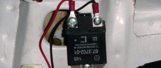
It so happened that my car has a G-222 generator installed (They were installed on cars before 1988, judging by the documentation and some websites). The generator is working and there are no complaints about it, only the battery charge control lamp never came on. The fact is that the generator has pin 15, which is connected to the PC702 charging control relay, which switches the control lamps to the robot. Because of this, I really didn’t want to change the generator to a new one, especially since the old one completely copes with its work, and the light bulb is just the reason for incorrect switching. A light bulb for a car is very important; it can quickly determine whether a belt is broken or a generator is failing, so the question of its operation worried me very much. Once upon a time I already tried to restore a light bulb to a robot, but I didn’t have enough persistence, knowledge or good advice. I think many people will encounter this when they end up on a site that misled me. The site is quite well-known www.autoprospect.ru and I have found the information I need on it more than once, but this time I got caught. What's the matter you ask?! I tell you on the site they offer two connection schemes with a 37.3701 generator and other modifications (We are not particularly interested)
And the circuit for switching on the G-222 generator, which is what I needed.
There was no reason not to trust the eminent site (as it turned out in vain). I called the wiring, took the relay, connected it according to the diagram, and it’s still there... The control light didn’t light up and still doesn’t light up. And I stopped. But then I decided to look for wiring diagrams on other cars and I found a wiring diagram for old and new-style generators on cars 2105-04.
At first glance, as in diagrams 2107, the only difference is in the warning lamp relay. Brown-white in the first case for the generator and in the second for the RS-702 relay. But let's take a closer look. In the diagram for switching on the new generator, the control lamp from the combined instrument goes with an orange wire back to the fuse block, as is the case with both diagrams for 2107. But in the second diagram it also comes white-brown, but it’s not brown that goes out from the lamp, but white-black the wire and it is very important that it goes to the ground. This is the whole nuance and error in the diagram for 2107 and the G-222 generator. I think the whole problem is that the one who drew the drawings for the site in electrical engineering saw two identical drawings at first glance, found the differences as it seemed to him only in the presence of the RS-702 relay, and everything else was a banal “Copy-Paste”, which then led to a headache. When you realize this, the error becomes visible to the naked eye. If you look again at the incorrect diagram given on the site, you can see that when the RS-702 relay is triggered, we get a ring (shown by the red line) and the light bulb in the circuit simply cannot light up since there is no circuit through it; it has the same +12 on both sides from the ignition on.
The correct diagram looks like this
You need to tear off the second wire from the lamp that goes to +12 when igniting and put it on the ground, which is what I did.
The wire on the dashboard does not go very well, after it the orange one is still fed to the indicator of insufficient brake fluid level and I had to cut the tracks.
and make jumpers
A small lyrical digression. Knowing now where I have +12 from the ignition on, I removed the snot from the instrument lighting that went to the yellow-blue wire of the button from the heater stove
and sealed the backlight directly into the tidy
I covered the places of my intervention with tsaponlak to prevent sin and oxidation.
Well, the result is for the sake of what everything was started for, turn the ignition key and enjoy
the light is on as it should be, then we start the engine and it goes out for natural reasons 
And now it’s even more interesting. While I was writing this article for you, after “smoking” this circuit a little more, I came up with the idea of putting the 87th contact of the relay on the ground
With such a connection, the circuit remains operational; for me it’s already too late, but some of you will clearly find it useful. Without changing the dashboard circuit, the orange +12 will go through the light bulb to the brown-white wire and return to the relay; when the PC702 relay is closed, the brown-white wire will touch the ground and the light will light up.
What and how to do is, of course, up to you, but I think my article will help some of you overcome the problem with the light bulb, and save a lot of money on the purchase of a new generator, especially if the old one works well but it does not work well with the car’s wiring. Well, learn a lesson that on trusted sites they write (and draw ) complete nonsense, and for the result you need to consult several sources.
If you find that your VAZ 2107 is not charging the battery, measures must be taken immediately. Continued use of the vehicle may result in battery discharge. You will have to either look for a travel companion willing to tow the car, or call a towing service.
Types of car battery charge indicators
Not many car enthusiasts know the digital values of the battery voltage sufficient to reliably start the car engine. This problem is especially relevant for beginners. On-board computers of modern cars provide the consumer with a large amount of necessary information, including the open circuit voltage of the battery. Analog voltmeters on older cars have a scale that gives information about the battery voltage.
Therefore, there is a need to have indicators that can assess the readiness of the battery to start the engine and communicate the results to the driver in the form of a visual message. The following types of indicators can be distinguished:
- built-in, showing the state of the battery, located directly on the battery case;
- Battery charging indicators produced by third-party manufacturers, which have a scale of permissible and prohibited battery voltage values for starting the start, the charge level expressed as a percentage of its full value.
Built-in batteries have medium and high price scales, mostly of a maintenance-free type. To use indicators from third-party manufacturers, it is necessary to carry out additional work to install them inside the car (in a visible place) and connect them to the battery bus of the car electrical wiring.
Source
We make a battery voltage indicator ourselves: high quality at minimal cost
The quality of battery charging determines how successfully the car will start. Not many drivers monitor the battery charge level. The article discusses such a useful device as a car battery charge indicator: how it works, how it works, instructions and a video on how to make it yourself.
On modern cars with an on-board computer, the driver has the opportunity to obtain information about the battery charge level. Older models are equipped with analog voltmeters, but they do not reflect the true picture of the battery's condition. Battery voltage indicator (VIN) is an option to have operational information about the battery voltage.
Purpose and device
The IN is assigned two functions - to show how the battery is charged from the generator, and to inform about the amount of charge of the car battery. The easiest way is to assemble such a device with your own hands.