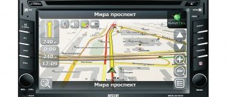
As you know, LPG can significantly reduce fuel costs, especially taking into account the constantly rising prices for petroleum products. Today, the most popular and widespread version is HBO 4. According to the rules, the installation of such equipment must be carried out in specialized service centers, which then issue the documents necessary for registering HBO with the State Traffic Inspectorate.
However, many car enthusiasts, for a number of reasons, are interested in how to install 4th generation LPG with their own hands. Also, especially taking into account the tightening of standards and fines for gas equipment without registration, drivers want to know how to remove the 4th generation gas equipment with their own hands, so as not to incur additional costs.
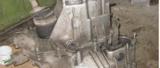
In some cases, owners of gas-powered cars also need to know what the principle of operation of a 4th generation LPG on an injector is, how to adjust a 4th generation LPG yourself, how to turn off the gas on a 4th generation LPG, etc. Next, we will look at the features of installing an LPG 4 on a car, what a gearbox for a 4th generation LPG is and the design of a 4th generation LPG gearbox, how the LPG 4 reducer is installed, and also how to set up such gas-cylinder equipment.
Setting up HBO without an ODB adapter
It’s a shame, but it’s not always possible to read the correct values from ODB.
Sometimes the adapter is not just not compatible with gasoline brains. Let's consider the option of setting up Lovato HBO, when for some reason it is not possible to read the correction coefficients. This method is not accurate; you will not be able to set ideal fuel map coefficients, but the adjustment error will be within acceptable limits.
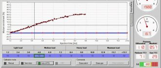
Setting up without ODB is very similar to setting up with an adapter, but in this case, we will not be checking the correction factor, but the gas supply time. This is perhaps the most unstable value and it changes several times per second, one way or another, this is the only thing we can work with now. You need to read the average value of this value, for example, the parameter jumps from 4.5 to 5.0, in this case the average value is 4.75
To correctly adjust the gasoline timing, it is important to drive on the smoothest possible road, with extremely equal speeds; any deviation is critical
Let's start setting up without ODB:
- Gasoline supply is turned on (using a button in the program)
- The driver sets a constant engine speed and precisely maintains it during tuning.
- At these speeds, the average value of the gasoline injection time is read from the Lovato Easy Fast program.
- The gas is turned on (by button in the program)
- The average gasoline injection time is read again.
- The cell under the point on the fuel map is configured. If the gasoline injection time when operating on gas is longer than on gasoline, the cell value increases, if less it decreases. I recommend selecting the entire column and changing it by several units at once. (After highlighting, press the Enter key.)
Gasoline injection time
Gas injection time
Basic parameters of injectors
The development of gas cylinder equipment has provoked the emergence of a huge number of varieties of nozzles. The parameters for the division of dispensers are not several positions, but about ten of the most important divisions. To be more precise, HBO injectors are classified according to:
- Case material (metal or plastic);
- Type of fuel being dosed (propane-butane or methane);
- Coil operating voltage;
- Working pressure and maximum possible;
- Opening and closing times (that is, they can be instantaneous, delayed or customized);
- Electrical resistance of the coil;
- Operating temperature range;
- The outer diameter of the outlet fitting;
- Valve seat diameter;
- Jets available for calibration.
In fact, most of the characteristics of LPG injectors are not required by the average car enthusiast when selecting them. However, for experienced motorists or mechanical aces, each parameter can be extremely important, because the totality of them largely determines the nature of the functioning of a gas engine.
Advantages of fourth generation gas equipment
How to set up a 4th generation Digitronic HBO with your own hands?
instructions from the master! The 4th generation HBO has a number of undoubted advantages compared to its older predecessors. These include:
- Maximum engine efficiency due to the accuracy of formation of the required gas mixture for each operating mode.
- Smooth operation of the power unit, complete absence of “pops” characteristic of early types of gas equipment.
- High degree of environmental friendliness of the engine, meeting Euro 3/4 requirements, due to complete and high-quality combustion of fuel. In this case, the actual reduction in engine power is no more than 2%.
- The versatility of the equipment allows it to be installed on almost all brands of modern cars due to software and hardware compatibility with the EOBD self-diagnosis system.
- Unified block connectors, eliminating equipment installation errors due to personnel inattention and reducing its labor intensity.
- High reliability of equipment operation and affordable price obtained through the use of modern production technologies.
Main problematic issues related to the operation of gas equipment
During the operation of a car with 4th generation gas equipment, a deterioration in its dynamic characteristics may be observed. The reasons for this phenomenon may be:
- malfunction of the gearbox or its incorrect setting, including the dispenser;
- filter clogging;
- reduced temperature of the gas-air mixture (typical for the winter period of operation);
- excessive enrichment of the mixture due to low gearbox temperature.
Something else useful for you:
- How are wheels balanced on a car?
- What is an electronic engine control unit?
- How does climate control work in a car?
If the car takes a long time to start, the reason for this may be:
Video: 4th generation LPG on Suzuki Grand Vitara new
- a malfunction of the gearbox diaphragm or its incorrect setting;
- defect of the flow solenoid valve (mechanical armature jamming or the presence of a short circuit of the turns);
- failure of the electronic unit, expressed in the absence of a permitting signal for gas supply or in the generation of an incorrect signal that does not correspond to the required amount of fuel;
- a malfunction of the starter, which “lowers” the battery voltage during startup, as a result of which the solenoid valves do not operate;
- wear of the piston and cylindrical surfaces of the engine, leading to a decrease in pressure in the cylindrical heads;
- if a vacuum reducer is used, then an additional reason for poor starting may be that insufficient vacuum is created in the inlet manifold due to the need for suction. In such cases, a separate electromagnetic pump can help out, providing forced fuel supply.
Selecting LPG
You can buy everything in one set or separately. Purchasing a kit from a well-known brand will ensure reliable operation of all elements, as they have passed quality certification. Setting up such a kit is much simpler, but its price will be much more expensive.
It is possible to save money by purchasing equipment elements separately, but we should not forget that the choice of components must be approached responsibly, so as not to be disappointed later during operation.
Having everything you need, you can begin installing the 4th generation HBO. Of course, it’s a good idea to entrust the installation to specialists, paying a considerable amount of money. But it’s better to do it yourself, while saving money and understanding the operation of the equipment.
Advantages and nuances of fourth generation HBO
How to connect a mirror with a rear view camera for a car and installation diagram in the cabin
Compared to its predecessors, HBO -4 has undoubted advantages:
- compliance with toxicity standards EURO-3 and higher;
- minimal gas fuel consumption through the use of a microcontroller control system;
- economical engine operation;
- absence of “jerking” and popping noises, which are typical for a mechanical fuel supply system;
- universality of the equipment - installation on all brands of modern cars is allowed, since the electronic unit is fully compatible with the EOBD self-diagnosis system;
- ease of installation - you just need to connect the connectors, so there is no risk of incorrect connection;
- equipment reliability and affordable cost.
At the same time, there are some nuances when operating a gas cylinder installation:
- The useful power of the engine decreases, since the calorific value of gas is much less than that of gasoline. To normalize power, car enthusiasts set the ignition 4-50 earlier. Of course, such a procedure can only be carried out if the engine runs on 95 gasoline;
- a decrease in the temperature of the gas-air mixture - especially typical for the cold season;
- inaccurate gearbox adjustment;
- increased enrichment of the fuel mixture due to low gearbox temperature;
- filter clogging.
System malfunctions can be caused by:
- blocking of the electronic unit - an incorrect signal about gas consumption is received or is absent altogether;
- wear of cylindrical and piston surfaces of the engine;
- inaccurate gearbox adjustment;
- contamination of injectors - repairing LPG gas injectors with your own hands is not recommended, since it is impossible to guarantee uniform operation of the injector. Please note that there are two types of filters - collapsible and non-removable. The first ones do not require adjustment.
Mass air flow sensor device
The internal structure of the sensor is a fine mesh, in the middle of which a platinum thread is stretched. The latter warms up to a temperature of about 700 degrees in a short time. When air passes through it, the thread cools slightly. By how many degrees the filament temperature has dropped in comparison with the reference value, the amount of air passing near it is measured. The output value varies in the range from 0 to 5 Volts. If there is no air flow and the engine is turned off, then the output of the mass flow sensor will be exactly 1 Volt. If you start the engine, air will begin to flow through the mass air flow sensor. The higher its consumption, the greater the voltage will be at the output of the sensor.
Design and operating diagram of gas equipment
Detailed instructions and connection diagram for pioneer car radio
Today, about 70 percent of gas cylinder systems sold in Russia are the 4th generation of gas equipment.
All manufacturers of gas cylinder installations produce identical configurations based on the principle of operation, but there are significant differences in gearboxes, nozzles, and additional controller options. The highest accuracy when supplying fuel is demonstrated by the 4th generation Lovato LPG.
In the 4th version of the gas system, the designers shifted the responsibility for controlling the fuel supply from gas equipment to the gasoline controller of the car.
HBO 4th generation Lovato, the connection diagram is as follows:
- The gasoline electronic control unit receives input pulses from the vehicle’s sensors and controls the fuel supply circuit, that is, it issues commands to gasoline injectors.
- At the moment when the vehicle switches to gas fuel, the ECU program turns off the supply of gasoline fuel, blocking the impulse passing through the wires to the standard injectors.
- The outgoing impulse from the gasoline controller to the standard injectors is modified according to the characteristics of the gas fuel (temperature and compression ratio are taken into account) and is sent to the gas injectors.
The 4th generation Lovato gas equipment scheme has become revolutionary in the way of converting injection cars to alternative, economical fuel.
With the development of the fourth generation, gas devices began to rapidly conquer the market, pushing aside carburetor equipment.
4th generation gas equipment is in greatest demand today. It can be installed on almost any injection vehicles. The connection diagram for Lovato 4th generation LPG to the injector is simple in principle and produces good results during operation.
Controller Features and Functionality
The production of an electronic control unit for gas systems is established in Polsky, whose products have long proven themselves in the gas equipment market.
The device was developed on a 32-bit high-performance processor, has a compact design, assembled in a sealed plastic case, convenient for installation.
Main features of Digitronic Maxi 2/Titan:
- compatible with methane/propane gas equipment
- designed for engines up to 4 cylinders, with distributed fuel supply (paired, phased, asynchronous)
- building a 2D map based on injection time
- work in conjunction with a parameter recorder and an oscilloscope
- Suitable for turbocharged internal combustion engines, also with Valvatronic system
- there is an adjustment for t° and gas pressure
- work with heating of gas injectors
- adjusting the number of emergency starts with sound alarm
- a start-stop system is available (compatible with hybrid power plants, a warmed-up engine starts immediately on gas)
- automatic adjustment of fuel level sensor
- tests components (gas valve, buzzer, injectors, LED alarm), reads and records system errors
- automatic calibration
- reading engine speed from gasoline injector signals
- setup via bluetooth connection
- adaptation to work with the main types of gas injectors
- possibility of setting a lock with a PIN code (after the programmed time has elapsed, the machine will stop switching to gas)
- records the parameters of the machine and gas equipment with subsequent information about the maintenance of gas equipment
According to the manufacturer's plant, the electronic control unit for gas equipment of the 4th generation digitronic maxi two, compared to its predecessor (maxi-1 (also discontinued digitronic four maxi)), has increased quality and reliability, proven by numerous tests. In addition, for a moderate cost, the average price for the original Maxi-2 electronics kit, which includes a map sensor, a gas/gasoline button, and a wiring harness, is 7,150 rubles.
Also, based on reviews from car owners, we can conclude that no global problems arise during the operation of a gas system with a maxi-2 controller.
The causes of malfunctions are usually:
- poor installation
- non-compliance with the service interval (TO)
- The supplied controller is not the original one.
What can a cable do?
With this adapter you can:
- Read error codes for HBO faults (erase them).
- Adjust (program) ECU parameters.
- Gas level sensor calibration.
- Setting the parameters of the ignition timing variator (IAC) and much more, it all depends on the controller model.
A homemade cable for diagnostics is universal; for many units you will only have to change the location of the terminals in the cord block.
Diagnostic cable pinout and compatibility table:
| Manufacturer | Controller model |
| AG CENTRUM | JZ-2005 ZENIT |
| ZENIT PRO | |
| JZ-2009 ZENIT | |
| COMPACT | |
| SIROCCO | |
| AUTOGAS ITALIA | EASY JET |
| DREAM JET | |
| POWER JET | |
| AUTRONIC | MISTRAL I |
| MISTRAL II | |
| CARGAS | BARDOLINI |
| ECU-07 ICS-03 | |
| ECU-07 | |
| MIMGAS | S2000U |
| MIMGAS_V1.20 |
| Manufacturer | Controller model |
| AGIS | AGISM 210 |
| AGISM P13 | |
| AS | STAG 200 |
| STAG 300 | |
| STAG 400 | |
| STAG PLUS | |
| STAG PREMIUM | |
| STAG 4 | |
| STAG ISA 2 | |
| STAG 400 DPI | |
| STAG Q-BOX | |
| DIGITRONIC | DIGITRONIC 3D POWER |
| DIGITRONIC (ALL) | |
| KME | AKME |
| BINGO | |
| BINGO M | |
| BINGO S | |
| DIEGO | |
| DIEGO G3 | |
| NEVO | |
| LOVATO | FAST |
| SMART | |
| EASY LPGTECH | |
| EASY TECH 100 | |
| EASY TECH 200 | |
| EASY TECH 300 | |
| ATIKER | FAST |
| MULTIFAST | |
| SAFEFAST | |
| ESGI | ESGI |
| MILANO | MILANO |
| TAMONA | TGSTREAM NEW |
| Manufacturer | Controller model |
| A-MAX | KING |
| AEB | KING |
| BIGAS | SGISN |
| SGISN OBD | |
| AEB GREEN | |
| ELPIGAZ | LEONARDO |
| MILENIUM | |
| NICOLAUS | |
| STELLA/ELIZA | |
| VIOLA PLUS | |
| LANDI-RENZO | IGS |
| LES PLUS | |
| LSI NSI | |
| LSI | |
| IGSYSTEM | |
| LCS/2 | |
| LCSA1/05 | |
| LCSE | |
| LCS04 | |
| OMEGAS | |
| OMEGAS PLUS | |
| OMEGAS PLUS MAX | |
| MINT-XI ULTRAGAS | |
| NMINT-XI-N P EOBD | |
| OMVL | DREAM XXI-N P |
| DREAM XXI-N P EOBD | |
| ROMANO | RISN |
| RISN EOBD | |
| ENERGY REFORM | ENERGY REFORM |
| TARTARINI | TEC 99 EVO |
| ULTRA-GAS | ULTRA-GAS |
| RSI+ | |
| VOGEL | VGI |
| Manufacturer | Controller model |
| EUROPEGAS | OSCAR-N |
Cable assembly
Let's look at making a DIY HBO diagnostic cable to connect a laptop to gas “brains” using the example of an HBO cord for one of the popular models of brains from the Polish company Stag.
Components
Actually, the diagnostic cable for HBO itself consists of:
The connector for connecting to the gas brain block (in our case it is a standard one) is a 4-pin waterproof automotive connector that can be bought in a car/radio store or ordered from Aliexpress, as we did. The price of one connector was about 60 cents.
Next, we will need another USB type A connector for subsequent connection of the finished cable for HBO to the laptop. This connector can also be bought at a radio store or ordered from Aliexpress. This connector cost us $1.10.
You will also need a 3- or 4-core copper cable 3-3.5 meters long. It is advisable to use multi-core wire (so that each cable core is wound from several) - this will greatly extend the service life of the finished cable in the future, due to the fact that the cores will break much less.
It is also better to buy heat shrink (for cable insulation) at a radio store.
The “heart” of our cable for matching the laptop and “brains” signals will be the PL2303 chip. It is best to buy not a “bare” microcircuit, but a ready-made USB to TTL module (it will contain the necessary microcircuit with the necessary additional elements sealed) in the same radio store or order from Aliexpress. Our module came with a USB connector, it is best to choose this option, it is easier to assemble, and in the future such a cable for HBO will look much more aesthetically pleasing.
Assembling the cable
Having prepared all the components, it remains to assemble them into a single whole. This should be done according to the diagram given below.
In our case, everything turns out much simpler. The Chinese manufacturer indicated in the documentation for the module a description of the connector and the corresponding wire color:
- black cable - GND;
- green - TXD;
- white - RXD;
- red - VCC.
Therefore, we all came down to crimping and soldering the wires to the 4-pin connector. We used 3 wires:
- black cable - GND
- green - TXD
- white – RXD
We crimped and soldered them in accordance with the connector diagram for our “brains”. We did not use the red wire.
If you plan to make a cord for setting up gas equipment for several types of gas “brains,” then it is advisable to make several adapters that can be inserted into a 4-pin connector.
Next, we connect the appropriate connectors to the “brains” and the laptop, launch the program and turn on the ignition. We will tell you how to work with the program and which one is best to use in the following articles.
Last updated April 2, 2022 at 12:33 pm
After installing gas equipment on a car, you will need a special cord to configure its controller. In addition, in the further operation of the machine, adjustment of the fuel system will definitely be necessary.
Therefore, for those who like to independently diagnose their car, in this article we will tell you how to make a universal cable for 4th generation LPG with your own hands.
Do-it-yourself HBO installation video
The logical conclusion of the design of gas equipment on a car is injectors. They ensure the supply of fuel to the intake manifold of the engine. HBO injectors, despite the outlandish name, are designed very simply and are electromagnetic valves. We will talk in more detail about their design, the best manufacturers and other useful information about injectors in the article below.
Installation of cylinder, lines and filling equipment
You should start installing HBO from a cylinder. If the car has a car body and a trunk of impressive size, then it is better to use a cylindrical cylinder with a larger capacity. It must be secured to the rear of the luggage compartment of the car.
Hatchbacks have small luggage compartments, so it is better to use a toroidal cylinder. To ensure that the cylinder is securely fastened, you need to use rubberized tapes. To properly secure the cylinder, you should take measurements and mark points for future holes. It is also worth noting the places where the highest pressure line is planned. Having made the markings, you should drill holes in the body in the appropriate places and apply an anti-corrosion primer.
When installing the cylinder, you need to make sure that the special valve is located on the highest part of the cylinder. Subsequently, you need to install a refueling device. It can be placed in every comfortable place that is little dirty during operation of the machine. The main requirement is to place the line from the filling device to the cylinder in a place that is difficult to access for damage.
The main line is made of brass tubes. To avoid damage, the line should be located next to the gasoline pipeline.
Self-installation of HBO 2
It is not difficult to install gas equipment on a car yourself if you follow safety precautions and have knowledge of installing such devices.
Stages of installation of gas equipment for 2nd generation gas:
- installation of a cylinder;
- gas main wiring;
- installation of a mixer and dispenser and control unit for gas equipment;
- testing work on the tightness and performance of gas equipment.
Before starting installation, check that all gas equipment is available:
- gas cylinder (cylindrical or toroidal);
- multivalve;
- gasoline and gas electric valves;
- filling valve;
- mixer;
- control panel and wires;
- gas hoses and tubes;
- tees;
- clamps.
Description of step-by-step instructions for installing gas equipment:
- Cylindrical cylinders are mounted in trunks. In hatchbacks, a good option for installing a toroidal cylinder is in the spare tire niche. It is better to install methane on large cars, for example, Gazelle, where there is room for a bulky container.
- Fix the filling valve on a bracket under the rear bumper, on one of the rear fenders or in the trunk of the car.
- Lay the gas line from the cylinder to the engine compartment along the bottom of the body. The fuel line must not pass through the passenger compartment. The hole for the gas line outlet is made with a larger diameter than the pipeline in order to insert a protective rubber or plastic seal into it. The edges are treated with anticorrosive.
- A gas line is fixed along the bottom. You can place the gas pipeline next to the gasoline pipeline in the niche provided for this.
- The next step is to install a mixer between the carburetor and the intake manifold of the car. Tightness is achieved using O-rings and sealant to prevent air leaks. If this is not done, traction will be lost and jerks and dips will occur when the engine is loaded. Typical for the Solex carburetor, its modification DaAZ 21073–1107010 is installed on the Niva.
- The next operation is to install a gasoline electric valve in the fuel pipeline between the gasoline pump and the carburetor.
- Install the gas valve.
- The gas line is connected to the valve.
- A gas reducer is mounted next to the carburetor.
- Connect the gearbox to the pipes that lead to the car's heater. The 2nd generation Lovato gearbox performed well in Russian winter conditions.
- The line from the shut-off valve is connected to the installed gearbox.
- A gas dispenser is installed between the reducer and the mixer.
- The LPG control panel is installed in the cabin and connected.
To perform a test run of HBO, the cylinder needs to be filled with approximately 10 liters. The pipeline is blocked. A soap solution is applied to the line connections. Perform gas inlet and inspect the joints. Bubbles will appear in areas of leakage. If it is not possible to immediately eliminate the causes by tightening the clamps, the gas pipeline is shut off and the connections are redone.
Before operating the LPG, it is necessary to check the effect of the anti-pops on the injector. If the gas pressure exceeds, the firecracker will prevent the gas mixture from exploding.
If the leaks are not eliminated, the consequences of such operation of the car are increased fuel consumption, engine shutdown, gas poisoning, and even an explosion. If in doubt, it is better to set up and service the gas equipment in a specialized service center. The address of the station where gas cylinder installations are serviced can be found on the Internet.
Connection diagram for 1st generation gas equipment to a carburetor
Equipment installation kit
This diagram shows what parts the 1st generation LPG consists of:
- Gas cylinder. Its capacity most often depends on the installation location. Installed outside the car or in the trunk, this eliminates gas leakage into the cabin.
- Multifunctional valve. Serves to control the filling and supply of liquefied gas.
- The ventilation device provides ventilation in case of leaks.
- High pressure liquid gas supply pipeline.
- Electric valve. Triggered to open the gas supply from the ignition switch
- Gasoline solenoid valve, the only function is to shut off the fuel supply when switching to gas.
- Vacuum reducer HBO 1st generation. Converts from liquid to vapor and reduces fuel pressure.
- The mixer (mixer) mixes the gas with atmospheric air to form a fuel-air mixture.
- Dispenser. Serves to regulate the amount of gas supplied.
- Refill connector. Refueling at the gas station takes place through it.
Gas train
Leaving the gearbox for now, we move on to the intake manifold. It will be necessary to insert gas fittings into it.
Since you will have to drill holes in the manifold, in order to prevent chips from getting into the valve mechanism, it is better to insert the fittings on the removed manifold.
You can, of course, make holes on the manifold mounted on the engine, but then you need to drill carefully to minimize the entry of chips.
We will assume that the manifold has been removed and can be drilled.
The holes for the gas supply fittings should be made as close as possible to the gasoline injectors, but at the same time take into account the position of these injectors so that they do not interfere with the installation of gas supply pipelines in the future.
Below are several options.
At the same time, a hole is drilled for the vacuum supply fitting to the gearbox.
The holes must be smaller in size than the diameter of the fittings. Then you need to cut threads in the holes.
Before screwing in the fittings, their threads must be lubricated with sealant.
After this, the collector is installed in place and further installation of equipment continues.
Next in the connection diagram is the installation of a ramp with electromagnetic injectors.
The ramp is installed at the top of the collector, but so that it does not interfere with pipelines and wiring.
Pipelines are laid from the ramp to the installed gas supply fittings. It is important to ensure that the length of the pipelines running from the ramp to the fittings must be the same, otherwise there will be a malfunction of the system.
Having installed the ramp, you need to lay a gas supply pipeline from the reducer to it. At the same time, another filter is inserted into the pipeline - fine gas purification.
Again, we return to the gearbox and connect the vacuum supply pipeline to it. All pipelines must be covered with clamps to prevent gas leakage at the joints.
This completes the technical part of the installation of gas equipment, let's move on to connecting the electronic part.
Operating principle of 4th generation HBO
LPG automotive equipment has become popular due to the fact that it is capable of pumping combined fuel, that is, gas + gasoline. Also, at the driver’s request, he can switch from the combined method to only gas supply or only to gasoline supply to the internal combustion engine system. Also, mode switching can occur automatically. The control panel of the fourth HBO is small. It is illuminated by an LED indicator indicating the amount of gas in the cylinder and on which there is a fuel supply mode switch.
Basically, the gas equipment control panel is installed on the left side under the steering column, next to the headlight adjustment buttons.
Fuel indicators
There are 5 LED information indicators on the HBO 4 control panel: 4 green and 1 red. They are located in one row.
- If 1 green LED light is on, this means that there are 10 liters of gaseous fuel left in the cylinder. 10 liters of gas is enough to cover a distance of up to 200 km.
- If the red LED light turns on, it means that there is a minimum amount of fuel left. The emergency amount of gas is enough to travel from 50 to 80 km. When the red indicator turns on, you need to stop at a gas station.
Gas equipment control panel
There is also a red indicator on the remote control, at the top in the corner. It works in flashing mode. When it flashes, it means that the engine is currently running on gasoline, but will soon switch to gas. The red light on the remote control flashes whenever the car has just started. After the engine reaches operating temperature, the LPG system will switch to gas.
The ability of the LPG system to operate in combined mode increases the reliability of the stable operation of the internal combustion engine of the machine. Also, one refueling allows you to travel a greater distance. This is especially convenient in sparsely populated areas, where distances to gas stations are long or where the fuel is of poor quality. In addition to the above advantages, you can easily make your car not stolen. To enable the car's anti-theft system, it is enough to remove the switch, without which neither gasoline nor gas fuel will flow into the injection system of the internal combustion engine.
If the car has an engine with an expensive fuel injection system with a catalyst that cleans exhaust gases, then the installed 4th generation LPG system will reduce fuel consumption and extend the life of the catalyst itself.
Such equipment is intended for engines that meet the requirements of environmental standards for hazardous substances EURO 3 and higher. This equipment has a pulsed injection of the fuel-air mixture, which executes commands from the controller of a separate control unit with a microprocessor. The control unit (CU) reads and generates microprocessor data and provides control signals that open the electromagnetic gas fuel injection injectors and that block the gasoline supply injectors.
Data by which the system creates the required concentration to be supplied to the engine system:
- Gas pressure.
- Gearbox temperature.
- Gas temperature.
If a case arises when the pressure of the incoming gas decreases and becomes below the maximum permissible level, the LPG system 4 turns off the gas injectors and turns on the gasoline injectors. Thus, the operation of the internal combustion engine is transferred from gas to gasoline.
Possible faults
Summarizing the story about the design of LPG injectors, it would not be amiss to pay attention to their possible malfunctions. In fact, there are few of the latter, or rather only three:
- The first option is that the injectors or individual ones have failed. The problem is solved by disassembling, cleaning and, if possible, repairing faulty elements. If this approach does not produce an effect, then you will have to install new nozzles;
- The second option is that there was a malfunction in the injector-control unit system. The malfunction can be eliminated by “dialing” the network and setting up the equipment “newly”. Often, a problem of this nature is solved by contacting an HBO specialist;
- The third option is that the injectors are simply clogged. The easiest way to get rid of this “breakage” is to simply remove the dispensers, disassemble them and clean them thoroughly.
Note that on older generations of gas equipment (up to 3), problems may occur with confrontation between the car’s mono power systems and gas equipment. It seems possible to solve them by introducing an injector emulator into the LPG system (the most preferable copy is from BRC). On most third and all subsequent HBOs, the conflict between mono power systems and equipment is resolved automatically in the control unit, so a similar equipment failure cannot happen with them.
Any malfunction of the injectors is indirectly manifested by the following symptoms:
- instability of the motor;
- loss in power and dynamics;
- inability to switch to gasoline;
- increased fuel consumption;
- failures in engine operation when driving.
Regardless of the nature of the problem with the injectors, they should be eliminated immediately, because using faulty equipment is quite dangerous. Especially when it comes to HBO.
In general, the most important provisions on the issue being considered today have been successfully addressed. We hope the material presented above was useful to you. Good luck on the roads!
Installation process
For car enthusiasts who have ever carried out repairs and maintenance of VAZ-made cars with their own hands, the installation of equipment will not cause great demands.
There is no specific algorithm for installing a gas system on a car; you can start either by inserting the injectors or by securing the cylinder in the passenger compartment or trunk.
The stages of work can be divided into:
- design (fitting connections, planning the placement of parts);
- rough installation (drilling holes, laying lines);
- gearbox installation;
- injector insertion;
- securing the cylinder;
- final installation (connecting all elements together, securely tightening nuts and bolts, checking for leaks);
- electronic pairing and setup
Injection insertion and ramp installation
Let's start with the most difficult part, with inserting the injectors into the intake manifold. To do this, you will need to disconnect the air filter, electronic chips from the throttle and other elements attached to the intake tract. To remove the collector itself, you need to unscrew the fixing studs (less commonly, bolts) and carefully pull the collector off the studs.
Once the manifold is removed, it is necessary to mark the holes for inserting the gas injectors. The distance from the adjacent plane of the cylinder head manifold to the insertion point can vary in the range from 1 to 7 cm. We select the insertion location with the largest diameter so as not to interfere with the normal air flow. Once the location for the injectors has been selected, the areas on the manifold that will need to be drilled should be marked.
After drilling the holes for the gas injectors, take a tap and cut the thread. Now we thoroughly clean the intake manifold and install the injectors. Before inserting, it is advisable to use a thread locker and secure the nozzles to a locklight or clamp.
Now, depending on the fasteners, you should install the ramp. The mounting location can be on the intake manifold (most often) or on the valve cover (if convenient). To install, we repeat the operation of marking the marks, then simply drill out the landing grooves (it is IMPOSSIBLE to drill through the collector, as this will lead to its failure).
Gearbox installation
The gearbox can be placed almost anywhere. It should be placed strictly parallel to the movement of the vehicle, and the height of the location should not be very low or high. The optimal placement is just below the cylinder head valve cover.
It is advisable to treat the holes made with solid oil or pushsal, this is necessary to prevent the appearance of pockets of corrosion. During installation, it is imperative to use bushing washers in order to eliminate parasitic vibration and premature failure of the gearbox.
Installing the cylinder and pulling lines
The location of the cylinder depends on its type; toroidal ones are great for placing in the spare tire niche, and cylindrical ones are right behind the backs of the rear seats. There is nothing complicated in installing the cylinder - we select the optimal location and install the holding fasteners (in accordance with the instructions). If there is a valve on the cylinder, its outlet channel should be reliably isolated from the external environment with a sealant and led out into its nozzle.
To draw the lines, you will need to drill several holes in the trunk floor and run the tubes from the cylinder into them.
Highways will rarely come into contact with the road surface. In the front part, “on the apron,” we also make mounting holes through which we “run” the line. As soon as the line is “stretched”, we fix its ends in the cylinder and reducer.
Electronics Testing and Calibration
But checking connections for leaks is done by soaping all connections and visually checking for gas leaks; this can be done quite quickly and easily in a garage.
Signs of malfunction
The fact that the injectors have begun to work incorrectly can be noticed by every motorist who has at least a little experience in using gas equipment. Externally, problems in their work appear as follows:
- unstable engine operation;
- no idle speed;
- lack of traction;
- increased fuel consumption;
- deterioration in engine performance, etc.
All these signs indicate that gas injectors need immediate cleaning. The reason why they become clogged may be improper maintenance of gas equipment, the use of low-quality filters for the vapor and liquid fractions of fuel, or the use of cheap liquefied gas of inadequate quality to refuel a car.
Malfunctions in the gas injection system
The LPG gas injector, if there is a malfunction in the injection system, is completely repairable. But for this you need to have a repair kit of gas injectors on hand.
Since the correct and coordinated operation of the entire LPG system is determined by the injectors, you need to learn how to diagnose their malfunctions.
It could be:
- nozzle contamination;
- imbalance of the rack;
- open circuit;
- coil short circuit;
- electronic problems.
There can be many reasons, but if you ignore them and do not react in time, you can limit yourself to not just replacing parts of the injection mechanism, but say goodbye to the entire power unit. Therefore, if in doubt what exactly the fault is, it is better to take the car to an electronic stand, where mechanics will describe the breakdown in detail.
It might end up figuring out how to clean your gas injectors, or maybe you'll need an advanced repair. But, in any case, this is more profitable from an economic point of view than replacing the entire engine.
Although the new generation of gas equipment is already equipped with systems that themselves monitor and diagnose problems. But still, if the car is retrofitted with a gas installation, inspecting the system itself is absolutely not an unnecessary manipulation. It happens that during the investigation, minor little things come to light, which, however, can lead to serious damage.
Also, when purchasing injectors, you need to read reviews of the manufacturer and compare prices for such parts, since cheap parts can cause big problems. It is best if you have any questions regarding HBO, contact the station, where specialists can advise on the operation of the HBO system.
On our website there are articles about gas injectors from companies:
- Lovato;
- Valtek;
- AEB;
- Barracuda;
- OMVL.
Do-it-yourself cleaning
Having discovered obvious signs of clogging, many car enthusiasts try to clean gas injectors themselves. The process of their cleaning consists of several stages:
- Close the supply valve located on the gas cylinder. This must be done to prevent gas from entering the engine.
- Use up all the fuel remaining in the line. When the gas runs out and the car switches to gasoline, you need to force the switch to gas several more times so that all the remaining gas is used up.
- Mark the wires going to the coil and the ramp with injectors differently. This way you will avoid any tangles in the wires when they are reinstalled. It is convenient to use electrical tape or markers of different colors for marking.
- Remove the ramp with injectors, unscrew the calibration jets.
- Remove the corkscrew rings and spool, unscrew the guides.
- Remove the rods, springs and O-rings. In this case, you must remember from which injector this or that rod is removed.
- Remove dirt and deposits from the rods, avoiding getting the rubber seals wet.
- Clean the inside of the nozzle body. A rag is best for cleaning, since using it does not leave fabric lint on the parts.
- Restore the arrangement of all parts in reverse order.
After all the injectors are returned to the ramp, all that remains is to install it in its original place and connect the wires correctly. Before using the equipment, be sure to check the system for leaks
To do this, apply a soap solution to all connections and turn on the flow valve. Bubbles will appear in places where gas will escape. These places need to be additionally fixed.
Disassembling gas injectors
The first step to removing the ramp from the car is to shut off the gas supply to the LPG line by closing the flow valve on the gas cylinder.
- Exhaust all the gas from the line; to do this, start the car with the valve closed and wait until it switches to gasoline, then force the system to switch to gas two or three more times.
- Before disconnecting the wires and removing the ramp, be sure to mark which wire belonged to which of the gas coils. This can be done using a marker or multi-colored electrical tape. When assembling, you must accurately determine whether the wire belongs to one or another coil.
- Unscrew the fasteners and remove the ramp. When unscrewing the clamps, you will hear residual gas escaping - this is a normal situation.
- Using a 12mm wrench, unscrew the calibration jets.
- Remove the corkscrew rings, carefully folding them so as not to lose them. Remove the coils. If you made marks on the coils with a marker, mark which coil was in which place so as not to confuse them during assembly. If you made marks on the ramp itself, the order of installing the coils may not be followed.
- Using a 14 key, unscrew the guides and carefully remove them. If one rod is being replaced, during disassembly, it is imperative to mark the rod-seat pair so that they are not confused during reassembly. If all parts are replaced, the order may not be followed. Remove the rods and springs from the guides.
- Conduct a visual inspection of the rods and rubber bands, determining whether you need to use a repair kit or not. If the rubber band is completely worn out, metal comes into contact with metal, resulting in a characteristic “clicking” sound.
- If the rod itself has a satisfactory appearance, you can replace only the rubber band and the spring (also in case of wear); to do this, remove the old rubber band from the rod with a sharp object (an awl) and place a new one in its place. If the mileage of the injectors is significant, the rod should also be replaced.
- Carefully inspect and replace worn parts with new ones on all injectors, then reassemble the ramp in reverse order.
It is imperative to adjust the gas injectors before installing them on the car.
Read about how to do it yourself here!
Gas injector repairs have been completed. If you have any questions during the repair process, ask them in the comments to the article and we will be happy to answer them.
Operating principle of 2nd generation gas equipment on an injector
2nd generation HBO is extremely common and popular in our country. Both because of the low price, affordable to almost every ordinary car owner, and because of the ease of operation, setup and adjustment. In any case, LPG is installed with the desire to save on gasoline, the prices of which are increasingly higher. The number of gas filling stations is increasing, and the level of service in installation and repair of gas equipment is getting better.
Before talking about the features of 2nd generation LPG on carburetors, we note important recommendations that must be followed if you want your car to work properly with such a combination - an injector and 2nd generation LPG:
- there should always be gasoline in the fuel tank;
- warm up in the cold season only on gasoline.
About the Digitronic brand
In 2004, the engineering and management staff of GAZPART 95 began developing the foundation for a new brand. The idea was to use a wide range of high-quality components from various manufacturers. According to the technical specifications of Digitronic specialists, work is being carried out to manufacture equipment at the Italian plant AEB (Alternative Fuel Electronics). However, there are components from other countries. For example, from the Polish company STAG. And this is one of the Digitronic policy lines, in which there are no restrictions in the selection of a high-quality assortment.
In many respects, gas cylinder equipment of this brand can be considered universal, because it can be installed on different car models
It is important that these products are applicable for trucks and passenger vehicles
4th generation gas equipment rating and equipment price
Before buying a device, you need to decide which HBO is better. According to consumer reviews, 4th generation gas equipment, despite the price and specificity of the installation, wins in all respects
Before choosing an LPG, you should pay attention to the manufacturer
Italian HBO Lovato
Adapted to changing weather conditions. Made of aluminum, it is protected from moisture and interference. The service life of the injectors is 100 km. Price per set – from 11 thousand rubles.
Stag
The Polish manufacturer provides a 3-year warranty on its equipment. Types of 4th generation LPG are represented by three control units for 4-cylinder engines. The gas valve is remote. Cost – from 27 thousand rubles. per set.
OMVL
Made of aluminum, there is protection from water, but there is no protection from interference. The service life of the injectors is calculated to be up to 300 thousand km. The price for equipment of the Polish brand is from 15 thousand rubles.
Tartarini
WATCH THE VIDEO
Despite the undoubted quality of Italian products, one cannot ignore that solenoid valves and polymer membranes quickly fail. If an admixture of gas appears in the device, the equipment will generally fail. The cost for the set is quite high.
Disadvantages of using HBO
The first and noticeable disadvantage of the 4th generation HBO is the cost of the equipment; the higher the generation, the more expensive it is.
But even in this negative there is a positive quality of the equipment - it is universal, so by purchasing it, you can remove and install the equipment on different cars.
The second negative is the cost of installation, if you are sure that it will not be possible to install it yourself, as well as the quality of installation of the equipment.
And the third negative can be considered the advisability of using gas equipment in a car.
Since the equipment is not cheap, if the car is used rarely and for short trips, then installing an LPG will not pay off soon.
Setting up the gas pressure reducer
The reducer is a necessary element in the design of gas equipment. With its help, the pressure of the gas entering the cylinder is regulated. With stable gas consumption, the reducer keeps the pressure at the same level, although with a sharp increase in flow, the pressure may decrease, but only slightly.
Adjustment of the LPG gearbox is necessary when installing new equipment. And after 100,000 km it is worth re-diagnosis and correction.
The correct operation of the HBO depends not only on the quality of its electronic settings. After a certain period of operation (3 or 4 years), valves and membranes may wear out, which will lead to excessive gas consumption.
This moment can be delayed by correct operation of the gas equipment (gearbox in particular): the engine should start using the car’s native fuel (gasoline or diesel). Only after the engine temperature reaches at least 30 °C can you switch to gas. At low temperatures, the gearbox diaphragm may freeze. That is why the gearbox is connected to the antifreeze lines.
The 4th generation LPG gearbox is not very easy to set up with your own hands. There are two ways to adjust: adjusting the sensitivity and adjusting the amount of gas in the idle channel.
Before starting the setup, you need to let the engine warm up, and then turn off the gasoline supply, allowing the engine to process the remaining fuel in it.
Idle speed adjustment:
Set the power register to maximum. Fully tighten the idle screw, and then unscrew it five turns. Set the sensitivity control to the middle position. We start the car on gas and use the choke to increase the speed to 2000. At the same time, remove the choke (very slowly) and use the idle speed regulator to look for the moment when the starter reaches maximum speed. We remove the suction completely. You should get a stable idle. Smoothly turn the sensitivity control. We raise the floating speed to the maximum using the idle speed regulator. The regulator did not help - tighten the sensitivity screw a couple of turns and repeat everything again. We achieve 1200 rpm at idle, and then smoothly use the idle speed regulator to reduce it to 950.
Setting the sensitivity of the gearbox:
Very slowly unscrew the sensitivity control until the idle value changes. As soon as the speed has changed, turn the regulator back just a little. We check the setting: sharply press the accelerator pedal. The engine should respond immediately - without jerking or delay.
Power register adjustment:
We bring the starter speed to 3500 by tightening the power regulator. As soon as the speed starts to drop, we stop the procedure.
Checking the quality of the settings:
Press the accelerator pedal sharply. Turn the sensitivity control a quarter until the starter speed begins to decrease sharply. Unscrew the regulator half a turn and let the engine idle.
If you configure the 4th generation LPG with your own hands correctly, the internal combustion engine will operate smoothly and stably.
Self-tuning
Before tuning, it is recommended to drive a little on gasoline, this is necessary so that the gasoline brains “feel” the normal mode and correct the correction factors.
All self-tuning can do is accurately determine the timing of gas injection at idle. All other engine modes require manual adjustment. It’s a pity, most often gas workers limit themselves to only this mode.
We connect the cable to the car, turn on the Lovato Easy Fast program, initialization occurs, which takes some time. In the lower right corner the cable icon is displayed with a green check mark. From this moment you can start setting up.
Installation of equipment on injection cars
Most of the 3rd generation HBO elements are installed on injection cars in the same way as earlier generation equipment.
The cylinder, depending on the characteristics of the car, is installed either in the trunk or in place of the spare wheel and secured.
A filling device is installed under the bumper or on the rear fender.
Fuel lines are laid at the location where the gas pipeline is installed. Under the hood, usually on the left side near the fender, a gas valve is attached.
The control unit is inserted into the cabin.
A mixer gearbox is installed not far from the engine on the left side. It is installed there to ensure its connection to the cooling system.
A distributor is installed near the intake manifold. To install gas injectors, holes are made in the manifold. An emulator is connected to the injectors of the injection system.
The control unit is connected to the wiring coming from the lambda probe and the throttle position sensor.
Then all connections are checked for the absence of etching of gas and gas equipment.
Checking the tightness of the system
So, the equipment is installed, you need to check the tightness of the system.
To do this, you need to go to a gas station and “blow out” the full tank. But at the same time, the gas supply valve to the system must be closed.
Then he goes to the viewing hole.
All connections and pipelines of gas equipment up to the gas train must be moistened with a soap solution before opening the supply. If gas passes through, this solution will bubble at the leak site.
The leak test can be done in parts. First, moisten the pipes coming from the cylinder with the solution.
Not only the connections are checked, but also the pipelines themselves, since a leak can occur due to a defect in the pipeline itself or in the event of a breakdown during installation.
After checking the lines going into the engine compartment, you need to check the tightness of the connections of the equipment installed there.
The gas supply to the reducer and the outlet from it to the gas train are checked. There is no need to check further until the equipment is connected to operation.
Connections downstream of the gas train can be checked later.
If the tightness test shows that there is no gas passage, you can proceed to the next step. If a leak is detected, for example, at the junction of pipelines with equipment, then the gas supply is shut off and additional crimping or repacking of the connection is performed. After which a re-check is carried out.
If a leak is found in the pipeline itself, it must be replaced from connection to connection.
Attempting to seal a leak with improvised means practically does not lead to positive results.
After replacing the damaged pipeline, a leak test is carried out again. It is important to ensure that there are no gas leaks anywhere.
Reducing the life of internal combustion engines and other units
The tuner’s task is to achieve correct combustion of the fuel portion, which is checked during diagnostics. In machines without feedback, a gas analyzer comes to the rescue. If afterburning occurs at the exhaust, then the valves are the first to suffer - from overheating. Moreover, the temperature in the combustion chamber remains within normal limits; it’s just that the valve, having come off the seat, can no longer “give” excess heat to the block. In addition, the flame at the outlet “ignites” the thin edge of the valve plate, which is why this phenomenon is called “valve burnout”.
However, in addition to the valves themselves, other components also suffer - the turbine, for example, also does not like the flame at the outlet. It is difficult to predict how long it will last in this mode. Catalysts also suffer from burnout at the outlet - their honeycombs melt, which can cause the ceramic plates to shed, small particles of which fall into the cylinders and damage the cylinder-piston group (CPG). It is clear that savings on additional settings and timely service are tens of times less than the cost of repairing an internal combustion engine or the already mentioned units.
Gearbox installation
After finishing the lines under the hood, they must be installed along the left side of the car. Installation of the gearbox is permitted only on the load-bearing part of the machine, but in no case on the engine. Also, good access to the gearbox is necessary. Next, you should connect the gearbox to the cooling system. It is necessary to make an insert into the pipes, and after that a pipe with a vacuum is supplied to the gearbox, which is taken from the intake manifold. A filter is mounted into the overall structure, and a reducer is attached to the main line.
Installation and configuration of HBO
GBO installation is carried out by specialized workshops. They are certified, have trained specialists and the necessary equipment and tools for installation. These same workshops sell equipment of various configurations, repair and service it.
You can install the 1st generation kit on a carburetor or injection machine and connect it yourself, but it is better to contact specialists; installation and adjustment will not be expensive. But there will be all the documents necessary for registration, since this is making changes to the design of the car. Failure to note this in the documents will result in a fine of 500 rubles for the first violation. In addition, installers' warranties will come in handy.
The owner can make the settings himself. It is necessary to regulate the gas supply at every service, and when there are changes in engine operation, increased fuel consumption, etc. Adjustments are also required because over time the springs weaken, the membrane becomes dull, and the air filter becomes clogged.
All gas engines are very sensitive to air filter contamination. When it becomes clogged, the engine replenishes the missing volume of air with gas, significantly increasing consumption. Therefore, it is recommended to change it more often.
It’s easy to independently adjust the gas supply and stable operation of the engine with 1st generation gas equipment. Before you start adjusting the gas supply, you need to check and, if necessary, adjust the ignition. There are two adjustment screws on the gearbox. The idle speed screw and the sensitivity screw, and the quantity screw on the dispenser. Some manufacturers have a dispenser with two screws.
It is better to start setting up in the following order:
- Start and warm up the car engine.
- Unscrew the screw on the dispenser completely so as not to interfere with the flow of gas.
- Tighten the idle speed screw completely to prevent gas from leaking through the idle passage.
- The sensitivity screw located in the center of the gearbox at the end, loosen 4-5 turns.
Adjustment:
- Start the engine and tighten the sensitivity screw a quarter turn at a time. Do not hurry!
- It is necessary to take into account that the engine reaction will be slightly delayed, because gas remains in the hose and must be worked out. So, a quarter turn at a time, with pauses of 5-10 seconds, continue to tighten the screw until you feel that just a little more and the engine will stall.
- Now - the idle speed screw. We unscrew it a little at a time, smoothly, slowly, remembering the delayed reaction, until the engine speed rises to those recommended by the manufacturer. Usually this is 700-750 rpm. The engine should run smoothly and steadily without failures when over-throttled.
- Now the screw is on the dispenser, drivers nicknamed it the “greed tap.” Traction and consumption largely depend on it. Increase engine speed to 2000-2500 rpm. More is possible. While holding at these speeds, you need to tighten the screw. At a certain point, the engine will begin to lose speed, as if suffocating. There is no need to tighten it further; on the contrary, you need to unscrew the screw a quarter of a turn.
- Now we need to check the settings. Bring the engine to idle speed. If it works smoothly, steadily, and there are no failures when re-gasping, then the tuning was successful. If it is unstable at idle, level it using the idle speed screw. If failures remain, you need to configure again. There was an error somewhere.
For Solex equipment, the adjustments are slightly different. The difference is that there are two screws on the dispenser.
Auto-configuration of equipment
In this case, you need to press the button for forced operation on gasoline. After this, the red warning light will go out.
To configure the operation of gas equipment, the power plant must be warmed up on gasoline.
After starting the engine, the correct compatibility of the program with the control unit can be checked again by comparing the indicators of the on-board computer with the indicators on the laptop screen, since information about the operation of the engine is displayed there.
After the engine reaches the optimal operating temperature, you can begin auto-calibrating the operation of gas equipment.
This is done by clicking on the window that says “auto-tuning” on the laptop screen.
The essence of this setting comes down to the following. After turning on auto-calibration, the electronic control unit checks the main parameters of the engine - operating temperature, pressure, etc., and, if they correspond to the required parameters for calibration, begins to connect one of the gas injectors to operation.
To do this, he turns off the working injector and connects the gas one; he usually starts doing this from the first cylinder; the connection of the gas injector can be monitored on the laptop monitor.
But when connected, the control unit supplies minimal fuel, which leads to engine vibration, since the control unit has not yet adjusted to the operation of the standard control unit.
Next, the control unit begins to receive information from the standard unit and process it, that is, adapt to its operation; as a result, it adjusts the amount of gas, which is equivalent in energy output to the amount of gasoline. With the correct amount selected, the vibration of the power plant will subside.
Next, the control unit performs the same operation, but with a different nozzle.
Moreover, the control unit for calibration uses the non-sequence of the arrangement of the cylinders, but the order of their operation. If, for example, the operating order is 1-3-2-4, then he will calibrate the injector of the third cylinder next.
Since the sequence of actions of the control unit is identical to the first cylinder, when the gas injector of the third cylinder is connected to operation, the vibration of the power plant will appear again, but it will be weaker.
Next, when calibrating the remaining injectors, you can determine whether the gas equipment was connected completely correctly.
The fact is that after connecting the second gas injector to operation, if installed correctly, the activation of the remaining injectors will not manifest itself in the form of vibration of the power unit, since the supply of gas to two injectors and one gasoline during calibration is sufficient for the engine to operate without vibration.
If vibration persists even after calibrating the second injector, this is a signal that the correct gas supply to one of the electromagnetic injectors has been disrupted.
Problems with operation can be caused either by the difference in the length of the pipes from the ramp to the fittings or by a leaky fitting of the fitting.
The program installed on the laptop will indicate on which cylinder the malfunction occurred. If this malfunction occurs, it must be corrected. Next, auto-calibration is performed again.
HBO button for injection engine
The button for switching the 2nd generation LPG to the injector has the index “W” and slightly modified wiring.
The LPG fuel type switch has 3 positions:
- Gasoline only (in this operating mode, the engine runs exclusively on gasoline, the indicator light does not light up or glows red);
- Gas only (this emergency mode is designed to start the engine on gas without pre-warming on gasoline, the indicator lights will flash in this operating mode)
- Automatic (when this operating mode is selected, the car starts in normal mode on gasoline, and when a given number of revolutions is reached, it switches to gas. The display shows the level of gas in the cylinder).
Multivalves Lovato
Lovato 4th generation for those who value quality and save money
The modern line of multivalves consists of two classes:
- Euro class (type 305);
- Class 00 (type 318).
Euro class (type 305) is the multivalve that should be on the gas cylinder of your car. This class of Lovato multivalves is equipped with all necessary (according to the requirements of the Technical Regulations of the Customs Union) safety elements and service functions:
- Technology of filling no more than 80% of the cylinder volume (reserve for thermal expansion of propane);
- An electromagnetic valve that blocks the flow of gas when driving on gasoline, while stopping the engine, or turning off the car's power;
- Fire damper;
- Overpressure relief valve;
- Gas level sensor in the cylinder;
- Manual valve for shutting off the gas flow;
- Emergency valve for gas line break.
In the line of Euro-class Lovato multivalves, you can easily find a device specifically for your gas cylinder, and it does not matter whether it is cylindrical or toroidal, whether it has an external or internal neck (what types of gas cylinders there are are described here). Class 00 (type 318) is a simplified version that lacks some devices: solenoid valve, fire damper. Class 00 (type 318) is a simplified version that lacks some devices: solenoid valve, fire damper
Class 00 (type 318) is a simplified version that lacks some devices: solenoid valve, fire damper.