Every owner of a domestic Lada Priora strives to improve their car not only externally, but also to increase engine power, reduce noise in the cabin and make it more maneuverable on the road. The exhaust gas exhaust system on the VAZ 2170 also needs to be modernized, since the standard exhaust manifold removes exhaust gases with a slight delay, which “presses” the engine, depriving it of the ability to operate at full power. Installing a spider on the Lada Priora helps solve this problem.
However, there are cases when car owners also note negative factors that arise after installing the spider. In order to understand the need to modernize the exhaust system of the Lada Priora, it is necessary to understand its structure, operating principle and measures to improve its functionality.
Reasons for replacing the Lada Priora receiver
There are a considerable number of varieties of intake manifolds, for example, made from various types of metals or composite materials. However, the Priora receiver is made entirely of plastic. This material prevents excessive heating of the manifold due to a hot car engine.
Thus, the air flow characteristics are improved, which has a positive effect on the proportions and quality of the air-fuel mixture. However, plastic also has a main, negative side - fragility. As a result, numerous breakdowns occur both due to the fault of the car owner and due to low temperatures at which the plastic loses its strength coefficient.
The most common damage can be caused by: - road traffic accidents (even minor ones); — accidental impacts during any repair work in the engine compartment; — other reasons;
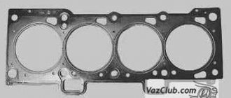
LADA at the service station: replacement of the Kalina catalyst gasket 8 valves
In view of this, owners of budget car models deliberately exclude this part from the exhaust tract.
However, the power of the power unit is reduced solely due to a violation of the throughput of the exhaust gas converter, due to damage to the honeycombs inside it. Our car service specialists identify the main reasons for premature failure of parts and wear of gaskets:
- Failure of the lambda probe, as a result of which the process of formation of the fuel mixture is disrupted.
- Incorrect operation of the ignition system;
- Low fuel quality;
- Mechanical damage to elements;
- Use of various additives;
Another difficulty lies in the fact that the catalyst is a non-repairable element, which is why in the event of a breakdown the catalyst gasket may need to be replaced. If the catalyst fails, the following symptoms are observed:
Removing the intake pipe
We remove the inlet pipeline to replace the sealing gaskets. in connecting the pipeline and the cylinder head, for removing the fuel rail, as well as when repairing the cylinder head. Disconnect the wire terminal from the negative terminal of the battery. Remove the plastic engine cover. Use a Phillips screwdriver to loosen the clamp securing the crankcase ventilation hose...
...and remove the hose from the cylinder head cover pipe.
Using a Phillips screwdriver, unscrew the self-tapping screw securing the guide tube of the oil level indicator to the intake pipe...
...and lift up the tube with the oil level indicator.
Using pliers, loosen the tightening of the band clamp securing the vacuum brake booster hose... ...and remove the hose from the intake manifold. Disconnect the end of the throttle drive cable from the drive sector (see “Replacing the throttle drive cable”). Having unscrewed the nuts securing the throttle assembly and without disconnecting the coolant hoses from it, remove the throttle assembly from the inlet pipeline (see “Removing the throttle assembly”). We disconnect the wire blocks from the ignition coils of the 1st, 2nd and 3rd cylinders (see “Checking the condition and replacing the spark plugs”)...
...and move the wiring harness to the side.
Using a 10mm socket, unscrew the two nuts of the upper fastening of the intake manifold to the cylinder head cover. Using a 13mm socket, unscrew the two bolts and three nuts of the lower fastening of the intake manifold.
Places for attaching the intake manifold to the cylinder head
(for clarity, the intake pipeline and the fuel rail with injectors have been removed): 1 - studs; 2 - holes for bolts
Unfasten or cut the two clamps securing the engine management system wiring harness to the upper timing belt cover. Disconnect the engine control system wiring harness block from the phase sensor (see “Removing the phase sensor”). We remove the ignition coils of the first, second and third cylinders (see “Checking the condition and replacing spark plugs”). We close the holes for the ignition coils in the cylinder head cover with a rag.
We move the intake pipe forward (along the direction of the car) and lift it up, bringing it out from under the wiring harness of the engine control system.
There are sealing rubber gaskets installed in the grooves of the intake manifold flange. If additional work is required after removing the intake manifold, it is necessary to cover the holes in the cylinder head with a rag to prevent objects from getting into the engine. Before installing the intake pipeline, check the condition of its sealing gaskets. If the gasket has lost elasticity or is damaged, it must be replaced with a new one. Install the intake pipe in reverse order. We tighten the bolts and nuts securing the intake manifold to the cylinder head to the prescribed torque (see “Appendices”).
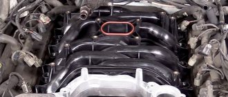
The intake manifold, or as it is popularly called the receiver, is a device that ensures a uniform flow of purified air into the cylinder head. The Priora receiver is subject to tuning and modifications, which we will talk about in this article.
In addition, the receiver accumulates air and smoothes out its vibrations, thereby ensuring smooth engine operation due to a uniform (without drops) supply of air masses. When the unit operates correctly, a highly saturated air-fuel mixture is supplied, and lower fuel consumption is achieved when the engine is running.
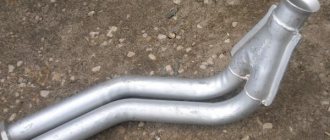
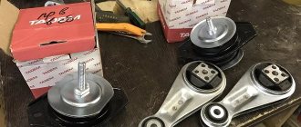
Technical features of the insert
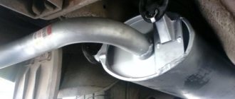
Installing catalyst replacements can eliminate the problem of a clogged exhaust filter and return the car to its previous performance - power and gas mileage. But what are these substitutes? This insert is a hollow pipe that does not have filters. It is made in the form of a catalyst and in most cases there are no problems with its installation. After installing the insert instead of the factory exhaust gas filter, drivers observe:
- acceleration of warming up of the car in the cold season;
- the car picks up speed better;
- fuel consumption is reduced.
In some cases, there is a change in the sound volume when the car is running. The sound becomes more bassy. The Lada Kalina computer can display “Check” on the dashboard when driving with the insert. To prevent this, use a lambda probe or oxygen sensor. This sensor is an integral part of the exhaust system with a catalyst. The sensor analyzes the level of oxygen and harmful gases in the exhaust and transmits the information to the on-board computer. Based on the data obtained, the computer determines the performance of the catalyst. The lambda probe cannot be repaired; if it breaks, the part must be replaced.
Since the insert does not reduce the level of toxic substances in the exhaust, the lambda probe will constantly transmit information about a catalyst malfunction. To avoid this, special devices are used - decoys. They come in two types: mechanical and electronic.
Lambda zone deception
Mechanical blende is a bronze spacer of a certain size, filled with ceramic chips coated with a catalytic layer. Exhaust gases pass through the small holes of the device, interacting with the crumbs, due to which the CO2 concentration is reduced. Electronics analyzes the changes and sends information to the computer about the normal operation of the catalyst.
Electronic snag is a high-tech device based on a single processor. Such a device analyzes the operation of the exhaust gas purification system and transmits information about the serviceability of the catalyst. The electronics understand that smog filtering is not happening, but generates a signal corresponding to the correct functioning of the system.
Installing electronic deception involves reflashing the computer to exclude from its code the calculations of dosage corrections transmitted by the rear oxygen sensor. The program does not save records of catalyst operation errors in the computer memory.
You can replace the catalyst with an insert in many car repair shops. Self-replacement is recommended only if you have the appropriate tools, skills and experience. You can install electronic deception yourself, but you need to have a good understanding of the principles of computer operation and have the necessary software. Otherwise, the car owner risks making the situation worse.
We remove the intake manifold on a 16-valve VAZ-2112 with our own hands
Sooner or later, any car enthusiast may be faced with the need to remove the intake manifold on a 16-valve VAZ-2112 engine. This may be needed to carry out incidental repair operations or other work.
The video will tell you how to remove the intake manifold, and also tell you about all the subtleties and nuances
How to replace the intake manifold on a VAZ 2170-VAZ 2172?
Removal: 1) It is attached with just some bolts and nuts, but some parts prevent you from getting to it, that’s why it doesn’t take as long to remove it as all the parts are removed that prevent its removal, first, turn off the power to the car’s on-board network since you will have to work with electronics, to do this, take a wrench and use it to remove the negative terminal from the battery, after which the on-board network will be de-energized (For more details on how to do this, if you have not yet understood, read the article: “Replacing the battery”, namely the first read the paragraph in it), as soon as the current stops supplying to all electrical equipment, remove the four ignition modules from the car engine (For clarity, all modules are indicated in the photo below with arrows, if you do not yet know how to remove them, then in this case, read the article: “Replacing spark plugs ignition on a VAZ”, be sure to read the second paragraph in this article and the note to this paragraph).
2) Let's move on, now remove the throttle assembly (it is also popularly called a throttle valve, but this is the wrong name) from the car and between this assembly, by the way, there will be the same gasket that is recommended to be replaced with a new one during any disassembly, but you should pay special attention for now do not pay attention to this gasket and read the article further, almost at the very end we will explain in detail how all these sealing gaskets are removed and in what cases they need to be replaced with new ones, and for more details on how to remove the throttle assembly, read the article: “Replacing the throttle assembly by car".
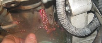
3) Then disconnect the crankcase ventilation supply hose from the pipe that is poured onto the cylinder head covers, to do this, take a screwdriver in your hands and use it to slightly loosen the hose clamp (see photo 1) and then disconnect the hose, followed by the guide with the probe which you are checking the oil level, you will need to remove it, the guide itself is attached to just one screw by unscrewing it (see photo 2) you can remove both it and the dipstick itself completely from the car (see photo 3), and then use wrenches to unscrew the two side nuts that secure the intake manifold to the cylinder head (see photo 4).
4) After unscrewing the side nuts, using a wrench or a socket wrench (Depending on what you have), unscrew the three central nuts and the two outermost nuts (see photo 1) and immediately after that remove the manifold from the car engine .
Installation: A new intake system manifold on a car is installed in the reverse order of its removal, but only you should know some aspects of its installation, firstly, it is possible that you did not remove it for replacement, but in order to get to other parts, for example, so on the removed the manifold has sealing gaskets, we mentioned them a little earlier, they can be removed quite easily, but if you don’t have new ones, then we don’t recommend disturbing the old ones, otherwise you’ll tear them, it’s recommended to always replace these gaskets with new ones, but if that’s not possible, then don’t remove them just visually inspect them, if cracks or traces of defects are found on them, then replace these gaskets with new ones (Where are all five gaskets located and how to remove them, see photos 1, 2 and 3), in addition, when installing the manifold back, take a lot of newspapers and crumple them up and put them in all four holes, which are indicated by arrows in photo 4 (But just make sure that they don’t fall inside), then take a brush that won’t scratch the metal too much and use it to clean the edges of the seats of those same sealing gaskets , it’s just that over time, pieces of gaskets stick to these edges, which is unacceptable, and therefore the edges must be clean and free of roughness that a brush with a metal part can cause, so do not use brushes with a metal rag.
Note! By the way, if these gaskets are deformed, the connection of the intake system is broken and the car, in the literal sense of the word, will start to shake and run poorly (This is all because of the small sealing gaskets, which is why we advise replacing them immediately with new ones), you will most likely It takes a long time to look for the problem, but it turns out to be very simple, the intake manifold gaskets were not changed in time, so keep this in mind!
Additional video clip: Just below, as you can see, there are two video clips, they don’t particularly show how to replace the manifold on cars, but they are interesting because the person explains and shows in practice which intake manifold adds the most power to a 16 valve car , look at them carefully and perhaps instead of the original collector you will install a sports one on your car and there are no particular disadvantages from them, and even more so, as some say, the resource does not decrease from them.
Note! Let’s add to the word (About the resource), a very large number of people have recently installed zero resistance filters on their cars, they say the car drives better on them, so if you are thinking about this filter, then we are immediately recalling you, because all the dust that is in the air is not properly cleaned by this filter and thereby flies into the car engine (For the mirror part of the cylinders, dust is like sandpaper, it scratches the mirror part and soon scratches will appear on it, which will slightly increase the coefficient of friction of the pistons in the cylinders and thereby the power of the car decrease and the resource will also decrease accordingly, since the mirror part of the cylinders will suffer from this), and the collector only has different shapes and with these shapes correctly selected, the car can drive noticeably better, so think about installing it on your car and that same video (This is a continuation of the first by the way) see below:
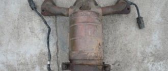
Replacing the exhaust manifold and gasket
When dismantling the manifold, the gasket is destroyed in almost any case. Therefore, it is worth removing its remains from the parts. Replacing the Kalina exhaust manifold gasket is a simple process. The use of sealants and other third-party substances is not recommended. They may later get into the crankcase.
Replacing the manifold itself is simple - just take a new part and install it according to the principle in which it was attached. Assembling the system is simply the reverse order of the steps outlined in the last section.
Advice! Don't forget about cleanliness. This is an important factor in long and trouble-free operation of the car.
What is a cylinder head?
The cylinder head is one of the main components of the engine. It consists of a cover that serves to protect internal parts from external environmental influences. The cylinder head is made by spot casting from cast iron or aluminum alloy. To remove residual stress that occurs during the casting stage, the product is artificially aged using mechanical processing.
The lower part of the cylinder head is more expanded, thus it more reliably protects the insides of the block. The inside of the head is perfectly smooth. The unit consists of a large number of elements.
Structure of the Lada Priora cylinder head
In the upper part of the cylinder head there is space for camshaft bearing housings, valve springs, bushings and support washers, as well as for the gas distribution mechanism. Since the head consists of a large number of parts, the process of assembling and disassembling the cylinder head is very labor-intensive. Together, the parts of the unit convert the energy from fuel combustion into mechanical energy, which allows the vehicle to move.
Priora 90 repair
Removing the cylinder head
We carry out work when replacing the cylinder head gasket, repairing and replacing the cylinder head, as well as when dismantling the connecting rod and piston group of the engine. Relieve the pressure in the power system (see “Replacing the fuel filter”). Disconnect the wire terminal from the negative terminal of the battery. Remove the air filter (see “Removing the air filter”). Disconnect the wire tip from the low oil pressure indicator sensor (see “Removing the low oil pressure indicator sensor”). Disconnect the injector wiring harness block from the engine management system wiring harness block (see “Removing the fuel rail and injectors”). Drain the coolant from the engine cooling system (see “Replacing the coolant”). Remove the rear support of the power unit (see “Removing the supports of the power unit”). Remove the cylinder head cover (see “Removing camshafts and replacing valve lifters”).
Using a 10mm socket, unscrew the bolt securing the ground wire end of the engine management system wiring harness.
Using the “13” socket, unscrew the nut securing the tip of the wire coming from the “negative” terminal of the battery... ... and remove the tip of the wire from the cylinder head stud. To make it easier to unscrew the nuts securing the thermostat housing, disconnect the wiring harness blocks from the coolant temperature gauge sensor (see “Removing the coolant temperature gauge sensor”) and the coolant temperature sensor (see “Removing the coolant temperature gauge”).
Using a 13mm socket, unscrew the two nuts securing the thermostat housing to the cylinder head.
Without disconnecting the cooling system hoses from the housing pipes and the thermostat cover, remove the housing assembly with the thermostat cover from the cylinder head studs. The connection between the flanges of the thermostat housing and the cylinder head is sealed with a gasket. If the gasket is torn or delaminated, then during subsequent assembly it must be replaced with a new one. Remove the camshaft gear pulleys (see “Replacing camshaft seals”).
We remove the guide tube of the oil level indicator from the cylinder block pipe.
Using a “17” wrench, unscrew the fitting of the fuel supply tube to the ramp, holding the tip of the fuel hose with a wrench of the same size.
Remove the hose from the tip of the tube. A rubber ring is installed at the tip of the tube. If the ring is damaged, replace it with a new one during assembly. Loosen the nuts securing the coolant pump supply pipe bracket and remove the bracket from the cylinder head stud (see “Removing the catalytic collector”). Remove the rear timing belt cover (see “Removing the coolant pump”). The cylinder head can be dismantled assembled with or without the catalytic collector by unscrewing the nuts securing the catalytic collector and removing it from the cylinder head studs. During operation, due to the high temperature in the area of the catenary collector, the nuts securing it to the cylinder head studs may “stick”, and it may be difficult to unscrew them in the engine compartment. Therefore, we show a method for removing the cylinder head assembled with the catalytic collector. We disconnect the pipe of the additional muffler from the catenary collector (see “Replacing the gasket in the connection between the catalytic collector and the additional muffler”). We unscrew the two bolts securing the catenary collector to the cylinder block bracket (see “Removing the catenary collector”). We disconnect the wiring harness blocks of the control and diagnostic oxygen concentration sensors from the wiring harness blocks of the engine control system (see “Removing oxygen concentration sensors”). Using a 10mm hexagon, unscrew the ten screws securing the head to the cylinder block.
Location of the cylinder head mounting screws Remove the head mounting screws with washers.
With an assistant, remove the cylinder head.
Remove the cylinder head gasket (A - centering sleeves).
The cylinder head gasket must not be reused. The gasket must be replaced with a new one. Before installing the cylinder head, remove carbon deposits from the surfaces of the combustion chambers and clean the mating surfaces of the head and cylinder block from dirt and oil. We remove oil and coolant from the threaded holes (for the head mounting screws) of the cylinder block. We install the cylinder head in the reverse order. We install the new cylinder head gasket and the head itself along two centering bushings. Before screwing in the cylinder head mounting screws, dip the screws in engine oil and let it drain.
Procedure for tightening the cylinder head screws
We install the cylinder head mounting screws, tighten them and tighten them in three steps according to the scheme: – first step – tighten the screws to a torque of 20–25 Nm (2.0–2.5 kgf m); – the second step is to turn the screws by 90°; – the third step is to turn the screws by 90°. The cylinder head screws can only be reinstalled if they have been stretched to a length of no more than 95 mm (excluding the height of the screw head). If the length is longer, replace the screws with new ones.
The sequence of work is as follows
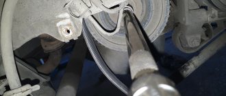
First, the pipe of the additional muffler, which is connected to the catalytic collector, is disconnected. To do this, you need to bend the edges of the plate and unscrew the fastening nuts. Is this where you need a key for 13? with additional extension cord. After this, the locking plate is removed. Once the locking plate is removed, the heat shield is removed. The flange of the muffler pipe is moved, after which the sealing gasket is removed from the studs of the catalyst manifold. After this, the blocks with contact wires are disconnected from the oxygen concentration control and diagnostic sensors installed on the catenary collector. To remove the exhaust manifold, you need to unscrew the two bolts that secure the exhaust manifold to the car engine cylinder block. For these purposes, a 13? key head is used. After the bolts are unscrewed, the catcollector bracket is removed.
By the way, if the starter fails, we recommend looking for it on the website https://www.startvolt.com/catalogue/startery/gaz/.
To remove the collector, you need to unscrew the nut on the rear engine mount and loosen the bolt securing the engine mount to the car body. After this, you need to remove the bolt on the engine mount. Unscrew the three nuts securing the support bracket to the cylinder head. After loosening the nuts, the bracket moves along the cylinder head studs.
The fastening nut on the supply pipe of the coolant supply pump is unscrewed. After loosening the fastening of the bracket to the pump pipe stud, the bracket is moved away from the cylinder head. The eight nuts securing the exhaust manifold are removed. For this purpose, a 13? head is used. The exhaust manifold of the Lada Priora car moves along the cylinder head studs and is pulled down.
08/15/2015Found a mistake? Select the text with the mouse and press Ctrl+Enter Was this information useful? Sources used:
- https://ladaservice.info/lada-priora/dvigatel/snyatie-i-ustanovka-resivera-na-priore/
- https://xn—-8sbabr6ahc3e.xn--p1ai/priora-remont/587-zamena-vypusknogo-kollektora-priora.html
- https://vsepoedem.com/story/snyatie-vypusknogo-kollektora-na-priore
Repairing engine 21126 VAZ 2170 Priora after timing belt break
Today we brought one of the old clients to the Priora, as it turned out, the jammed pump broke the belt and, as a result, the valves were bent.
But progress at AvtoVAZ does not stand still, and if on the engines of the tenth family the valves were simply bent, then on the Priora 126s the connecting rods also lose alignment and, if they are not changed, there is a high probability that the engine will begin to eat oil and, accordingly, your money. Glory to the designers of AvtoVAZ!
But every cloud has a silver lining, there are sets of pistons for 126 engines with grooves that do not bend the valves. In this article we will describe the procedure for repairing the cylinder head after a broken timing belt, as well as replacing the piston. Removing and installing the timing belt is described in this article, so we will not dwell on it in detail.
To perform this procedure, torque wrenches are required!
I use two keys: 28-210 Nm with a 1/2 square and 5-25 Nm with a 1/4 square.
- Let's start to disassemble
- Cylinder head repair
- Video of manually grinding valves
- Let's move on to the cylinder block
- Eliminating longitudinal play of the crankshaft
- Assembling the piston
- Checking the thermal gap in the piston rings
- Installing new rings
- Engine assembly
Let's start to disassemble
First, drain the oil and antifreeze. We remove the protective cover, the air filter with pipes, disconnect the ignition coil connectors, the throttle cable and the throttle assembly.
We remove the thermostat housing and simultaneously disconnect all the available connectors and pipes. We remove all the wiring that was in our way towards the battery.
We remove the generator. We unscrew the eight thirteen nuts holding the intake manifold and remove it. We unscrew all the bolts securing the valve cover, as well as the side engine support.
Unscrew the eight nuts and remove the exhaust manifold.
Remove the timing belt, camshaft pulleys and pump.
In three passes, so as not to deform the part, we first loosen and then unscrew twenty bolts of the camshaft bearing housing, the head is eight. Be sure to follow the sequence shown in the photo.
Remove the bearing housing. We remove the camshafts; there is a distinctive lip on the intake camshaft.
Also, in several passes, we first loosen and then unscrew the ten cylinder head mounting bolts. Be sure to follow the sequence shown in the photo.
Remove the cylinder head. All sixteen valves are replaced.
Required tools and materials
The list of what is needed is, in principle, standard: a standard set of tools, an extension cord with various heads, WD-40 or other similar lubricant. If you know that the problem is broken studs, then a stud extractor, taps, drill and drill bits will be added to the above list. In addition, a bucket or basin, possibly an old canister, should be at hand.
Advice! A few days before replacing the exhaust manifold, you can begin to lubricate all fasteners in the system. Can be lubricated several times a day. This will greatly simplify the task and make replacement quick.