Injector wiring diagram
Today, in practice, many motorists replace the carburetor with an injector, since the latter has a number of advantages. At the same time, installing an injector contains a number of nuances. In this situation on the VAZ 2110, the injector circuit plays a certain role as a guide that will help you understand all the nuances that will be encountered during installation. Plus, the electrical diagram of a VAZ 2110 injector with 8 valves or 16 is necessary for a practical understanding of the functioning of this device, and if there is none, then all repair work will simply be ineffective.
Injection engine VAZ 2110
The injection system is represented by two components:
- fuel distributor;
- ignition control system.
Wiring diagram VAZ 2110 16 valves injector
The systems presented above are controlled by an electronic unit that coordinates the operation of the two systems, and thereby increases the overall degree of efficient functioning of the injection system.
VAZ-2110 fuel system: design, possible breakdowns, repairs
In our short article we will talk about the VAZ-2110 fuel system (injector). Carburetor engines have long gone into oblivion. The manufacturer has not installed such motors since the early 2000s. Most of the “ten” and similar models (2112, 2111) are equipped with engines with a fuel injection system. It is more reliable, works stably, and most importantly, does not require frequent intervention from the driver. The engine will be able to operate without problems, but provided, of course, that all filters are changed in a timely manner. There is also a requirement for fuel - it is not recommended to use low-quality fuel.
Which is better: carburetor or injector?
And now a little about which VAZ-2110 engine will be more reliable: an injector or a carburetor? But you need to look at this issue from different angles. For example, beginners will like the injector. Constant speed, there is no need to shut off the air supply in cold weather, and starting off is much easier. But there is another advantage - the car is more responsive at high speeds. Even at a speed of 120 km/h, when you press the gas pedal, the car quickly picks up speed. With carburetor engines this happens much more slowly. Therefore, overtaking in a car with an injector is safer. But when starting from a traffic light, the carburetor will easily “break” the injector. And the reason is higher torque at the bottom. And the cost of maintenance, of course, is higher for injection “tens”, since sometimes it is not easy to make an accurate diagnosis in the event of a breakdown.
Basic moments
The fuel system of the VAZ-2110 (8 valves or 16) includes a fairly large number of elements that affect the operation of the engine. It is also worth mentioning that a mixture of gasoline and air is supplied to the combustion chambers of any engine in a certain proportion (more precisely, 14 parts of air and 1 gasoline).
If this ratio is violated, the engine will start to work incorrectly - the speed will decrease or increase, and interruptions will appear.
Do-it-yourself replacement of the VAZ 2112 fuel pump mesh
Why do you need to replace the VAZ 2112 fuel pump mesh?
Installing a mesh in the fuel pump VAZ 2112
The heart of the car is the engine. It cannot work without the correct supply of gasoline to it, like the movement of blood through the human body. The main fuel supply unit in a VAZ 2112 car is a gasoline pump, which pumps gasoline through its supply system to the filter, and then into the combustion chamber. Its period of operation depends on how pure gasoline flows into the gas pump. There are situations when the car moves jerkily or even stops. In such a situation, you need to start repairs from the easiest way - the VAZ 2112 fuel pump mesh must be replaced. The mesh can become clogged to such an extent that it surprises even experienced auto mechanics. The main reason for this is the poor quality of gasoline.
When is it necessary to replace the mesh on the fuel pump?
The condition of the unit can be judged by its performance and the pressure developed. To do this, you need to connect a pressure gauge to the fuel system through a special adapter. This diagnosis is done at a service station. It’s easier to diagnose a fuel pump at home like this:
- The ignition is turned on, but the VAZ fuel pump does not work, there is no characteristic hum or makes a loud noise, which entails an overload of the unit and shortens its service life.
- The pump performance decreases, which is clearly visible when driving at third and fourth speeds on a flat road. The car does not respond when the driver presses the gas pedal.
- If a VAZ 2112 car “spontaneously” slows down while driving. This most likely indicates that there is a problem with the fuel supply to the gas tank.
- The reasons may be: clogged coarse or fine filters. The fine filter must be replaced, and the coarse filter (mesh) can be washed. But this will only give a temporary effect; after a short period of time, you will still need to replace the fuel pump grid on the VAZ 2112. Any car owner can purchase it at a car store without any problems. The price of the part is small, the DIY process will take a little time, but the reliability of the gas pump will increase for a long time.
Design Features
The fuel system design includes the following components:
- The fuel supply system itself consists of a gas tank, a pump, a pressure regulator, gasoline filters, a ramp and injectors, as well as connecting tubes and hoses. In other words, these are the elements in which gasoline is found.
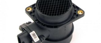
- The air supply system is those elements that allow oxygen to pass through. This is an air purification filter, a pipe, a throttle assembly, and a flow sensor. It is with the help of these elements that purified air is supplied to the fuel rail to form a mixture.
- And the last system allows you to catch gasoline vapors. This is an adsorber and connecting tubes. With their help, couples are destroyed.
The fuel supply system is needed to ensure the presence of the required amount of mixture in the ramp when operating in any mode.
Differences in power systems
It is worth noting that the power supply systems for the VAZ-2111 and VAZ-2112 engines are slightly different from the VAZ-21114 and VAZ-21124. The last two do not have a return line through which gasoline returns to the tank. The reason is that the fuel pressure regulator is located in the same module as the fuel pump, in the tank. Therefore, it is possible to control the pressure in the system at an early stage, so to speak. And in this case, there is no need to lay a return line.
In addition, in order to connect various components of the line, the VAZ-21114 and VAZ-21124 engines use clamp-type tips, rather than threaded fittings. There are also differences in the shape and design of the ramp; newer injectors are installed on it. And most importantly, the pressure in the system is slightly higher than on earlier engine models.
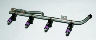
Ramps and injectors
The ramp is a hollow bar with nozzles installed on it and a specially designed mixture pressure regulator. The ramp is mounted with two bolts on the intake pipe or directly on the cylinder head. On the left side there is a fitting with which the fuel pressure is monitored (during diagnostics). It is closed with a threaded plug.
The injectors are fixed to the ramp. The injector nozzles are located in the intake manifold openings. But on the VAZ-2112 and VAZ-21124 engine models, the injectors are installed in the holes on the cylinder head. In order to seal the mounting holes of the electromagnetic injectors, rubber rings are installed. An injector is a regular valve with an electromagnet.
When a pulse is received from the microcontroller, the valve opens for a certain time. In this case, the fuel mixture is supplied through a sprayer into the combustion chamber through a valve. The fuel begins to evaporate, comes into contact with hot elements, and in a state of steam ignites in the combustion chamber. Ignition occurs with the help of a spark plug. As soon as the pulse to the injector stops, the valve returns to its original position using a return spring.
Air intake and throttle valve
The first thing we will consider from the design of the VAZ-2110 fuel system (injector, 8 valves) is the air supply. An air purification filter is installed at the inlet - on the “tens” it is made of paper, flat, and has a large surface area. Due to this, filtration occurs as efficiently as possible. The design of the throttle assembly looks like this:
- The pipe through which liquid from the cooling system is supplied to the housing.
- The pipe through which the crankcase is ventilated during idle operation.
- A pipe through which liquid is drained.
- A sensor that allows you to determine the position of the damper when the engine is running.
- Idle air control (you can’t call it a sensor, since the device doesn’t measure anything). This is a simple stepper electric motor that allows you to change the amount of air supplied to the ramp when idling.
- Fitting – necessary for purging the adsorber.
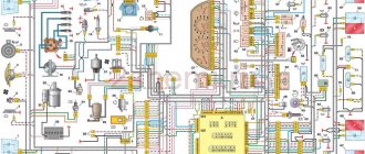
Electrical circuit of ECM VAZ-21101
1 — VAZ-21101 controller; 2 — block of the ignition system harness to the ABS cabin group harness; 3 — diagnostic block; 4 — immobilizer warning sensor; 5 — immobilizer control unit; 6 — ignition coil; 7 — spark plugs; 8 — nozzles; 9 — electric fuel pump; 10 — block of the ignition system harness to the fuel level sensor harness; 11 — block of the fuel level sensor harness to the ignition system harness; 12 — block of the ignition system harness to the injector harness; 13 — injector harness block to the ignition system harness; 14 — speed sensor; 15 — idle speed regulator; 16 — throttle position sensor; 17 — coolant temperature sensor; 18 — mass air flow sensor; 19 — oil pressure warning lamp sensor; 20 - phase sensor; 21 — oxygen sensor; 22 — crankshaft position sensor; 23 — knock sensor; 24 — solenoid valve for purge of the adsorber; 26 — coolant temperature indicator sensor; 27 — block of the ignition system harness to the instrument panel harness; 28 — block of the instrument panel harness to the ignition system harness; 29 — controller power supply fuse; 30 - ignition relay; 31 - ignition relay fuse; 32 — fuse for the electric fuel pump power supply circuit; 33 — electric fuel pump relay; 34 — electric fan relay; 35 — ignition system harness block to the air conditioner connector; 36 — block of the ignition system harness to the side door harness. 37 — electric fan of the cooling system; 38 — diagnostic connector; 39 — ignition switch; 40 — instrument cluster; 41 — on-board control system unit; 42 — starter relay; 43 — contacts of the 8-terminal blocks of the instrument panel harness and the front harness; 44 — contacts of the 21-terminal blocks of the instrument panel harness and the rear harness; 45 - trip computer.
- A - to the “plus” terminal of the battery;
- B1 — grounding point of the fuel level sensor harness;
- B2, B3 — grounding points of the ignition system harness;
- C - to the starter;
- D - to the driver's door interior lamp switch.
Throttle design features
The throttle assembly is attached directly to the receiver. With its help, air is dosed, which enters the intake pipe. A throttle assembly is installed between the inlet pipe (with filter) and the ramp. The damper is connected to the gas pedal via a cable. A sensor is installed on the damper itself; it allows the electronic control unit to determine the position of the damper when the engine is running.
It is worth noting that the fuel system of the VAZ-2110 (16 valves) is approximately the same in design as that of an eight-valve engine. In the flow part of the throttle assembly (immediately before the valve and immediately after it) there are holes that allow vacuum to be removed. With their help, the system responsible for ventilation of the adsorber and crankcase operates. If an adsorber is not installed on the car, the fitting required for purging is closed with a rubber plug. On VAZ-21114 and VAZ-211124 engines there is no channel through which air is supplied to bypass the damper. The connecting flange also has a slightly different shape.
Diagnostics of injection engines - how to come to the aid of your car?
Primary diagnostics of injection engines consists of monitoring the condition of all control sensors of the unit. To do this, a thorough inspection is carried out, during which it is necessary to ensure the integrity of the insulation and the reliability of the connection of the plug connectors.
Diagnostics and repair of injection engines - briefly about the device itself
But first, let's look at what an injection engine is. How is it different from a carburetor? The main difference is the air-fuel mixture supply system. In previous engines, the fuel mixture was sucked directly through the carburetor, where the components were dosed, and then the gasoline was mixed with air. At the same time, due to imperfect design, the engine lost up to 10% of power.
In a fuel injection (or injection) engine, fuel enters the combustion chamber by forced injection at high pressure through injectors. Dosing and control of the amount of incoming fuel is carried out by electronics. As a result, the level of harmful emissions into the environment is reduced, and engine power is significantly increased, its performance characteristics are improved, and fuel consumption is reduced.
Advantages of injection systems:
- precise dosage of fuel supply;
- by optimizing the composition of the air-fuel mixture, the level of toxicity of exhaust gases becomes significantly lower;
- the dynamic characteristics of the car are improved, the injection system adjusts the fuel supply depending on the load;
- the use of an injection system leads to an increase in engine power by more than 7%.
Disadvantages include expensive repairs to the injection engine power supply system, fairly high requirements for fuel quality, and the availability of special equipment for repairs and diagnostics.
Diagnostics of injection engines - how to detect a breakdown yourself?
What malfunctions most often plague injection systems? The most significant malfunction can be considered a breakdown of the sensor that controls the position of the crankshaft. In this case, engine repair is most often required, since the alarm failure is caused by serious problems with the power unit.
Preliminary diagnostics of an injection engine with your own hands is quite possible, but to accurately determine the cause of the malfunction you will need special equipment, which is only available at service stations. If the fuel pump fails along the way, the only thing that can be done is to replace the faulty unit. If it is not in stock, then you will have to rely only on a tow truck.
The simplest failure is considered to be the failure of the phase sensor. The injection system is designed in such a way that in the event of such a malfunction, it begins to supply twice as much fuel. It is unlikely that you will be able to determine the cause of excessive fuel consumption on your own; this will require special instruments for diagnosing injection engines.
Do-it-yourself injection engine diagnostics - a few more observations
What else can lead to a sudden increase in engine power consumption? Experts recommend paying attention to the mass air flow sensor. This malfunction can be identified by dark exhaust, decreased throttle response, the appearance of unpleasant jerks and unstable engine operation in idle mode. Naturally, you can drive such a car, but only to the nearest service station, where injection engines are diagnosed and repaired.
It happens that the engine starts to stall. Experienced drivers know that the reason may not only be a malfunction in the fuel supply, but most often this occurs due to breakdowns of electrical equipment (faulty ignition coil, spark plugs, etc.). Even a novice car enthusiast can determine this. But if you need to repair injection engines, the malfunctions of which have already been described in this article, then it is best to contact professional service centers.
An injection engine is a rather complex mechanism, the operation of which must be well tuned in order to get maximum performance from it. The article discusses in detail the operating principle of an injection engine.
Before we start talking about this miracle of technology, let's dispel some myths. An injection engine works on the same principle as a diesel engine, with the exception of the ignition system, however, this does not give it much more power than a carburetor engine. The increase will be a maximum of 10%.
The center of the entire system is the ECU (electronic control unit). It goes by many names, "brains", "computer" and so on. Essentially, yes, it’s a computer that contains a huge number of tables on mixture composition, fuel injection time, and so on. For example, if the engine speed is 1500, the throttle is open 10 degrees, and the air flow is 23 kg, then one amount of fuel will enter the cylinder. If the input parameters change, then the result will be different. If any problems arise with the control unit, for example, the firmware crashes, then everything goes to waste, the engine either starts to work haphazardly or stops altogether.
Idle speed adjustment
On carburetor engines, cold starting was quite difficult - it was necessary to pull the “choke” cable so that more gasoline and less air entered the combustion chambers. And it was necessary to open the air supply in a timely manner, otherwise the car would “eat” gasoline very greedily. As for adjusting the idle speed on injection engines, a specially designed engine (IAC) is used for this.
When the valve is closed, air enters the fuel rail through a thin channel, bypassing it. This channel is closed by a conical needle, which is mounted on the regulator. The microcontroller control system, depending on the engine operating mode, sends a signal to the electric motor. At the same time, the needle moves, changing the air supply to the ramp. At the same time, a certain engine speed is maintained - specifically, 750 rpm.
Knock sensor VAZ 2111
15 customers chose this product
- Description
- Shipping and payment
- Reviews (0)
The old-style knock sensor is intended to replace a failed standard one.
Set: 1 sensor
Product delivery options
Note! Below are the shipping methods available specifically for this product. Payment options may vary depending on the shipping method. Detailed information can be found on the “Delivery and Payment” page.
Parcel by Russian Post
Available payment methods:
- Cash on delivery (payment upon receipt)
- Using cards Sberbank, VTB, Post Bank, Tinkoff
- Yandex money
- QIWI
- ROBOKASSA
Shipping throughout Russia. Delivery time is from 5 to 12 days.
Parcel by Russian Post 1st class
Available payment methods:
- Cash on delivery (payment upon receipt)
- Using cards Sberbank, VTB, Post Bank, Tinkoff
- Yandex money
- QIWI
- ROBOKASSA
Shipping throughout Russia. Delivery time is from 2 to 5 days. More expensive than regular delivery by Russian Post, approximately 50%. Parcel weight up to 2.5 kg
Express Parcel EMS
Available payment methods:
- Cash on delivery (payment upon receipt)
- Using cards Sberbank, VTB, Post Bank, Tinkoff
- Yandex money
- QIWI
- ROBOKASSA
Shipping throughout Russia. Delivery time is from 3 to 7 days. More expensive than regular delivery by Russian Post, approximately 100%.
Transport companies
Available payment methods:
- Using cards Sberbank, VTB, Post Bank, Tinkoff
- Yandex money
- QIWI
- ROBOKASSA
Delivery is possible to any locality where there is a representative office of the transport company. Delivery time is from 2 to 10 days. Sending large parcels is approximately 50% more profitable than by Russian Post.
Gasoline pump and purification
Using a two-stage electric drive, the fuel pump pumps gasoline into the line. The pump is of a rotary type, it is not dismountable, and is installed directly in the gas tank. This reduces the possibility of a vapor lock occurring, since gasoline is injected under high pressure and not under vacuum. The pressure value is about 284 kPa on VAZ-2111 and VAZ-2112 engines, and also over 364 kPa on VAZ-21114 and VAZ-21124 engine models.
The gasoline filter is built into the supply line directly between the ramp and the electric pump. It is located under the body, directly next to the fuel tank. The filter is a non-separable element; the housing is made of steel. Inside there is a paper type filter element. For rough cleaning of fuel, a so-called diaper is used, which is installed in the lower part of the pump.
Fuel pressure adjustment
How is pressure maintained in the fuel system of the VAZ-2110? On cars with VAZ-2111 and VAZ-2112 engines, a pressure regulator is installed directly on the fuel rail. With its help, a certain pressure value is maintained inside. Moreover, it allows you to maintain both air pressure in the intake pipe and fuel inside the ramp.
The design of the regulator is not very complicated. Inside it are a valve, a diaphragm and a return spring. When the engine is running, the regulator allows you to maintain pressure in the range of 284-325 kPa. On the one hand, the diaphragm of the device is affected by fuel, and on the other, by low pressure in the intake pipe. As soon as the pressure in the intake manifold decreases, the valve begins to open. In this case, excess fuel is passed into the drain line to the tank. The pressure in the ramp is significantly reduced.
As soon as the pressure in the intake manifold increases (this happens when the damper opens), the valve on the regulator begins to open at a significantly higher pressure of the fuel mixture. At the same time, the fuel pressure inside the ramp increases significantly.
But on VAZ-2114 and VAZ-21124 engines, the pressure regulator is placed inside the module, next to the fuel pump. This is a kind of check valve in the fuel system of the VAZ-2110, which operates at a certain pressure (about 400 kPa). If the pressure exceeds the norm, the drain line opens and excess fuel is returned back to the tank.
Source
The fuel system of a car is a unit that supplies the fuel-air mixture to the combustion chambers of the engine. A lot depends on this unit, because all the electronics and mechanics of the car use the energy of burned fuel. The system has many parts, each of which is responsible for its own area, so stable and trouble-free operation is directly related to the serviceability of the following elements:
- fuel tank
- submersible pump (or diaphragm in carburetor engines)
- fuel level sensor and instantaneous fuel consumption sensor
- fuel channels and filters
- intake manifold
- air damper and idle air control
- ramp and injectors
- carburetor (VAZ-21100 engine)
Purpose and place of fuel hoses in VAZ cars
The fuel system of any car consists of a relatively small number of components - a tank, filters, a pump, a carburetor (in classic carburetor engines) or a fuel rail with injectors (in injection engines), etc. All these components are connected by a network of pipelines through which fuel circulates. In this case, pipelines consist of two parts - metal tubes and rubber hoses.
The combined design of pipelines is used for a reason. The fact is that individual parts of the car and components of the fuel system, although they are fixed in strictly defined places, still do not have an absolutely rigid fixation. While the car is moving, parts, especially those located on the engine (carburetor or ramp with injectors), move relative to each other, so they cannot be rigidly connected with metal tubes. Elastic rubber hoses come to the rescue, ensuring uninterrupted fuel supply regardless of the position of the fuel system components.
If we talk about fuel hoses in general, they perform several main functions:
- Communication of vehicle fuel system components;
- Compensation for longitudinal and transverse displacements of fuel system components during vehicle operation;
- Compensates for movement of fuel system components when performing various adjustments, maintenance or repairs.
Thus, they play an important role in the operation of the vehicle. This fully applies to all cars of the Volzhsky Automobile Plant, the hoses of which will be discussed in more detail.
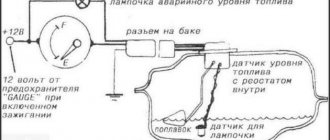
Fuel system on VAZ-2110 injector
The VAZ 2110 injector fuel system diagram is fundamentally different from the carburetor version described above. The fuel pump is located in the gas tank and pumps gasoline through the fuel filter directly into the rail. The ramp has a mechanical valve (fuel pressure regulator) that maintains a certain pressure. Next, the injectors are switched on, opening at the command of the engine control unit for a certain time, which depends on a number of factors.
Air is supplied through the air filter and throttle assembly. The throttle assembly consists of a throttle valve controlled by the gas pedal, as well as an idle speed regulator. The air is supplied directly to the intake manifold and mixed with the fuel sprayed by the injector.
The above-described power system is used on most VAZ engines. The fuel system of the VAZ 2110 8-valve injector is practically no different from the power supply circuit of a 16-valve engine.
principle of operation, device, how it differs from a carburetor
Every car enthusiast knows that a car can have either an injection engine or a carburetor. But not everyone knows what each of them is. Therefore, you should understand this issue as best as possible. First, let's note that the function is the same. A combustible mixture is formed and supplied to the engine. There is only a big difference between their work. Let's consider which one.
The principle of operation of an injection type engine
To be specific, a carburetor is a device that creates a mixture of air and fuel, and it is also able to regulate the flow of the resulting mixture. The principle of operation is to suck it into the motor. This is possible due to the fact that the intake manifold and the atmosphere have different pressures.
An injection engine involves the operation of electronics. In this system, the quality of the mixture is controlled without human intervention. It is injected in doses using nozzles. After injection, the mixture is sent to the engine for combustion. Currently, cars are equipped with an electronic rather than a mechanical system. Next, let's look at how one differs from the other.
Comparison of injector and carburetor
Let's look at the principle of operation of a carburetor. This device is capable of forming a mixture that consists of air and fuel. The mixture is rich in flammable and flammable substances. It is needed so that the motor can carry out the required work. No matter how many revolutions the propulsion system makes, it absorbs the same amount of mixture by volume.
In terms of costs, the carburetor consumes a lot of fuel. At the same time, the air becomes heavily polluted.
Now let's look at the operating principle of the injector system. The whole device works in such a way that a lean mixture of air and fuel is sent to the engine, which must be accurately dosed. In modern cars this occurs under the influence of the control unit. Since fuel is dosed in grams (portions), its consumption is significantly low. In addition, the toxicity of exhaust gases is practically zero when leaving the exhaust pipe. It turns out that the internal combustion engine practically does not pollute the air.
The injector can increase engine power by up to ten percent, and the valve block is designed in such a way that engine performance improves. The principle of operation that allows the internal combustion device is that the injector forms a mixture of air and fuel, and what is important for it is fuel that is of different quality, otherwise it is impossible to drive the car.
Also, I would also like to note that, unlike a carburetor, which freezes in winter and overheats in summer, the injector is not affected by the temperature of the external environment.
If we talk about how reliable a carburetor is, its operating principle is very simple. The device is made in such a way that after fuel combustion, heavily polluted air comes out through the exhaust pipe. But it does not require regular maintenance and repair work during operation. It is only important, in order not to damage the device, to use a fuel filter and only a high-quality brand.
Signs of malfunction of the VAZ-2110 power system
Considering the number of power system components, it is quite difficult to unambiguously determine the cause of the malfunction. But, if you know the main “symptoms” of a breakdown, then the process of finding the cause will speed up many times. So, we list the main signs of failure of power system components:
- The car stalls (does not start). Check the operation of the fuel pump by listening to the sound from under the rear seat (with the ignition on).
- The revolutions “float”. This may be due to a malfunction of the idle air control or fuel pressure regulator in the rail.
- The engine "troits". As a rule, the cause is faulty injectors.
The fuel system of the VAZ 2110 16-valve injector has exactly the same features as the 8-valve injector.
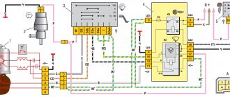
Electrical circuit of ECM VAZ-21104
1 — block of the ignition coil wiring harness to the ignition system harness; 2 — block of the ignition system harness to the ignition coil wiring harness; 3 — ignition coils VAZ-21104; 4 — immobilizer warning sensor; 5 — immobilizer control unit; 6 — spark plugs; 7 — nozzles; 8 — diagnostic block; 9 — block of the ignition system harness to the ABS cabin group harness; 10 - controller; 11 — electric fuel pump; 12 — block of the ignition system harness to the fuel level sensor harness; 13 — block of the fuel level sensor harness to the ignition system harness; 14 — block of the ignition system harness to the injector harness; 15 — injector harness block to the ignition system harness; 16 — block of the ignition system harness to the side door harness; 17 — speed sensor; 18 — idle speed regulator; 19 — throttle position sensor; 20 — coolant temperature sensor; 21 — mass air flow sensor; 22 — oil pressure warning lamp sensor; 23 - phase sensor; 24 — oxygen sensor; 25 — crankshaft position sensor; 26 — knock sensor; 27 — solenoid valve for purge of the adsorber; 28 — oil level sensor; 29 — coolant temperature indicator sensor; 30 — block of the ignition system harness to the instrument panel harness; 31 — block of the instrument panel harness to the ignition system harness; 32 — ignition relay; 33 - ignition relay fuse; 34 — fuse for the electric fuel pump power supply circuit; 35 — electric fuel pump relay; 36 — electric fan relay; 37 — controller power supply fuse; 38 — ignition system harness block to the air conditioner connector; 39 — instrument cluster; 40 — ignition switch; 41 — electric fan of the cooling system; 42 — on-board control system unit; 43 — starter relay; 44 — contacts of the 8-terminal blocks of the instrument panel harness and the front harness; 45 — contacts of the 21-terminal blocks of the instrument panel harness and the rear harness; 46 — trip computer; 47 - diagnostic connector.
- A - to the “plus” terminal of the battery;
- B1 — grounding point of the ignition coil wiring harness;
- B2 — grounding point of the fuel level sensor harness;
- B3, B4 - grounding points of the ignition system harness;
- C - to the starter;
- D - to the driver's door interior lamp switch.
According to the scheme described above, fuel regulation in a car is carried out. Moreover, it depends not only on the load of the valves in the engine, but also on the corresponding position relative to the throttle valve. With the help of a diagram of electrical wiring and valves, it is possible to understand which of the relays or fuses is malfunctioning and replace it in time. In this case, one of the main roles when supplying fuel is played by electrical equipment (controllers) that regulates the operation of the injector.
Source
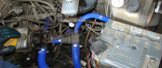
Replacing the fuel system of a VAZ 2110
We will talk about the transition from carburetor injection to injection. We will describe this process very briefly.
First of all, the carburetor lines are replaced with injection lines, as well as the gas tank is replaced. Next, the ignition coil, distributor and fuel pump are dismantled. The carburetor is dismantled along with the intake manifold, and in its place the injection manifold is installed along with a ramp and injectors. The next stage involves replacing the generator with a more powerful one, installing an electronic control unit and connecting all wires and sensors.
But everything is not so simple - in addition to all of the above, you will have to replace many more related parts (throttle cable, ignition module, sensors, air filter, etc.). For a deeper understanding of the replacement process, use a variety of photos and videos of repairs that can always be found on the Internet.
The principle of operation of an injection engine
So, after we have figured out the main components of an injection engine, let's see how it works. After the starter cranks the crankshaft, the DPKV tells the control unit which cylinder is in which position. In turn, the phase sensor reported the clock cycles. The control unit took this information into account and opened the injector in the cylinder in which the intake stroke begins. But he opened it for a reason, but for a strictly defined period of time, which, according to the tables, corresponds to the readings of the mass air flow sensor or DBP. This is how the working mixture was formed.
Video: how a gasoline injection internal combustion engine works
After the intake stroke has ended here, compression begins, at which time intake occurs in the other cylinder. Here the piston reaches top dead center, as indicated by the DPKV and DF, respectively, it is time to apply voltage to the ignition module, to the desired cylinder. To do this, the control unit contains two transistors, which take over two cylinders each.
Then, when the explosion occurs, the ECU looks at the readings of the knock sensor and adjusts the ignition timing for the next cylinder along the stroke. But that is not all. After this, when the gases reach the oxygen sensor, the control unit adjusts the composition of the mixture, namely, the opening time of the injector, which allows for the most efficient use of fuel and its combustion. If the ECU detects a lack of oxygen, but the throttle valve remains open, the idle air control valve opens slightly.
Engine warm-up and engine temperature sensor
This point is worth considering separately; let’s just say this is a small clarification. So, the engine warm-up mode is in no way connected with the readings of some sensors, that is, nothing depends on them. In particular, these are mass air flow sensor and air pressure sensor, as well as a knock sensor. The block, as already mentioned, contains certain tables, there are a lot of them, millions. So, during the warm-up mode, the ECU works strictly according to these tables and nothing else. This means that if the air to fuel ratio is written into it as 14.1:1, then it will be so. This figure is the generally accepted standard for operating temperature. So, until the engine temperature reaches the one specified in the firmware of the control unit, the warm-up mode will not turn off. Afterwards the ECU starts working based on the sensors.
Recommendations
Every car enthusiast can do a lot to extend the life cycle of all elements of the unit in question. To ensure that your car's power system works flawlessly, use the following recommendations:
- Refuel only at approved gas stations.
- Replace fuel and air filters in a timely manner.
- Use cleaning additives with caution.
- Try not to drive on a half-empty gas tank, especially in winter.
Source